

Video Tests
My loftiest of stretch goals for BMOW is to build a primitive video circuit, and connect the machine to a standard VGA monitor. To that end, I did some prototyping experiments on a breadboard recently to experiment with video generation. This was a completely stand-alone test circuit, not integrated into BMOW’s hardware in any way, but the results look quite promising! I still think it will be a lengthy, challenging project, but BMOW video output now looks likely.
I started with a standard 15-pin VGA connector from Radio Shack, and soldered the necessary wires to it. I then dug through all the technical docs on the VGA signal format I could find. The first hurdle was to build a circuit to generate the hsync and vsync signals at the required frequencies, and with the correct on and off durations for each cycle. I built two counters, using three GALs: a 7-bit horizontal pixel counter, and a 10-bit vertical line counter. The horizontal counter had a range of 127 pixels, with a 4MHz clock (250ns period), for a total duration of 127 * 250ns = 31.75us per line. That’s very close to the VGA spec of 31.77us per line for 640×480@60Hz. The vertical line counter used the horizontal counter’s rollover as its clock, and had a range of 525 lines. Again, that’s the VGA spec for 640×480. The extra lines between 480 and 525 are part of the overscan and vertical retrace, and aren’t displayed.
The sync signals were generated by the GAL counters. Hsync was defined as active during a portion of the 127 horizontal range, and vsync during a portion of the 525 vertical range. Lastly, I defined an “image” signal that was 1 whenever the horizontal counter was 64, and 0 otherwise. Connected to one of the VGA color inputs, that should have created a vertical line down the middle of the screen at pixel 64. Here’s a photo of my test circuit, including a ROM (stolen from BMOW) that I added during a later test:
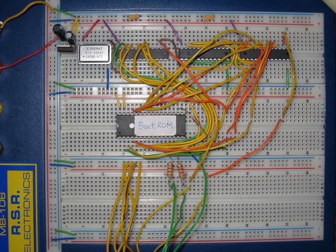
Unfortunately when I connected this Frankenstein up to a monitor, it did… nothing. It acted as if nothing were connected at all. I tried a second monitor and got the same results. Then I spent a long time rereading all the VGA signal documents again, and scratching my head, but I couldn’t figure out what was wrong. I even connected the circuit up to the oscilloscope, and verified that the hysnc and vsync signals looked as I expected. But no video = no progress.
One thing I’d been wondering about was the relationship of hsync to vsync. The spec defined the requirements for both, but I never found anything that talked about one relative to the other. Should hysnc and vsync both become active simultaneously, at the end of a frame? Or should they be ought of phase? On a hunch, I tried altering the circuit slightly so that hsync would be asserted in the middle of vsync, rather than simultaneously with its beginning or end, and… Eureka!
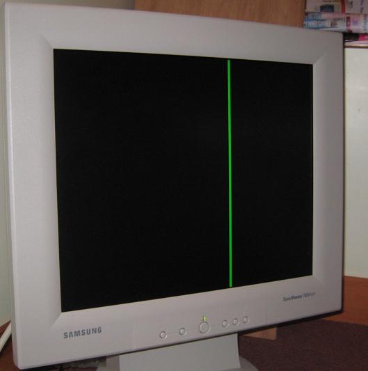
Holy crap, video! My circuit was generating honest to God VGA video, at the completely oddball resolution of 127×480. What’s not visible in the photo is the tremendous amount of noise in the image outside that green line, so there were some signal quality issues to contend with, but it was clearly working.
From there I began to experiment. Since I already had a 7-bit horizontal counter, why not try connecting the R, G, and B color inputs to the bits of the counter?
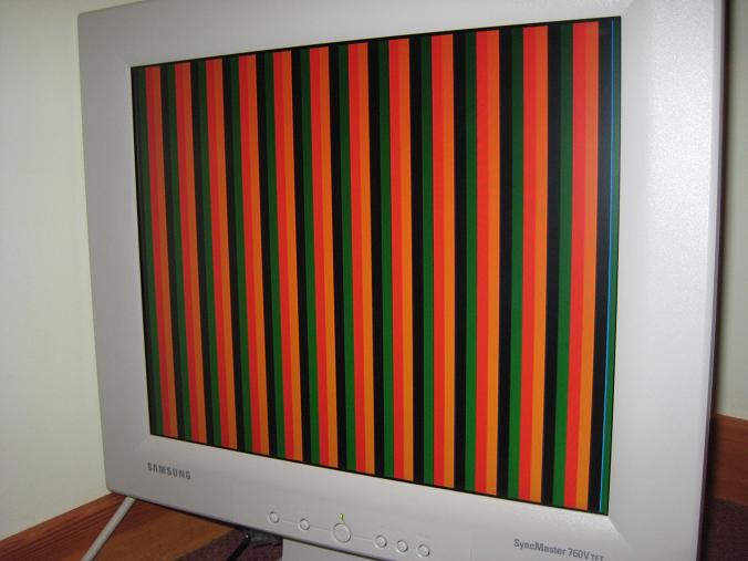
Or connect some of them to bits of the horizontal counter, and others to bits of the vertical counter?
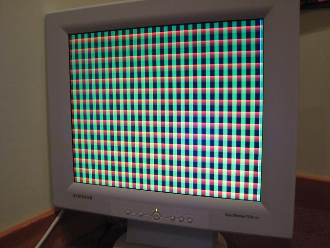
So far, so good. But to do anything useful, I needed to generate an image from data stored in memory, not just use bits from a counter. Luckily that proved to be pretty easy: I just used the 7-bit horizontal counter and 10-bit vertical counter to form a 17-bit address to a ROM, and then used bits from the ROM’s output data for the RGB channels. By sheer coincidence, the BMOW ROMs are 17-bit (128K), so it worked out perfectly. Here’s what it looked like, using one of the BMOW ROMs as the image source:
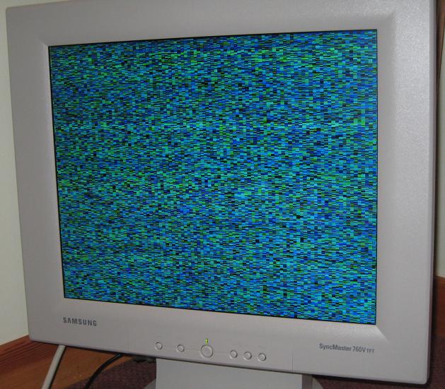
Mmm, noise! But memory-mapped noise, which meant I was getting close to something good. Now all I needed was a way to generate a 127×525 image as a contiguous, uncompressed file, so I could program it into the ROM for display. The 256-color BMP format proved to be ideal, as it’s uncompressed, and has a 1087 byte header that can be stripped out using a hex editor, leaving behind only the image pixels themselves, one byte per pixel. So I fired up the Windows Paint program, drew some awesome art using the pencil tool, saved it as BMP and stripped the header, and…
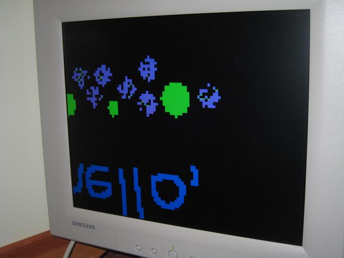
Argh, what the heck?! Are BMPs stored backwards? So close, just one more try…
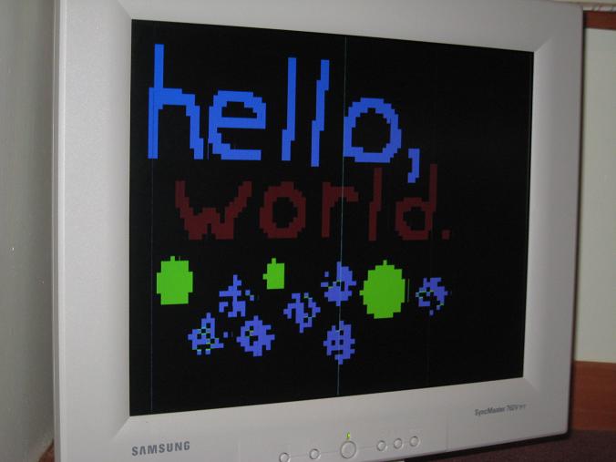
Ta-da! Memory-mapped video generation, using a 5-component test circuit.
All this looks promising, but there’s still lots more I’d need to do to get a useful integration with BMOW:
- There’s a LOT of noise in the image. In the last photo you can see a few stray vertical lines, in reality the image looks much worse. Grounding problems? Signal cross-talk?
- The horizontal resolution of 127 is too low to be useful. To get even 40 columns of text, with each letter 6 pixels wide, I need a horizontal resolution of 240. But higher resolutions require faster memory and other components, to get the pixel data quickly enough.
- Speaking of text, I probably need a text mode, with a character ROM that generates font glyph pixel data indirectly from a single ASCII character byte, in addition to the direct mode used in this test. That would require much less work from the CPU when displaying text on the screen.
- Horizontal and vertical blank signals are probably needed, in addition to hsync and vsync. These would be used to supress all data on the RGB channels during the portion of each line and frame that shouldn’t be visible. Failure to do this seems to confuse the monitor.
- The memory-mapped video image needs to be stored in RAM, not ROM, so it can be updated dynamically by the CPU.
- Some way to arbitrate access to the video RAM between the CPU and the display circuit is needed.
- A D-to-A converter is needed in order to get more than 1 bit per channel for red, green, and blue (8 colors total).
- The finished system, including components for all the functions not part of my test circuit, has to squeeze into the space remaining on the BMOW system board. That’s space for maybe 15 components, depending on their size. Ideally, it would still leave some space for audio circuitry.
It’s a tall order, but I’m pretty confident I can do it. I’ll post more updates whenever I have interesting news to report. Meanwhile, any suggestions on how best to approach the remaining design work are very welcome!
Read 19 comments and join the conversation19 Comments so far
Leave a reply. For customer support issues, please use the Customer Support link instead of writing comments.
Awesome! I assume this wasn’t TOO difficult, but of course, it’s never easy. Nice job! That’s something I’m interested in using on my project… once I get it off of the ground. I’m working on the adder. I should just buy a few XOR chips instead of building them from NAND’s… ;D
Oh and yeah, I remember, BMP’s are stored backwards. I forgot why, but it said that in the old windows game programming for dummies first edition.
Good stuff! You’ve got me thinking about using an EPROM to generate proper composite sync signals for video. 625 line, 50Hz here, of course, and PAL for colour (although I’d stick with RGB and not composite). I want to do something like this for a 6809-based machine, or possibly with an AVR microcontroller. Or even both.
Thanks! It should be fairly simple to adapt this to generate PAL video if you want to connect to a television set, but you may find it easier to use a VGA monitor like I did. I can post the schematics for my circuit if you’d like.
For PAL, you would just modify the vertical counter in the circuit to count to 625 rather than 525. The horizontal period of 31.75us would be the same. That would give you a frame time of 625 * 31.75us = 1.98 ms, which is 50.4 Hz. Should be close enough.
I can’t recall if PAL uses a composite sync signal rather than separate hsync and vsync, but if it does, you can just XOR the two together to create a composite sync.
One reason for the noise is that I suspect you are using the ROM outputs as RGB data directly. Each time you change the address, the ROM data will be invalid for some time before it settles to the new data. You can solve this simply by using a register on the RGB data. This register should be be clocked each pixel when you know the ROM data is valid, so there is no period of unspecified data (at least that the monitor sees). Of course, this will delay the video data by one pixel, but that shouldn’t be a problem.
Another reason may be that the RGB inputs are in fact analogue at 75 Ohm impedance. Driving them with digital outputs directly (if that is what you are doing) will saturate the inputs and also make subtle variations in the logic levels very apparent on the monitor. Buffering the outputs and using a potential divider on each output should greatly improve this. Some quick back-of-the-envelope calculations indicate that a 560 Ohm series resistor and an 82 Ohm resistor to 0V (in parallel with the monitor) should give you what you need with an impedance of about 75 Ohms. The drivers need to be capable of sourcing 9mA without “sagging” significantly, so that shouldn’t be to difficult to find.
I did something broadly similar to this many years ago, but I used a sea of 74-series logic – not even LS or HC! It was an even bigger mess of wires, but it did work.
Great feedback, thanks! You’re right about the way I was using unregistered ROM outputs as the RGB data. I reached the same conclusion yesterday, and added a register as you suggested, and it helped a lot. The bright vertical lines that you can see in the photo are now gone, although there are still some subtle gray vertical lines.
The G and B values are connected from the register through 330 Ohm resistors to the VGA connector. There is no direct connection to ground, other than through the VGA connection to the monitor. The R value is connected through a 1K resistor, because I only had two 330 Ohm ones to test with. I’ll get some more resistors and try creating a voltage divider as you described.
When you suggested buffering the outputs, what do you mean exactly? Connect the register’s outputs to a transistor configured as a voltage follower, or a ‘244 bus driver, or something along those lines? Would it be unwise to put the voltage divider directly at the output of the register?
If you are happy that your register can source about 9mA with an output high voltage of about 5V, then you will be fine. That’s doubtful, however. CMOS is good here as it is pretty much “rail-to-rail” but you’ll need to find a device with a high-current output, such as a 74HC125 or 74HC244.
Any supply noise on the buffer will be coupled to the video, so you may well get better results if you build this with better supply and ground wiring (hard on plug-in prototyping board)! You may find it worthwhile running the buffer supply (only) through a small choke (even a few microhenries will help) and being very careful with the decoupling. That implements an L/C filter, thereby ensuring that noise generated by the rest of your logic doesn’t find its way onto the video. This is more likely to be an issue when you integrate the video hardware with the BMOW processor.
Good luck, and I’m keen to hear about the results!
Merlin
Yesterday, I went to Tech Adventure in Bristol (I was showing some of my collection of retrocomputers) and picked up a VGA card from the swap-shop table. It has a socketed UMC 70C171 colour palette chip. This might be a handy chip to play around with for video generation, and it makes it very easy to produce analog RGB signals.
Wow, that UMC 70C171 looks fantastic! I had no idea that such parts existed! Unfortunately it’s long-since obsolete, and I couldn’t find any online suppliers for it, and nothing on eBay. Anyone have any good ideas where I might be able to find one, maybe from a used/obsolete parts supplier? According to Octopart, similar parts are IMS G171, Hitachi HD153129, and National DAC0630. I couldn’t find suppliers for any of them, though. John, what model of VGA card did you buy that contained that socketed chip? Maybe I can find one.
My video system design is beginning to coalesce, and hopefully I’ll have a design to post for feedback soon. It’s going to be about 20 components, which will be very close to what I can fit in the remaining space on the board. Once the design is finished, I’ll determine the layout and see if it fits. If not, I can eliminate some parts by scaling back on the features. That color palette chip would save me 4 or 5 components, and improve the overall functionality somewhat too.
My tentative design has a base resolution of 320×240 with 2 colors (1 bit per pixel). Horizontal resolution can be halved to get more bits per pixel, so there’s also 160×240 @ 2bpp and 80×240 @ 4bpp. Vertical resolution can also be optionally halved or quartered too, to keep the pixels square.
There’s also a text mode, in which each VRAM byte is used as a lookup into a character generator ROM, rather than used directly.
Colors values are indexes into a 16 entry palette. Each palette entry is 8 bits: 3 bits red, 3 bits green, 2 bits blue.
The coolest feature (if I can make it work) is that the horizontal and vertical resolutions and text/graphics mode switch are controlled in the VRAM data itself, and so they can change every scanline. The first byte of VRAM for each line defines the settings for that line. So it should be possible to create a screen where the top half is 320×120 hi-res 1 bpp, the next quarter is 160×60 2 bpp, and the bottom quarter is 40×7 text. Additionally, each line can select a different palette to use, from a “palette of palettes”.
If this thing doesn’t collapse under the weight of its complexity, it should allow for some pretty cool effects. As it is, it’s nearly half the size of all the rest of the BMOW hardware combined!
I used to work for INMOS, the company that originally invented the palette chip and designed the G171. The design was based on a part of the in-house 68000-based CAD system that the company used to build chips. The G171 was used in all the early IBM VGA boards. A long time ago, there was an INMOS data book with lots of information about the parts.
So, you can see why I grabbed that old VGA card when I saw it!
BTW, the VGA card was a free give-away! It’s ISA, not PCI, it has a row of four crystals on the far left-hand end, it has a BIOS EPROM with Cirrus Logic and Award names on it, the date codes are all in1991, and — aha! — it has a number: VP44B. That’s all I can tell you about it, I’m afraid.
Wow!
Amazing!
I am simply whelmed.
That idea behind video generation is definitely far ahead of the ideas that I suggested via those books for video creation.
After all the VGA specifications evolved well after the first real color graphics using the methods that Apple used for example.
And John Honniball, I remember Inmos. They had some great ideas. I agree that the video card you found was a splendid idea.
Thanks to your great post, I’d encouraged.
so I tried to do vga on breadboard. 🙂
and as your advice, I bought 100mhz kenwood readout oscilloscope. Thank you. If I didn’t buy oscilloscope, I never made vga sync timing.
I used 20MHz osc, 6 4bit-counter(74LS139P), 2 GAL20v8.
Here is my results.
vga 15pin female wirewrap connector:
http://cfs10.tistory.com/image/27/tistory/2008/12/02/01/53/49341692a43e6
breadboard vga logic:
http://cfs10.tistory.com/image/24/tistory/2008/12/02/01/53/493416920ca28
vga on lcd (524×480):
http://cfs10.tistory.com/image/1/tistory/2008/12/02/01/53/4934169157aab
http://cfs15.tistory.com/image/8/tistory/2008/12/02/23/48/49354ad871920
Thank you. but now i got a problem with finding palette dac chip.
I found ramdac list on web. but it’s hard to buy a 6-bit ramdac of them.
http://www-user.tu-chemnitz.de/~kzs/tools/whatvga/ramdac.txt
Awesome job bro! I’m excited that you got the VGA generation working!
Unfortunately it will probably be difficult to find a suitable palette chip. I was lucky that I found some very old PC video cards with palette chips that I could remove and use for BMOW.
Of course you don’t really *need* a palette chip, if you want to do something simple. You can get eight colors by connecting three bits of your video memory directly to the R, G, and B inputs of the VGA. Or you can make a 256-entry direct color system by encoding all eight bits as RRRGGGBB and building three R2R resistor ladders to serve as DACs. That’s what I had originally planned to do.
When I tried to find old pc for old video card, only what pc i can get is pentium-2 upper. haha. so I give up for 6bit ramdac now.
I will try to do RRRGGBB encoding as your advice after 8-color eeprom image show, too :D. now I’m buying some eeprom…
Thank you!
How about a Motorola MC6845 from an old video card?
(I mean /really/ old: MDA, CGA, EGA, Hercules or clones thereof)
It handles both timing, sync pulses, and address generation.
Hi, I know that your post is old but I am trying to build a VGA controller for a PIC project and I just yesterday I found your website. I know nothing about FPGA so I am thinking of using the PIC itself and some 10-bit binary counters. The pic is supposed just to paint the gfx in a memory chip (probably an sram) and the counters should somehow read the RGB info from it and perform all the necessary syncronization with the monitor. My logic still has many gaps.Can you help me out? Do you have any shematics for your circuit above?
There are lots more posts in this series about development of the video system – just keep reading! A block diagram for the final design is at http://www.bigmessowires.com/video.pdf and the schematics are http://www.bigmessowires.com/schematics.pdf.
I’d recommend starting as I did here, and building a circuit that generates a fixed VGA image, with a random-looking color pattern provided by some logic gates or a ROM. That will prove that you can generate a working VGA signal that your monitor likes. Then work on adding SRAM to the circuit to provide the colors, and having the contents of SRAM updated by the PIC. You’ll need to work out some arbitration system to prevent the PIC and the display circuitry from attempting to use the SRAM at the same time.
Thanks for your reply. I ‘ll try to follow your route. I’ve already understood the problems on using plain binary counters since I have to use additional logic to check for HSync and VSync stage e.g. is Hsync cycle less than 95? etc…
I don’t have any gals on hand and I have never used them so I probably have to buy a dozen of AND gates but this does not sound as a good solution. Any ideas about how to avoid it?
Regarding the SRAM, the easy way out would be to use two of them. So write to the first one while reading the second one and vise versa.