

Soldering Self-Confidence
I don’t like to solder. Nor am I very good at it, despite having soldered loads of boards. The temperamental solder never seems to flow where I want it. Surface-mount soldering in particular used to scare me enough that I didn’t even attempt it. A few years back, I gave Wired my opinion that surface mount chips are out of reach for non-professionals, or at least for anyone without advanced skills and special equipment.
Since then I’ve changed my outlook, and I now believe that successful soldering is primarily a matter of self-confidence. The only soldering project you’re 100% guaranteed not to complete is the one you don’t attempt. Sure, you might mess things up horribly, but you probably won’t. And even if you do make a mess so awful that it can’t be salvaged, what’s the worst that can happen? You’ll lose a few dollars worth of parts, but gain valuable practical experience. Consider it the cost of your soldering education.
I arrived at this conclusion after some reflection about my own soldering track record. I promise you, I am not a very skilled solder technician, and yet in all of the many boards I’ve assembled with countless hours of sweat, tears, and swearing:
- I have never destroyed a part
- I have never failed to get the board working
Some day I’ll screw up and ruin a part or a board, but the fact remains that the biggest thing holding me back from more complex soldering projects was not any particular skill or tool, but just the confidence to attempt the project in the first place.
BMOW Soldering Q&A
There are tons of great tutorials on the web about the mechanics of soldering, like how to bring the iron and the solder to the joint, and how to drag-solder SMD parts, so I won’t discuss that. Instead, I’d like to share some ideas about my overall approach to soldering, in the hopes that it may help others.
Soldering: Now With Undo!
Q: How can I prevent making mistakes when I’m soldering?
You can’t. I used to believe that soldering had to be done perfectly on the first attempt, and mistakes were fatal. Maybe I was vaguely aware of some techniques to fix mistakes, but assumed they were “advanced” techniques that didn’t apply to me. Nothing could be further from the truth! You wouldn’t expect to type a long document on a keyboard without a backspace key, and making and fixing dozens of typos is a normal part of the process. Soldering is just the same. Even on a small board, I normally make five or so soldering mistakes like bridges or misaligned parts, but I’m able to fix them quickly and move on.
Q: So how can I fix mistakes?
Solder wick (desoldering braid) is your friend. Got solder where it shouldn’t be, or too much solder on a joint? Lay the braid on top of the solder you want to remove, then press down on the braid with your iron. The excess solder will be sucked right into the braid. If you’re not soldering with solder wick, then your keyboard doesn’t have a backspace key. Get some.
Flux is even more useful than solder wick. Your solder may have some flux in the core already, but trust me, you need more. I use a flux pen that works just like a magic marker, enabling me to paint flux easily on to any joint or pad. Got a solder bridge between two chip pins? Apply some flux, then touch the pins briefly with the iron, and the bridge will often disappear. Got clumpy solder that doesn’t seem to want to flow where it should? Add more flux and reheat. Still not working? Add more flux. Then add still more. Flux fixes practically anything.
Q: I want a nice, professional-looking board. Won’t all that fixing look messy?
Yes, your board will probably look like crap, but it’s not a beauty contest. Let go of the idea that the board should look pretty. The only important question is whether it works.
Q: What if I make a mistake that I can’t fix?
Whenever I’m assembling a board, I always buy enough parts to build two of them. That way I’m less nervous about screwing up the board, because I can always trash it and try again with the second board if I make a huge mistake.
Before you trash a failed board, though, give it some extra effort in the attempt to fix it, and don’t be shy about it. Solder on some jumper wires. Burn things. Use a hammer. If you break it, you’re no worse off, but you’ll have gained more experience. Then try again with board number two.
Small Doesn’t Mean Difficult
Q: Some of those SMD parts are awfully small– those can’t really be hand-soldered with an iron, can they?
Yes, they can, easily. The surface tension of molten solder naturally makes it flow where it should, and soldermask deters it from flowing where it shouldn’t, even for very small parts. Mistakes are easy to fix with soldering wick or flux.
Q: OK, but what about those really tiny parts, with like 0.5 mm pin spacing?
Yes, those too. Easily.
Q: What about those plastic ribbon connectors on LCD screens, with the tiny metal contacts?
Those are even easier.
Q: But what about QFN parts that don’t even have exposed pins?
You can hand-solder those too, using an iron, by tinning all the pads on the board first. A hot-air tool makes it easier.
It’s Not About The Tools
Q: What do I need in order to do surface-mount soldering?
Not much beyond what you already have, probably. A regular iron with a regular tip is fine. I use the chisel tip that came with my iron, which is several times larger than the pins on the chips I’m soldering. It’s fine if the tip is larger than the pins, because you’re not going to do pin-by-pin soldering of SMD chips. In fact, for all but the largest SMD packages, the iron tip will always be larger than the pins.
Other essential ingredients:
- Flux. Use a flux pen, flux in a jar, or whatever other form works best for you. Flux everything liberally before soldering. Rule #1: If you’re having difficulty soldering a part, you need to add more flux. If that fails, refer to rule #1.
- Magnifier. Most SMD joints will be too small to see clearly with the naked eye. To inspect finished joints for tiny solder bridges or other defects, you’ll need something to magnify them at least 3x and preferably 10x. I use a cheap 10x loupe, which is like a monocle with a magnifying lens. USB microscopes also work well if you want something fancier.
- Tweezers. You need something to maneuver those little parts into place, and hold them there while you solder them. You’re hands aren’t going to cut it.
- Drug-Free Bloodstream. Your experience may be different, but I can’t do fine pitch SMD work within a few hours of drinking coffee. Even tiny amounts of hand twitching make it nearly impossible to align parts with sub-millimeter accuracy.
Circuit Debugging Is Fun
Q: How can I make troubleshooting easier when assembling a board?
Don’t assemble the entire board in one pass. I always assemble boards one functional section at a time, and test that section as much as possible before beginning the next one. This greatly reduces the number of possible causes that must be investigated if a problem is discovered.
The first section on nearly every board is the power section. Solder in the battery or power jack, voltage regulator, and other related parts. Next, measure the resistance between power and ground. Don’t just perform a continuity check, but actually measure the resistance. For most small electronics projects, it should be unmeasurable, or else in the megaohm range. If it’s below about 10K ohms, then you may have a very small solder bridge somewhere. If it’s zero ohms, then you have a dead short between power and ground, or a chip that’s soldered in backwards or something.
If the resistance checks OK, then turn on the power and measure the voltage on all the VCC pins. If it’s not what you expected then stop, and don’t proceed with further assembly until you’ve first fixed the power problem.
For microcontroller projects, I normally add the microcontroller next, as well as the programming header and any other components required to get the MCU running. Connecting with the external programmer and reading the device ID or fuses is a good way to verify that the MCU is working properly.
The remaining functional sections vary greatly depending on the project, but often there’s an LCD or other info display that can be tested first, and then buttons or other input hardware. After each section, recheck the resistance between power and ground before turning the device on, since each new part added brings a risk of an accidental short-circuit.
Q: I assembled the board, and the soldering all looks good, but it doesn’t work. What can I do?
In my experience, failures are almost always caused by short circuits (usually due to solder bridges) or open circuits (cold solder joints, or too little solder).
Short circuits are easier to diagnose, since they can usually be seen under magnification if you look in the right spot. Use your multimeter in continuity check mode, and test for continuity between every signal you suspect has a problem and its neighbors. If you’re fairly certain there’s a short, but can’t find it, then test again by measuring the actual signal-to-signal resistance instead of continuity check mode. For some types of signals, even a very small solder bridge with a resistance of 10K+ ohms can be enough to break the circuit, and those typically won’t produce a beep when in continuity check mode.
If that fails, visually reinspect every chip pin for possible hairline solder bridges to its neighbors, as well as bridges between pins and vias. If you see anything that looks like it could possibly be a short, then apply some flux and reheat the joint to clean it up.
Open circuits are a bit trickier, since they can’t be conclusively diagnosed just by looking at them. If the solder in a joint looks cloudy, or there’s very little solder, then check the continuity with your multimeter to make sure everything’s connected as it should be. When checking continuity to a chip pin, it’s important to touch the probe to the actual pin, and not to the pad underneath the pin, since the pin-to-pad joint itself is often a point of failure.
As with testing for shorts, it may be useful to test open circuits by measuring the actual resistance instead of merely performing a continuity check. If two points that should be connected measure 1K ohm of resistance between them, it may be enough to elicit a continuity check beep, but something is clearly wrong.
If all the continuity checking and resistance measuring fails to identify the problem, then you’ll need to perform live circuit debugging. Turn on the power, and start measuring voltages at various places in the circuit, verifying that the voltages are as expected. For DC voltages, this is easily done with a multimeter. For something like a clock signal with a 50% duty cycle, you can still use a multimeter, and expect the measured voltage to be 50% of the high-t0-low voltage swing of the clock.
For other time-varying signals and data signals, you will probably need to use an oscilloscope to observe what’s happening. A few common symptoms and their causes are:
- stuck at VCC or ground: short-circuit to power, ground, or another DC signal, or an unconnected signal.
- stuck at some middle voltage: contention (two different sources attempting to drive the signal), or an unconnected signal (open circuit).
- sort-of correct-looking signal, but reduced in amplitude and shifted far towards VCC or ground: hairline short-circuit to power, ground, or another DC signal.
- random wavy noise pattern: unconnected signal (open circuit).
If all else fails, then you may need to cut traces or remove parts from the board in order to isolate the problem. Remember, if it’s already broken then you’re unlikely to make matters worse, so don’t be shy about getting in there and banging away to debug the board.
Read 7 comments and join the conversation
7 Comments so far
Leave a reply. For customer support issues, please use the Customer Support link instead of writing comments.
I teach surface mount soldering classes to people I know and the most common response I have received is “That wasn’t as hard as I expected.” I know I felt the same way 18 and 10 months ago. (I screwed up bad and gave it up for a while) Now though, I look at a 0.4mm pitch DFN part or an 0201 passive and it ceases to worry me.
Of everybody I have taught, only one person could not solder an 0603 part. (A old guy who gave up with the part angled about 15 degrees off.)
I’ve not yet tried anything smaller than 0805 passives, but those are pretty easy. Getting them out of the packaging without losing them in the carpet is the most difficult part. You’re hand-soldering 0201’s?
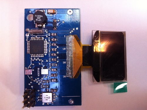
Totally random aside: do you see the photo above with the LCD on the left or right? Viewing this post in Mac Chrome it appears on the right, but viewed on my phone it’s on the left. Some kind of embedded orientation metadata in the image file?
Parts on the floor are usually not even worth it to get 0201 or otherwise. I only do if its expensive or my last one :).
Everybody I have heard about has their own way of dealing with the packaging, so grain of salt and all that, but I use flush cutters to cut just the parts I am using now out of the tape. I then use the point of my tweezers to remove the plastic strip off the top. Then its just tipping the parts out onto the desk, flipping them right side up (here comes the step I lose passives) and placing them with tweezers.
Besides, the only real considerations with 0201 versus 0603 or similar are: Are the points of your tweezers bigger than your part?, no caffeine, and part visibility. Resistors and ceramics are easy, I should probably pick up a magnifier before trying to solder 0201 diodes.
Also do you use sparkfuns 0805 footprints or a footprint designed by somebody who solders 0805 on a regular basis. SFE’s 0805s are too small and are a relative pain to hand solder.
Lastly, 0402 is a bad size to step to after doing a total of 5 0603 parts for the first time.
Linux Chrome Beta: LCD is on the right, not that it helps much.
Also http://random.alex.ferrouscanine.com/IMG_1883.JPG .
You can see my placement is not perfect. They do work and the ones that had a bast of hot air look much better, but I cannot find the test board they were mounted on.
I have a few thoughts, having helped out at a Bristol Hackspace SMD soldering workshop. Photos are in the middle of this set: http://www.flickr.com/photos/anachrocomputer/sets/72157627839332744/ and I made a blog post about it, here: http://anachrocomputer.posterous.com/surface-mount-soldering-workshop
Firstly, we used stereo microscopes with a magnification of 20x. My own microscope will also do 40x, but that’s too much. We used good lighting, which is vital when working with tiny parts. For inspection, we also had hand-held loupes and head-worn magnifiers. The magnifiers, like the microscopes, give a “3D” image, which is much more useful than a flat image from a single lens.
As for spotting unsoldered pads, I find that I can line up the PCB to catch a reflection on the flat, tinned pads. If that flat, reflective surface still exists after soldering, it’s not soldered! A good solder ‘blob’ will be convex, and reflect light quite differently from a flat pad.
FireFox 3.6.x + WinXP -> LCD is on the right side of photo.