

Homemade CPU First Boot
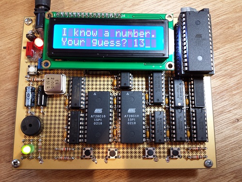
YES, IT WORKS! The Nibbler homemade CPU is up and running, and it can play “guess the number” like nobody’s business. Awesome! If you haven’t seen my earlier posts, Nibbler is a 4 bit CPU built from standard 7400 series logic chips – individual counters, registers, buffers, and gates. It’s an educational example of a simple CPU that’s easy to understand and build, but still capable of running games and other interesting programs. The CPU contains 17 chips in total.
With all the advance design work and simulation that went into Nibbler, I was fairly confident it would work, but it’s sure nice to see it confirmed in real hardware. Construction was slow and tedious, but went fairly smoothly. After soldering the buttons and passive components, the chips were mounted in sockets and connected by wire-wrap. The whole construction process took about five days.
Some specs:
- 4 bit custom-made CPU
- 12 bit addressing, 4K address space size
- Harvard architecture – separate program and data memory spaces
- 2 MHz clock speed, 2 clocks per instruction = 1 million instructions/sec
- Thirteen 7400-series chips in the CPU data and control paths
- Two 28C16 EEPROMs store microcode for generating internal control signals
- 4K x 4 SRAM (CY7C168A)
- 28C64 EEPROM stores programs
- Four pushbutton inputs
- 16 x 2 character LCD
- Audio speaker
- About 100 mA current draw at 5V
For lots more detail on how Nibbler works, see the project home page.
Fun with Debugging
During construction, I ran into a couple of errors in my schematic. I accidentally reversed the Zero and Carry inputs to the microcode ROMs. You’d think that would be an easy thing to catch – notice that all the instructions involving the Carry flag didn’t work, double-check the wiring, and aha! Unfortunately it didn’t happen that way at all.
At the time I ran into this problem, I was part-way through construction, and I hadn’t yet connected the Flags register’s Zero input to anything. It was just floating. Because of my schematic mistake, the CPU was actually using this undefined Zero flag when it thought it was using the Carry flag. The crazy thing was that it still worked sometimes! After powering on the CPU, the Carry flag appeared to work normally and programs ran fine for about two seconds, after which the whole thing went to hell. Because it worked briefly, I assumed there was some kind of overheating problem, or maybe a timing problem caused by changing propagation delays as the chips warmed up. I spent almost a whole day trying to track down the problem. At least it gave me an excuse to use my logic analyzer!
Debugging the Carry flag with the logic analyzer
How is it possible that the CPU worked for a few seconds, when it was using the completely wrong flag? It turns out that because Zero wasn’t yet connected to anything, and the Zero and Carry wires ran side-by-side, capacitive coupling caused the floating Zero input to follow the value of the Carry flag, at least for a little while. What?! Yup, the combination of reversed wires and an unconnected input caused the right value to jump to the wrong wire. After a few seconds, some stray capacitance somewhere charged up to the point where this little trick no longer worked, and the CPU conked out. As soon as I swapped the wires and connected the Zero input properly, the CPU began working nicely.
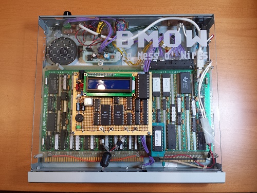
Son of BMOW 1
It’s interesting to compare Nibbler with BMOW 1, my first homemade CPU. Compared with BMOW 1, Nibbler is tiny! The whole thing fits in the palm of my hand. BMOW 1 looks like a giant in comparison. And Nibbler has just 17 chips, all of which are either memory or 7400 series logic. BMOW 1 has 65 chips, many of which are GALs (programmable logic). The size discrepancy would be even greater if BMOW 1 were constrained to use only 7400 series logic.
How can Nibbler be that much smaller? The major difference is that BMOW 1 supports lots of I/O devices that Nibbler doesn’t, like a PS/2 keyboard, VGA video, a serial port, 3-voice audio, and a real-time clock. All those device support chips really add up. BMOW 1 also has wider data and address paths, and has a hardware stack register and some other CPU features that Nibbler lacks. BMOW 1 is a very cool machine, but it carries a lot of bloat, making it difficult for people to understand how it all works. Nibbler is more like a minimal CPU example, with just enough power for a few basic games and demos.
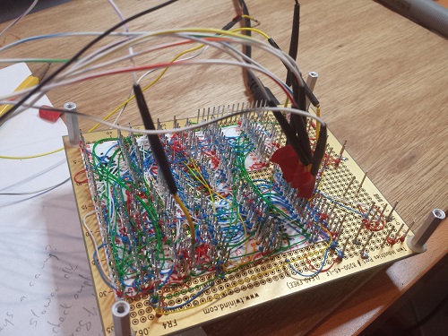
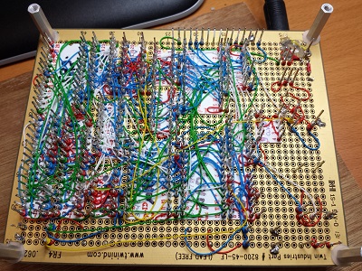
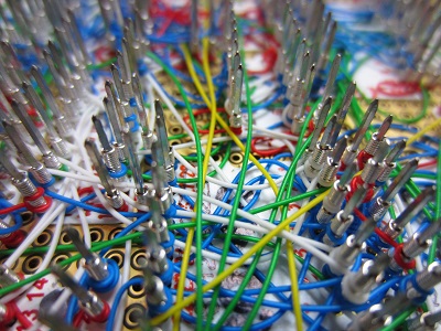
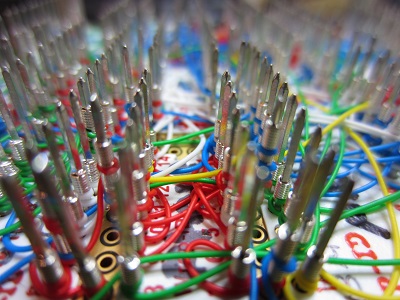
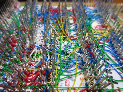
Wires!
Because this is the “Big Mess o’ Wires” blog, I’ll conclude with some gratuitous wiring photos. Enjoy!
Read 12 comments and join the conversation
12 Comments so far
Leave a reply. For customer support issues, please use the Customer Support link instead of writing comments.
Gratulation. Great work.
I’ve followed your progress on Nibbler with great interest, and it’s great to hear that it is working.
I’m interested in trying to clone it. But I’d probably try to build it on a breadboard rather than any kind of protoboard, at least on the first attempt. Is there anything that would make that a bad idea?
David, breadboards make not-so-great electrical connections, and are especially bad for high speed circuits, but at 2 MHz with the parts used here I think you’ll be OK. Just keep the wires as short as you can! 🙂
Besides keeping the wires short, you’ll want to make sure the power and ground connections allow the current to flow easily. There’s a small amount of resistance at each solderless contact and all of the conductors have self inductance. For individual signals the currents are small enough that this resistance and inductance aren’t too important at these slow clock rates, but the currents accumulate in the power and ground lines, potentially to the point where one of these goes briefly out of spec and something glitches.
For example, when a chip simultaneously switches several of its outputs from high to low, this puts a higher than average demand for current on the ground connection. Without a solid ground path, ground inside the chip can rise significantly relative to ground in the rest of the circuit, at least for a little while (and similarly the power dips when outputs switch from low to high). Since the inputs are judged relative to the chip’s idea of ground, this can make a logic high input temporarily look low or make a spurious clock edge appear. Bad things that are hard to troubleshoot.
So don’t be afraid of having redundant power/ground connections or joining the power/ground buses at multiple locations. For digital circuits, the problems from creating ground loops are outweighed by the problems of not having a low enough impedance path for power and ground.
And as usual, awesome work Steve!
I may have celebrated a little too soon, as it seems there’s an intermittent problem with writes to RAM. It works OK in the guess-the-number program, but when I started working on an audio tone generator that uses RAM locations to control frequency and duration, I got noise instead of pure tones. Looking carefully with the logic analyzer, I found an instance where I wrote $F but read back $7. I suppose it could be the read that was faulty instead of the write, but I doubt it. I suspect a timing problem, where the RAM address or data inputs are changing before the chip select is de-asserted. Ugh. If I leave the CPU turned on for about 10 minutes, the problem mostly goes away. I guess it likes to be warm. 🙂
Very nice! It’s a shame it doesn’t support indirection – with pointers and a stack you could make it into a genuinely useful machine in one fell swoop.
Von Neuman lets you do this with self-modifying code, but you’d have to either add more chips or halve the speed to make this a VN machine.
Awesome nevertheless!
[…] from the Big Mess o’ Wires blog has built a Home Made CPU called the Nibbler. Why the name? Because it is a 4 bit CPU (half of a byte is a nibble). Other than a creative name […]
It looks like a piece of art! Great work!
[…] from the Big Mess o’ Wires blog has built a Home Made CPU called the Nibbler. Why the name? Because it is a 4 bit CPU (half of a byte is a nibble). Other than a creative name […]
don’t get it
Would you consider sharing your schematic?