

68 Katy PCB Style
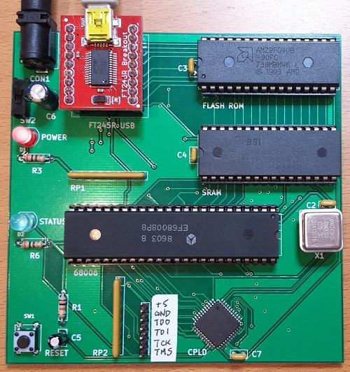
The 68 Katy PCB version is working! Mostly! I’ve had the parts and PCB on hand for a while, but only recently got around to assembling and testing the thing. Now instead of a breadboard that runs uClinux slowly, I’ve got a 10 x 10 cm PCB that runs uClinux slowly. Ah, the sweet taste of success.
Assembly
The assembly process went smoothly, even though I forgot to label some important items on the silkscreen like the JTAG pins. Revision 2 can fix that. The only real soldering challenge was the Xilinx CPLD, a 44-pin SMD chip. The PCB footprint for the CPLD wasn’t the best, as the pads were barely any larger than the pins themselves, making it somewhat difficult to solder with an iron. But thanks to my experience hand-soldering hundreds of similar chips with Floppy Emu, I was able to use a drag soldering technique to get the CPLD down with only minor rework required. The rest of the through-hole components were quick to solder, and I finished the board off with a fancy blue status LED.
Since I don’t own a Xilinx programmer, I used a Bus Pirate to program the CPLD. The process isn’t too bad for occasional or emergency use. Using the Xilinx IDE software, you can create a .xsvf programming file for your design and the target chip type. Then you flash a special XSVF player firmware onto the Bus Pirate, connect the BP’s pins to the JTAG header on your board, and finally run a Windows utility to program the .xsvf file to the chip. I was stuck for a while at the point of flashing the alternate firmware to the Bus Pirate, since I’d forgotten that you must manually invoke the bootloader before updating the BP’s firmware. Once I figured that out, the actual CPLD programming was quick.
Boot Up
I pulled the 68008 CPU, RAM, and ROM from the breadboard, stuffed them into the sockets on the new PCB, and confidently flipped the power switch. Oh my eyes, that blue LED was blinding! Who chose that thing?? I tried to take a photo of it, but it’s so overwhelming that it just looks like a white dot on a dim background. Next time I’ll stick with red, but for now I think I’ll need to wear sunglasses when using this thing. 🙂
Of course the board didn’t work. When powered on, it appeared to do nothing at all. I poked and prodded for a while with a logic probe, and all the signals seemed to be behaving normally. I don’t know why I always fall back to the logic probe, when I’ve got two logic analyzers and an oscilloscope that would give me much better information, but somehow those tools always feel like too much hassle to get out and set up.
After a few minutes I remembered that I’d made a small change to the address map for the PCB version, so the software for the breadboard version won’t be directly compatible. In order to save CPLD pins and board traces, I changed the way the RDF and TXE status bits are read from the FT245 USB FIFO. In the breadboard version, these status bits appear in different bit positions at a single memory address. But in the PCB version, they appear in bit 0 of two different memory addresses. Both my monitor program and my uClinux FT245 driver needed to be modified to reflect this change.
BREADBOARD 68 KATY               PCB 68 KATY
00000 - 77FFF : ROM              00000 - 77FFF : ROM
78000 - 79FFF : serial in        78000 - 79FFF : serial in
7A000 - 7BFFF : serial out       7A000 - 7BFFF : serial out
7C000 - 7DFFF : serial status    7C000 - 7CFFF : serial status RDF
                                 7D000 - 7DFFF : serial status TXE
7E000 - 7FFFF : LED register     7E000 - 7FFFF : LED register
80000 - FFFFF : RAM              80000 - FFFFF : RAM
Once I made that fix, the board was up and running! I played with the monitor program, booted uClinux, and played Adventure. Everything seemed solid.
“Mostly”
The breadboard version of 68 Katy ran at 2 MHz, and didn’t work at higher speeds. I initially tried the PCB version at 2 MHz as well, and everything was great. But when I tried faster speeds like 6 or 8 MHz, it didn’t work at all — it just did nothing, or spewed endless garbage characters. I was disappointed, because I’d hoped the cleaner signals on the PCB vs the breadboard would enable the computer to run at higher speeds.
But wait! After a lot of fiddling around, I discovered that the PCB version of 68 Katy had no trouble running at higher speeds, it just had trouble resetting at higher speeds. If I moved my hand around the CPU while repeatedly pressing the reset button, eventually it would work and the monitor prompt would appear. After that everything was fine, and I could use the monitor program without trouble, or boot into uClinux and play Adventure or run vi. I successfully tested the hardware at 2, 4, 6, and 8 MHz. As long as I could get it to reset cleanly, then it ran flawlessly.
So what’s going on? By touching different CPU pins with my finger, I think I’ve narrowed the problem down to either the /IPL2 interrupt pin, the /RESET and /HALT pins, or the reset button debounce circuit. /IPL2 is the 100 Hz timer interrupt, and it seems like maybe the CPU is immediately hitting an interrupt the instant it comes out of the reset state. Since the interrupt vectors haven’t been initialized yet, it crashes. That does’t fit what I know about the 68008, though – the datasheet says interrupts will be disabled after a CPU reset. Maybe there’s a bug in my monitor program that enables interrupts before the vectors are initialized, but I double-checked and didn’t see anything like that. Anyway, it’s the same monitor program that worked fine on the breadboard.
A more likely explanation is a problem with the reset signal itself. The board has a pushbutton with an RC debounce circuit, with the pushbutton signal connected to a CPLD input. The CPLD uses that to generate the /RESET and /HALT signals for the CPU, which are a little bit strange in the 68000 family. In order to reset the CPU, both /RESET and /HALT should be pulled low. But to exit the reset state, /RESET and /HALT should be allowed to float, and pulled high with an external pull-up resistor. That’s because those signals are actually bidirectional, and are sometimes pulled low by the CPU itself. On the 68 Katy PCB, both signals have independent 10K pull-ups to 5 volts. The CPLD code looks like this:
assign _reset = button ? 1'bZ : 0;
assign _halt = button ? 1'bZ : 0;
Maybe /RESET and /HALT aren’t being deasserted at the same time? Or maybe the rising edge on the pushbutton signal is too slow, and the signal lingers too long in the forbidden voltage zone between logical 0 and 1, causing problems? Indeed, if I monkey with the pushbutton circuit to reduce the RC time constant, it seems to help somewhat, but maybe that’s a red herring.
Maybe the action of the charging/discharging capacitor in the pushbutton circuit is causing some electrical noise that messes up the CPU?
The question is why any of these problems would be worse at higher clock speeds. At 2 MHz, the board runs fine. At 4 MHz, the board fails to reset properly about half the time. At 6 MHz, the board virtually never resets properly, unless I run my finger back and forth across the CPU pins while repeatedly pressing the reset button. 8 MHz behaves even worse than 6 MHz. This must be a clue…
Read 12 comments and join the conversation12 Comments so far
Leave a reply. For customer support issues, please use the Customer Support link instead of writing comments.
I’m looking at /RESET and /HALT on the oscilloscope when the reset button is released. Starting from zero, they climb upwards with all kinds of noise and bouncing, until they get to around 2.5V. Then they quickly and cleanly jump up to 5V, except sometimes only /RESET climbs to 5V and /HALT suddenly drops back to zero.
I’m wondering if the 10K pullup resistors I have on these signals are too large? The CPLD actively drives them low, but the resistors are the only things pulling them high. Assuming 100 pF of parasitic capacitance (not sure if that’s realistic) and with a 10K pullup, my math says it should take about 700 ns to climb to 2.5 V. But what I actually see on the scope is that it takes about 12 microseconds. Either way, at 8 MHz that’s enough for tens of CPU clock cycles while /RESET and /HALT are slowly crawling through invalid voltages.
Bah. Why can’t the 68K have a normal /RESET input like any other CPU? This bidirectional reset/halt pin business is a pain in the neck.
I also found that reducing the R in the pushbutton RC circuit helped a lot, once I clipped it on securely instead of pressing a resistor into place with my hand. The original debounce circuit had a 1uF capacitor and 10K pullup. By putting an additional 820 ohm resistor in parallel with the pushbutton’s 10K, I can get the board to reset fairly reliably at 8 MHz, and even get it to reset sometimes at 12 MHz – after which it seems to run fine. I’m not sure if this is related to the problem with the /RESET and /HALT outputs of the CPLD, or if it’s a different problem.
good job man!
my brain is too fuzzy to really follow you,
but it sounds like you got your 2mhz hand built computer to run at 12 mhz..i think that is pretty bad ass!!!!!!!!!!!!!!!!!!!!!!!!
it sounds to me like you are having fun.
I think I’ve got it. I had thought there was some kind of “keeper” on the CPLD inputs, that would function like a Schmitt trigger for the pushbutton debounce circuit’s voltage, so the CPLD would always see a clean 0 or 1 regardless of the actual voltage. But it appears I’m wrong, or the keeper doesn’t work the way I thought it does. I modified the CPLD logic to do some tests, and I concluded that if a CPLD input is an intermediate illegal voltage, a combinatorial CPLD output that depends on that input will look awful on the oscilloscope: all kinds of noise and bouncing. Basically it’s garbage in, garbage out.
Since my CPLD design already has a 100 Hz timer used for CPU interrupts, I reused the timer to sample the debounce circuit voltage at 100 Hz too, instead of using it in a simple combinatorial expression to create the /RESET and /HALT signals. So now the Verilog code looks like this:
Result: reliable operation at 12 MHz. Woohoo! That's a 50% CPU overclock. It might even go faster, but 12 MHz is the fastest clock oscillator I have handy for testing. I may go back to 8 MHz though. I'm a little worried that a 50% CPU overclock is bad for the chip and may cause it to fail, and 68008 chips are hard to come by nowadays.
is it getting hot?
what speed is that chip rated for 8mhz?
never mind.. lol if you said a 50% OC then yeah that is an 8mhz cpu.
still is it getting hot?
Right, it’s rated for 8 MHz. It seems medium hot at 12 MHz, but I guess it could be worse.
The keeper circuit is just a non-inverting buffer with its input (and whatever external pin) connected to its output through a large value resistor. It functions as a dynamic pull-up/pull-down. If the input goes low, it pulls low, and if the input goes high, it pulls high. It’s purpose is so that if a signal stops being driven, it will remain at a valid logic level and not drift into the intermediate not-low but not-high region. But a pull-up or pull-down on a pin doesn’t affect the Vih or Vil thresholds, so neither does the keeper.
Nice project.
I’m wondering if you have (1-2pcs)(Katy) PCB for sale?
I have a few bare PCB leftovers you can have at my cost – $2.50/each + shipping. Send me an email if you want one. You’ll have to use the semi-rare XC9532 instead of the more common XC9532XL, as described here: https://www.bigmessowires.com/2015/01/14/make-your-own-katy/
Hi Steve,
thank you for quick answer. Actually I am a newbie in Motorola world so Katy will be my first project.
Thank you again for selling me the PCB, this will make project much easier. Please send an invoice for 2 PCB\’s to my email and I\’ll pay you via PayPal (preferably).
I have one more question, you are talking about XC9532 CPLD, but in the documentation you mention XC9536 chip. I guess the XC9536 is correct. Fortunately XC9536-15-QPF is available on Ebay.
Regards
Bo
Yes, that last digit in the part number should be a 6 and not a 2, sorry.