

Archive for the 'Floppy Emu' Category
Apple IIc Drive Switcher and ADB-USB Wombat: Back in Stock
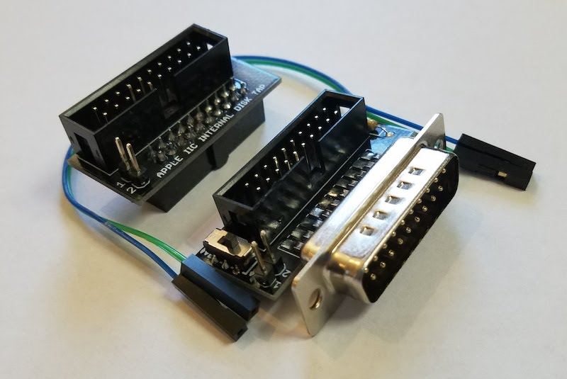
BMOW’s Internal/External Drive Switcher for Apple IIc is back in stock! Select which 5.25 inch floppy drive should act as bootable Drive 1: the external Floppy Emu disk emulator or the IIc’s internal floppy drive. The Switcher also adds IIc support for Floppy Emu’s new dual external 5.25 inch floppy drive emulation feature.
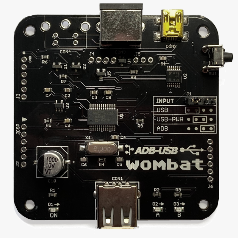
The Wombat keyboard/mouse converter is also back in stock. Connect modern USB keyboards and mice to a classic ADB-based Macintosh, Apple IIgs, or NeXT. Or connect legacy ADB input hardware to a USB-based computer running Windows, OSX, or Linux.
Both products were delayed by parts availability problems, shipping problems, and COVID lockdowns in China. It’s a difficult time for small-scale manufacturing! Grab your hardware today before these are gone again.
Be the first to comment!The Amazing Disk II Controller Card

In the world of Apple II disks, there are two major types of disk controller cards: the original Disk II controller (and clones), and everything else. Both have their place. The “everything else” category includes the Apple 3.5 disk controller card, Liron card, SCSI cards, IDE cards, and more. These cards provide a standard API for software to read/write blocks, get drive status, and format the disk, all without requiring the software to know anything about how the disk actually works. These cards have built-in smarts to handle the low-level details. In contrast the original Disk II controller card is dumb as dirt, and forces the software to handle virtually all of the low-level details. And yet it’s an amazing piece of technology for its time.
The first Apple II models had no built-in floppy disk support. The Disk II controller was cleverly designed to add that missing support at a very low cost, and was a major reason why Apple II computers became so popular. This disk controller was simpler, and cheaper, and more flexible, and just all-around better than any of its contemporary competition. It’s the ultimate example of Woz can-do technology.
Floppy Disk 101
A floppy disk is just a plastic circle with a magnetic coating. Loaded into a drive, the disk rotates at about 300 RPM. A stepper motor moves the read/write head linearly from the center of the disk to the outer rim. This arrangement provides for a few dozen concentric rings where a serial stream of 1s and 0s can be stored.

How do you get from these basics to higher-level concepts like bytes, tracks, and sectors? How are logical data bytes encoded into bit patterns on the disk? When reading the disk, how are the bits framed into bytes? How do you find track zero, or the boundaries between sectors? The conventional answer to these questions in the 1970s was extra hardware, and lots of it. This made the disk controllers and the drives themselves complex and expensive, putting them mostly out-of-reach for an inexpensive home computer system.
It was late 1977 when Apple set its sights on finding an alternative to cassette tape data storage, and began looking into options for a floppy drive for the Apple II. They were still a small and unproven company, and the Apple II had only been available for about six months. Woz didn’t know much about the subject of floppy disks, but he agreed to take on the challenge.
Woz’s approach was to remove virtually all of the hardware that controls the disk, and take a software-driven approach akin to bit-banging. Apple went to Shugart, the inventors of the 5.25 inch floppy drive, and requested a stripped-down version of Shugart’s SA400 drive with most of the control electronics removed. It was just a simple mechanism with one motor for spinning the disk and a stepper motor for moving the read/write head. As the legend goes, the entire Disk II hardware design was conceived and built by Woz and Randy Wigginton over a few weeks during Christmas vacation 1977, including writing the first version of DOS, and the working disk drive was demoed at CES in January 1978. Additional help was provided by Apple engineers Cliff Huston and Wendell Sander. 40+ years later I’m amazed by how quickly this small team was able to make everything work.
A few years ago I asked Woz about the Disk II development, and he said this:
I have no idea how I came up with that incredible disk controller. I was good at creating anything in electronics, analog or digital. I had no prior experience of any kind, not even in classes, regarding disk hardware or software. So my thinking had to be from the ground up. I had to sense data coming from the disk and make decisions about 0’s and 1’s based on timing.
I had taken a graduate level course at Berkeley (although an undergrad, I only took grad courses in anything having to do with computers in any university) on state machines and thought of how I could use 2 simple low cost chips as a state machine to do this, sort of a minimal microprocessor hand-built. At the time I just knew that it would read and write data but I assumed that I was leaving out many ingredients of a disk controller due to not knowing what they did. I assumed this because my design took so few parts. But in the end, mine did more in some good ways, especially since it was in the computer and tied to software that could alter how it worked, which eventually led to greater storage and faster speed that would not have been possible using the normal disk. Plus, I took about 20 chips off the drive itself and bypassed them from my own controller, because they were just middlemen that got in the way of things.
The best work I did, over and over, was partly due to not having money and having to learn how to use the fewest parts of anyone, and also due to the fact that everything great I created I had never done before.
A Tour Of The Disk II Controller
The Disk II controller card is basically just a fancy shift register. It knows how to read and write bits at a fixed rate of 1 bit every 4 microseconds. The card also has a tiny 256 byte ROM containing bootstrap code that runs when the computer first turns on. It’s a minimal 6502 program with just enough smarts to locate track 0, sector 0, load it into the computer’s memory, and then execute it. Every other aspect of disk control is handled by software.
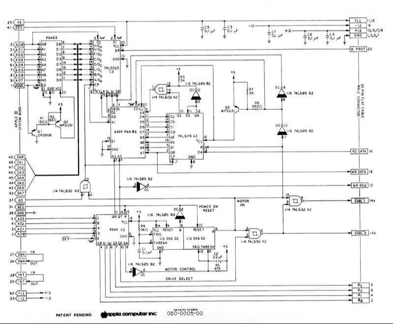
The card contains only eight simple chips. There’s a 256 byte ROM containing the bootstrap code, and a second 256 byte ROM used as part of a state machine (more on this in a moment). There’s also a 74LS174 hex flip flop providing the inputs for the state machine. A 74LS323 eight bit shift register is the heart of the whole design. A 74LS259 addressable latch stores the desired state of the motors and the drive 1 or 2 selection. There’s a 556 dual timer, and a 74LS05 hex inverter and 74LS132 quad NAND to provide some needed glue logic. That’s it. That’s the entire disk controller. Here’s the schematic:
Let’s go through the challenges of floppy disk I/O one at a time, and look at how the Disk II controller design solved them.
Challenge #1: byte framing. The data coming from the disk is a continuous stream of 1s and 0s, and there are no start or stop bits. So how do you know where one byte ends and the next byte begins? Woz’s solution was to require that every byte written to the disk have 1 as the most significant bit. During a disk read, the state machine takes bits from the disk one at a time, moving the shift register one position left and appending the new bit at the right. It keeps going until the left-most bit position holds a 1, at which point the state machine says “Aha! Here is a complete byte!” Then the CPU stores the byte, and the process begins again. The state machine clears the shift register after the MSB becomes 1, so it’s ready to shift in the eight bits for the next byte.
By itself this solution isn’t enough. If the state machine starts reading bits in what was actually the middle of a byte, it will probably misinterpret a 1 bit in the middle of the byte as being the 1 bit for the MSB position. But this scheme ensures that if the state machine gets the byte framing correct just once, whether by luck or another method, it will continue to be correct from then on. So the challenge is finding a way to guarantee the framing is correct before beginning to read disk data.
The conventional solution is to write a special 50-bit pattern of so-called sync bytes to the disk, immediately before each sector. These aren’t really bytes at all, but a 10-bit pattern 1111111100 repeated five times. This pattern has the interesting property that no matter where the byte framing is initially, it will fall into correct synchronization after at most five repetitions of the pattern, just by following the state machine rules described previously. This solution is entirely software-driven, and is merely a convention. The hardware itself has no mechanism to guarantee correct byte framing. There are other methods of ensuring framing, and some of the bizarre richness of Apple II copy-protection schemes arises from different approaches to framing taken by the custom I/O routines in many games.
Challenge #2: byte encoding. If every byte written to disk must have 1 as the MSB, then how do you write a zero byte, or any other byte with a value less than 128? And there are other restrictions too: every byte written to disk must have no more than two consecutive zero bits. If there are three consecutive zero bits, the disk hardware can’t reliably read back the data. Given these two requirements, there are only 66 possible 8-bit values that are permitted to be written to the disk. How then can arbitrary 8-bit values be stored?
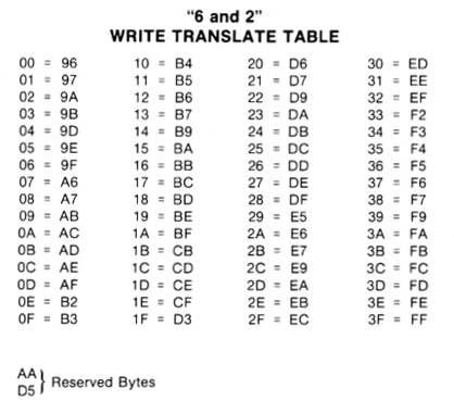
The answer is to split up the logical 8-bit bytes, and store their bits in subgroups as part of multiple disk bytes. The standard way of doing this is a GCR encoding scheme called 6-and-2. With 66 possible values for the disk byte, and two reserved values, that leaves 64 possible disk bytes for encoding data. 64 is 2 to the 6th power, so six logical bits can be encoded in every disk byte. A series of three disk bytes can encode the first six bits of three logical bytes, and a final fourth disk byte can encode the last two bits of the three logical bytes, concatenated together. This means the number of bytes stored on disk is 4/3 times the number of logical bytes, ignoring headers and checksums and padding.
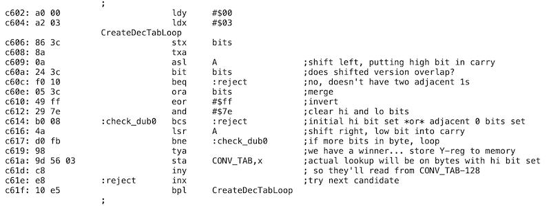
You might wonder how the Disk II controller bootstrap code accomplishes the GCR decoding for sector 0, track 0. At first glance, it would seem to require storing a 64-entry reverse lookup table in ROM, which is already one quarter of the very limited ROM space available. The bootstrap code actually uses a much cleverer solution, and constructs a 256-entry forward lookup table in RAM on the fly, using only 30 bytes of 6502 code!
The Apple II floppy byte encoding has evolved over time, resulting in a changing number of sectors and total disk capacity. The first version of the Disk II controller card didn’t permit any consecutive zeroes to be written to the disk. This further limited the number of possible disk bytes, and forced the use of a less efficient 5-and-3 encoding scheme. It was only possible to fit 13 sectors per track, resulting in 114 KB total disk capacity. Apple DOS 3.1 and 3.2 used the 5-and-3 scheme. Eventually Woz or one of his teammates realized that with a small change to the state machine, it would be possible to read two consecutive zeroes reliably. All it required was a change to the contents of the state machine ROM, essentially fixing a small bug in order to make the bit timing measurements more reliable. No hardware changes were needed to the Disk II controller. The more efficient 6-and-2 scheme was introduced beginning with DOS 3.3, ushering in the 16 sector tracks and 140K disks we’re familiar with now.
As with the byte framing, this whole encoding scheme is purely a software convention. There’s nothing about the hardware that implements 6-and-2 or 5-and-3 or any other encoding method. Sector 0 track 0 must be encoded using 6-and-2, because that’s what the ROM bootstrap code expects, but after that anything goes. Software is free to use any other encoding scheme it wishes, and many copy-protected programs use novel encoding schemes in order to obfuscate their workings.
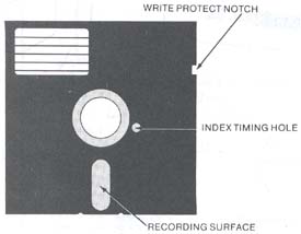
Challenge #3: sectoring. Once you’ve got the bitstream correctly framed into disk bytes, and the disk bytes correctly decoded into logical bytes, how do you make any sense of the data? It’s a ring buffer, so how do you know where the data begins and ends? 1970s floppy disks often used one or more small holes punched in the disk at regular intervals around the circumference. A small opening was cut in the disk’s dust jacket in order to reveal the index holes as they passed underneath. Hardware inside the disk drive sensed when these holes passed by as the disk rotated, and this information was used to determine where a new track or new sector began.
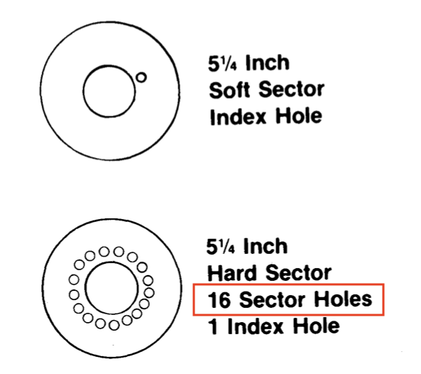
It’s easy to see why this might be undesirable. The hole-sensing hardware adds extra complexity and cost. And in the case of hard-sectored floppies with a hole for every sector, the number of sectors becomes part of the hardware design and can’t be changed. Apple’s move from 13-sector to 16-sector format would have been impossible with hard-sectored disks.
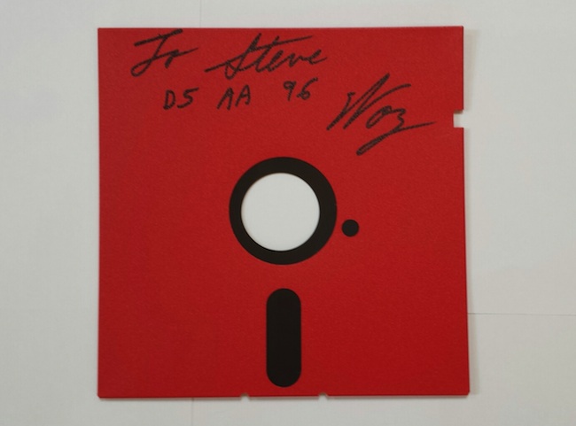
The Disk II design takes a software-driven approach to sectoring. Any index holes on the disk are ignored. When it wants to find a particular sector on the current track, the computer begins reading bytes, ignoring everything it sees until it finds the three-byte sequence D5 AA 96. This signature marks the beginning of a new sector on the disk, and is possibly the most famous byte sequence in the entire kingdom of Apple II arcana. On the wall of my office hangs a 5.25 inch floppy disk with a D5 AA 96 greeting signed by Woz himself:
A short sector header follows this signature, and among other things the header contains the sector number. If it’s the sector number the computer was looking for, then it reads the bytes that follow. If it’s not the right sector, then it keeps looking for another D5 AA 96 to indicate the beginning of the next sector, and tries again.
This whole business is – you guessed it – purely a software convention. The D5 AA 96 signature, the sector header, the length of sectors, and everything else are merely conventions. There’s nothing whatsoever about the Disk II controller card hardware that requires software to work this way, and some software takes a different approach. One well-known example was the game Prince of Persia, which used a custom scheme called RWTS18 that was optimized for reading as opposed to writing, and used six 768-byte sectors per track instead of the standard sixteen 256-byte sectors.
Challenge #4: finding tracks. So far we’ve only discussed data in a single one of the concentric rings on the disk. These rings are usually called tracks, but as we’ll see, the definition of exactly what constitutes a track can sometimes be fuzzy. So how do you switch between tracks, or locate a specific track? And just how many tracks are there? The Disk II and its controller hardware don’t answer these questions. Instead, it’s all (say it with me now) software-driven.
On the disk media there’s no such thing as a track – it’s just a featureless round expanse of magnetic media. Tracks are created when the read/write head remains at a fixed radial position while the disk spins underneath and bits are written. Then the head moves inward or outward to a new radial position, and writes a new track.
The head movement is controlled by a stepper motor, under direct software control. The stepper consists of four electromagnets, and at any moment the software can turn any of them on or off. A series of permanent magnets are attached to a gear that moves the read/write head, and by activating the electromagnets in the right sequence, they can attract or repel the permanent magnets and move the head. If stepper electromagnet 0 was on, and then electromagnet 1 is turned on and electromagnet 0 turned off, the head will move a small radial distance. Then if electromagnet 2 is turned on and electromagnet 1 turned off, the head will move further in the same direction.
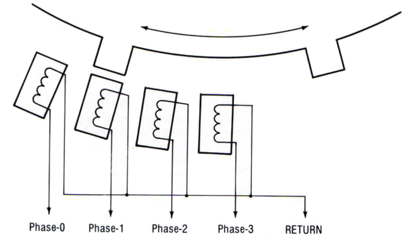
How closely can you space the tracks? It turns out that two of these head movements are normally needed in order to move the head far enough so that a track won’t interfere with its neighbors. If you try to write tracks with only one head movement between them, the magnetized areas of the disk media from the adjacent tracks will bleed into each other and cause a mess. For this reason, two movements are normally considered to be equal to one track, and a single movement is a half track. Quarter tracks are also possible, but aren’t used by most software. If electromagnet 0 was on, and then electromagnet 1 is also turned on, the head will move a quarter track. If electromagnet 0 is then turned off, the head will move an additional quarter track.
The method of locating track 0 is as crude as can be. The disk controller doesn’t know at what track the read/write head is currently located, so software must activate the stepper motors in sequence in order to move the head continuously in the direction of track 0. Eventually the head will reach track 0 and can move no further, but the software will keep activating the stepper motors, driving the head against a mechanical stop and producing the familiar rat-a-tat sound of an Apple II floppy drive during boot-up. After 80 half steps, the head is guaranteed to be at track 0. From that point on the software must keep track of all stepping movements, and remember what track the head is currently on, in order to perform relative steps. If the software gets confused, say by reading what it thinks is track 20 but finding data for a different track there, it will usually recalibrate by repeating the track 0 seek and then immediately stepping back to the desired track. This creates a clack-clack sound that many long-time Apple II users will recognize as the sign of a failing disk.
It’s customary to store 35 tracks per disk, but this is merely a convention. The true limit varies slightly from one drive to the next, and is determined by the maximum and minimum linear positions of the read/write head. Non-standard disks with up to 40 tracks are sometimes seen.
Copy-protected Apple II games very often play funny tricks with track stepping. A simple trick is locating a track at some odd number of half-steps from track 0. Tracks must be at least two half steps apart, but there’s no rule saying they can’t be three half steps apart, so you might find a game disk with data on tracks 0, 1, 2.5 and 4. This will confuse disk copy programs that only expect to find data on integer numbered tracks.
A more advanced trick is writing data on two tracks that are just a half step apart, but only using half the circumference of the disk for each track, so the magnetized areas won’t interfere with each other. There might be a half-track’s worth of data at track 2 from twelve o’clock to six o’clock around the disk, and then another half-track’s worth of data at track 2.5 from six o’clock back around to twelve o’clock. Data that’s written this way is easy to read, but is difficult to write without specially-crafted routines, making disk copies difficult.
Bootstrap Code Disassembly
A disassembly and analysis of the 256-byte bootstrap routine is fascinating. Starting with literally nothing, this code must bang directly on soft switches to control the stepper and read the shift register. It must activate the stepper electromagnets in the right pattern to reach track zero, and then begin reading bytes. It must recognize the D5 AA 96 signature, and check to see if it has the right sector. It must use a GCR decode table which it constructs on-the-fly in order to convert disk bytes. It must perform 6-and-2 decoding to reconstruct three logical bytes from four disk bytes, load the whole sector into a RAM buffer, and then jump to the just-loaded code. And all of this in only 256 bytes!
Woz gets the job done with five bytes to spare, and only about 100 lines of 6502 assembly code. But due to space constraints, some features were omitted. The Disk II controller bootstrap code doesn’t verify the checksum on sector 0, something that was “fixed” in later disk controllers but caused incompatibility with some games. There’s also no error handling, so the bootstrap code will keep trying forever to load sector 0. This explains why an Apple II with Disk II controller card appears to hang during booting if there’s no disk in the drive, or a bad disk, rather than show a nice error message like the Apple IIc or IIgs.
Disk II Controller Hardware Design
This discussion has focused on what the Disk II controller does, without going into much detail about precisely how it does it, and how those eight chips are used. For an excellent and very thorough breakdown I recommend reading Chapter 9 of Understanding the Apple II by Jim Sather. It goes into additional detail about the flux patterns on the disk and much more.
The design of the state machine is quite interesting, and I haven’t seen it described anywhere other than in Sather’s book. Anyone who remembers concepts like Mealy and Moore state machines from a long-ago class will recognize Woz’s work. The state machine ROM is just a simple lookup table. Its inputs are the current state, the read/write mode, the MSB of the shift register, and the next bit coming from the disk. The outputs are the next state and a set of control signals. Depending on the control signals, the state machine may shift the value in the shift register and append a zero or one bit, or clear the shift register, or parallel load the shift register from the data bus.
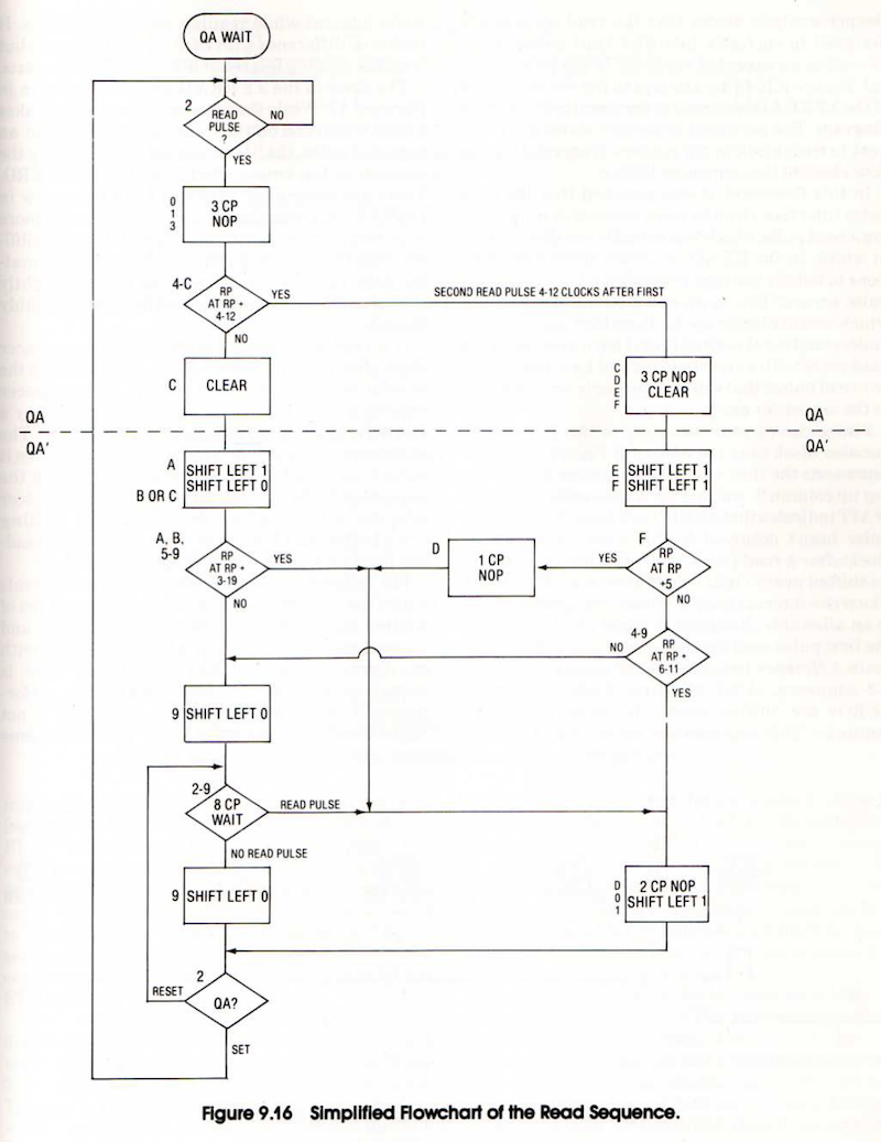
The state encodings are carefully chosen such that state bits can double as control bits. For example, when writing data to the disk, the value on the write head is also the most significant bit of the current state number. When reading data from the disk, the state sequences are chosen so as to frame pulses corresponding to 1 bits into an appropriate 4 microsecond window, and insert zero bits whenever 1.5 bit windows (6 microseconds) have elapsed without seeing a pulse. For my Yellowstone FPGA-based disk controller I’ve implemented the equivalent functionality in a hundred lines of Verilog; Woz did it with a 256-byte ROM and a hex flip-flop.
Putting It All Together
The words “software-driven” have come up again and again here, and that’s the theme of the Disk II controller. It enables a very flexible design using minimal hardware, but it pushes a tremendous amount of complexity onto the software. Modern software designers might call this bad practice, and would prefer to see that complexity abstracted away behind a standard interface, so the software only has to be concerned with actions like “read block 31”. And that’s exactly how all other Apple II disk controllers work. But in order to work with a Disk II controller, software like DOS 3.3, ProDOS, and most games need to include tons of extra code for manipulating the stepper, locating sectors, performing GCR decoding, and the whole kitchen sink. It’s a little bit crazy, but it works.
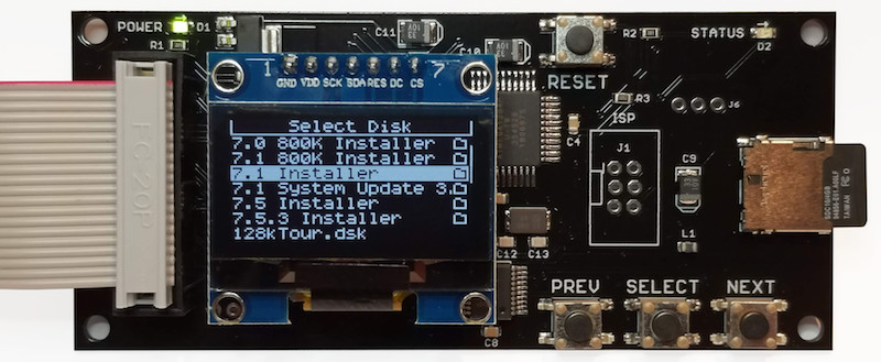
If you’ve read this far, you may be interested in the BMOW Floppy Emu disk emulator. Collectors of old Apple II, Macintosh, or Lisa computers will find the Floppy Emu invaluable for running software downloaded from the web, and transferring files between vintage and modern machines. The Floppy Emu stores hundreds of disk images on an SD memory card, and uses custom hardware to mimic many different kinds of Apple floppy disk drives and hard drives. Read more about it here.
During the 10+ years I’ve spent delving into every aspect of Apple’s disk drive designs, it’s been a remarkable journey. Years ago I used to think I understood how it all worked, but today I realize I hardly knew anything at all. Now I believe I’ve got everything mapped out, but of course there are probably still holes in my understanding that I’m blind to. Did I explain anything incorrectly here, or forget to mention something important? Let’s hear about it. Please leave a comment below.
Read 9 comments and join the conversationFloppy Emu Update: Smartport and More

Hello! I’m Alice, the engineering intern here at Big Mess o’ Wires. I’m a math with computer science major at UC San Diego, and throughout the summer I’ve been working on some fixes and improvements for BMOW products. I started out on the ADB-USB Wombat, but most of my work has been on Floppy Emu development.
Today, I’m excited to finally share what I’ve been doing! Here is a collection of some of the new Floppy Emu improvements. They’re mostly related to Smartport and Unidisk 3.5 emulation for the Apple II, but there’s some other good stuff too.
Smartport Hard Disk and Unidisk 3.5 emulation:
– Control commands are now handled better. This resolves GS/OS freezes during shutdown or restart, and related problems with other software.
– A NAK/retry mechanism was added for cases where there’s a checksum failure on a Read or Status command. It will provide more robustness against signal noise.
– Status commands that request invalid or unsupported status types will now receive a proper error reply.
Unidisk 3.5 emulation:
– Emulation now continues to run even while displaying the disk selection menu. It will respond to commands as an empty drive, instead of not responding at all. This resolves some potential problems when booting from other disks and when swapping disks.
– Handling of disk ejection has been improved. Disks can now be ejected and replaced through the GS/OS Finder menu and other methods of software-controlled disk eject, as well as through the Floppy Emu menu interface.
– The disk icon that’s displayed in GS/OS has been updated to look like a 3.5 inch floppy disk.
General improvements:
– Occasional errors CHECK PIN CLKO-L and CHECK PIN RESET should no longer occur.
– Hidden system directories on the SD card will not be displayed in the disk selection menu, including Windows 10’s “System Volume Information” directory.
– OLED screen dimming behavior is now more consistent.
These improvements are available in firmware versions 0.2T-F30, 0.2S-F29-SPDC, 0.2S-F26, and 0.2H-F15 (depending on the Floppy Emu model and the type of computer it’s used with). You can download the new firmware files on the Floppy Emu page. Let us know if you run into any issues, and have fun!
Read 6 comments and join the conversationNew Cases for the Daisy Chainer!
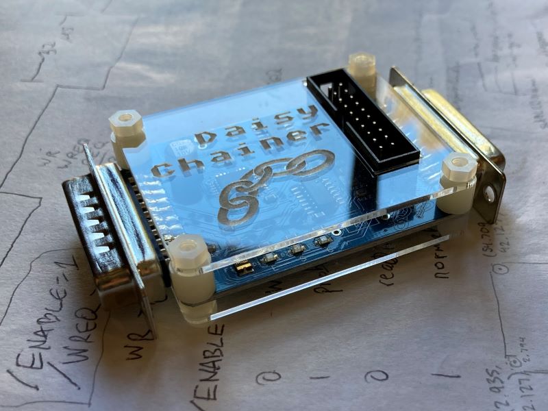
Hello! If you haven’t met me already, I’m Alice, the BMOW engineering intern. (You might hear more about what I’ve been up to soon.) I’m excited to share that after several stages of redesign, cases for the Daisy Chainer are finally here! These clear acrylic enclosures will protect your Daisy Chainer and show it off with style. This is a plate style case similar to the ADB-USB Wombat with open sides and a logo-etched top. Available now on the store!
Dark Castle Bugs
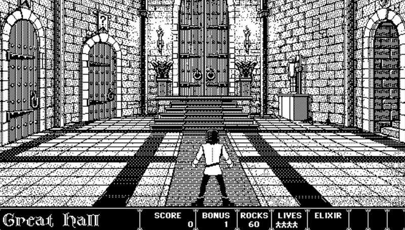
Here’s a brief follow-up about the classic Macintosh game Dark Castle, which I mentioned a few weeks ago in connection with some possible disk emulation bugs. This game originally shipped on two 400K floppy disks. At the intro screen shown above, the player is given a choice of doors, and some of the doors will ask the player to insert disk 2. But when loading the 400K game disk with a Floppy Emu disk emulator, the disk swapping doesn’t work. Disk 1 doesn’t get ejected, and if disk 2 is inserted, it will be ignored. A few weeks ago I speculated that this may be caused by a Floppy Emu bug, but I was wrong.
After a bit of research, I found that the problem is just another example of Games That Only Work In Drive 1. This is pretty common in the Apple II world, but not so common for Macintosh games. When Dark Castle tries to eject disk 1, it specifically tells drive 1 (the internal drive) to eject, regardless of which drive contains the disk. Then it checks the same drive for disk 2. Since Floppy Emu is normally connected to classic Macs as the external drive (drive 2), this doesn’t work. To confirm this behavior, I disassembled an old Mac and connected a Floppy Emu internally, in place of the built-in floppy drive. With this configuration, Dark Castle 400K worked fine.
BMOW’s Vintage Apple Software Collection SD Card has an 800K version of Dark Castle, where the contents of both 400K disks have been copied onto a single 800K disk. This avoids the need for disk swapping, so the game can be played normally from a Floppy Emu or other external floppy drive, but it requires a Macintosh model that’s compatible with 800K drives. The oldest Macintosh models are only compatible with 400K drives. For those models, playing Dark Castle will require connecting the Floppy Emu internally as I did, or copying the disk images from the Floppy Emu onto real 400K disk media for use in the internal floppy drive.
Be the first to comment!New Product Release: Dual 5.25 Adapter for Disk II, and Apple IIc Drive Switcher 2.0
Today Big Mess o’ Wires is releasing two new products for use with the BMOW Floppy Emu disk emulator for Apple computers. Remember the dual 5.25 inch floppy emulation mode that was announced back in February? It gave the Floppy Emu Model C hardware the ability to emulate two 5.25 inch drives at once, which is great for two-disk games and for reducing disk swapping. But sadly the Apple IIc and the Disk II Interface Controller card both lack the I/O signals required to control two drives over one cable. I hinted that adapter solutions might be coming soon; now here they are!
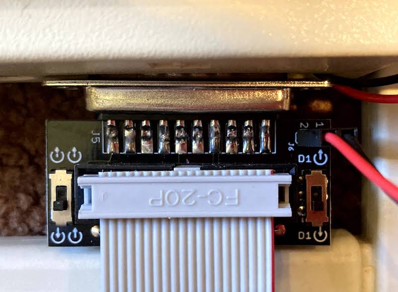
The Internal/External Drive Switcher is a two-piece adapter for the Apple IIc, providing an easy way to select which floppy drive will act as Drive 1. This new version 2.0 of the Switcher also adds optional support for dual 5.25 inch floppy emulation. Like the original 1.0 version, it’s a great convenience option for the IIc, which normally can only boot from its internal 5.25 inch floppy drive. Now IIc owners have three options:
| BEHAVIOR | SWITCH ONE | SWITCH TWO |
|---|---|---|
| Swapped Mode Drive 1 is external, Drive 2 is internal |
 |
 |
| Normal Mode Drive 1 is internal, Drive 2 is external, default Apple IIc behavior |
 |
|
| Dual External 5.25 Mode Drive 1 and Drive 2 are external, requires Floppy Emu Model C configured for Dual 5.25 emulation mode |
|
 |
| Invalid setting, do not use | |
|
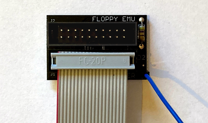
The Dual 5.25 Adapter for Disk II Interface Card works with the venerable Apple disk controller card found in most Apple II Plus and IIe computers. This disk controller card has two separate 10 x 2 pin rectangular connectors for two separate drives, instead of supporting two daisy-chained drives on a single cable like the later Apple II models. The Dual 5.25 Adapter takes all the I/O signals from the card’s Drive 1 connector, plus a single enable signal from the card’s Drive 2 connector, and merges them together for use by the Floppy Emu. Hello dual 5.25!
Both products are available now at the BMOW Store.
Read 4 comments and join the conversation