

Archive for the 'RC Vehicles' Category
RC Servo Signal Decoder, Part 2
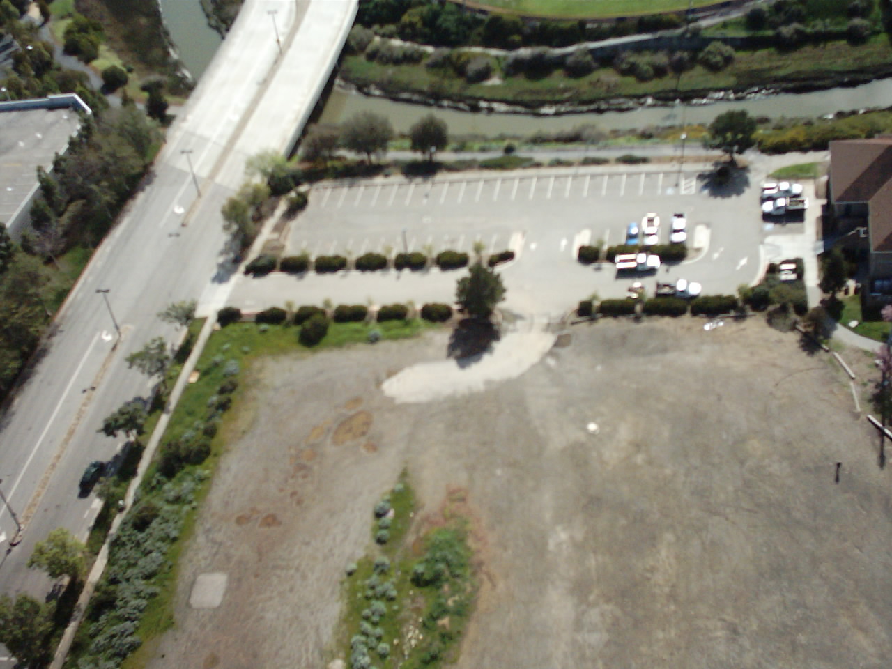
It works! I’ve continued poking away at this circuit to decode an RC airplane servo signal and trigger a camera shutter during flight, and I’m happy to report success!Once I switched to using the CD4013 flip-flop with a positive logic clear input instead of negative logic, it was a piece of cake. I have to say, living just a mile from one of the USA’s largest electronics dealers (Jameco) is pretty sweet. I can hit their web site and place an order for practically any obscure electronic component I can think of, then cruise down to their offices and pick it up from the will-call desk an hour later. Nice!I rebuilt the decoder circuit that I discussed last time, soldering everything together “dead bug” style. This was necessary in order to keep everything as small as possible, so I could fit it inside the camera body. I forgot to take a photo before I closed everything up, but it looks very similar to this example from laureanno.com: When I first connected the servo, decoder, and camera, it didn’t work. Nothing happened when I toggled the switch on my RC transmitter. Setting up the oscilloscope again, I was able to see that the reference pulse width generated by the RC circuit I’d built was about twice as long as it should have been. I’m not sure how that happened, even with 20% tolerance components, but I was able to quickly swap in a different value resistor, and get it working perfectly. Then with a bit of creative packing, I managed to cram it all back inside the camera body.Today during my lunch hour, I was able to try it out for the first time. The shutter trigger worked fabulously! I wish I could say the same for the quality of the pictures, but unfortunately the focus wasn’t set quite right, and the photos are a little blurry. They’re still pretty fun to look at though. I was flying next to the headquarters of Oracle Corporation in Redwood City, California. Those are the clustered cylinder-shaped mirrored buildings you see in the photos. The plane looks like it was a little higher than the tallest building, which I think is 20 stories tall. See if you can find me in some of the photos!Click any of the thumbnails below to see the full-sized version.


 February 27 Edit: I corrected the focus problem, and tried again. Unfortunately I got the propeller in some of the shots, and this new set wasn’t from as high an altitude. But I did get some great shots of the bay, an aerial self-portrait, and a flock of Canada geese.


RC Servo Signal Decoder for Camera Shutter Switch
Hey, I’m back. I think my oscilloscope made me do it. For the past six months I’ve been working with RC airplanes, not doing any electronics work. The oscilloscope has been taking up space on my desk while it sits untouched, gathering dust. Last week I finally decided I was never going to use it again, and packed it away in a closet. But that got me to thinking about electronics again, and about what kind of projects I could do related to RC. So after just a few days, the oscilloscope has returned from its closet banishment and is in use once more for a new project.
I recently bought an Aiptek SD 1.3 megapixel camera, with the idea to mount it on the fuselage of one of my planes, and do some aerial photography. The Aiptek weighs just 52 grams (about 2 ounces), and so it won’t weigh down the plane excessively. But the tricky part is finding a way to activate the shutter while the plane is in the air. It turns out that this is mostly a solved problem, and it’s possible to build a circuit to decode the servo signal from an unused receiver channel, creating a 0 or 1 pulse depending on the position of a transmitter switch or stick. Then by hacking into the camera guts and a bit of soldering, that pulse can be used to trigger the shutter.
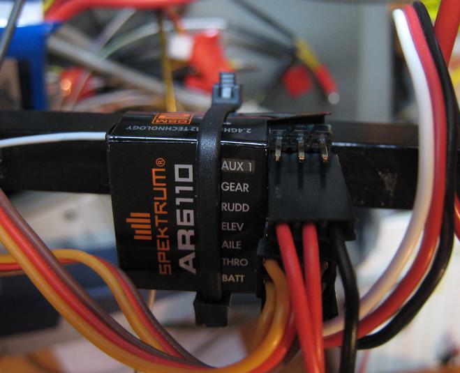
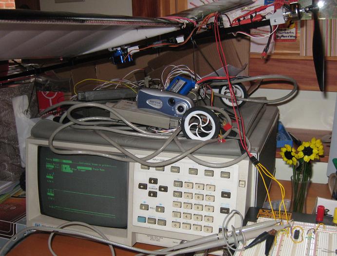
Here’s one of my planes (a GWS Slow Stick), with three spare wires hooked into the receiver’s “gear” channel (which I don’t normally use), connected to the oscilloscope and a growing circuit on the protoboard. It turns out that these servo signals for the channels are ideal for hacking with digital logic. Of the three wires connected to the receiver, one is ground, one is a regulated +5 volts, and one is a modulated position signal that indicates the desired position for that channel (rudder, elevator, aileron, flaps, gear, whatever). The connectors are even standard 0.1 inch male headers. What could be easier?
I examined the servo signal with the oscilloscope. It’s a regular pulse train with a 22ms period. The width of the pulse varies depending on the desired position for the channel. The width is about 1.2ms at the minimum position, and 2ms at the maximum position. Taking 1.6ms as the midpoint, what’s needed is a circuit that outputs 0 if the pulse width is less than 1.6ms, and 1 if it’s greater than 1.6ms. This could be done many different ways: the first two that come to mind are a small microcontroller, or a low-pass filter that turns the servo signal into a DC voltage, and compares it to a reference voltage.
I’ve decided to follow another example I found, which I thought was especially clever. It uses just two flip-flops and a couple of passive components. You can check out the circuit schematic for the details. The servo signal pulse train is used to clock the first flip-flop. It’s D input is tied high. When it’s clocked, its Q output goes high, which begins to charge an RC circuit. When the capacitor voltage gets high enough, it activates the asynchronous reset, clearing the Q output. The complementary /Q output is used to clock the second flip-flop, whose D input is the servo signal. If the RC time constant is chosen correctly, then the second flip-flop will be clocked 1.6ms after the first one, sampling the servo signal at that time. If the pulse width is less than 1.6ms it will sample a 0, otherwise it will sample a 1. Pretty neat!
My only headache is that I don’t have the 4013 CMOS flip-flop called for in the circuit. I do have lots of 74LS74 flip-flops, which are similar, but are TTL designs with an active low asynchronous reset instead of active high. I’d thought it would be simple to modify the circuit to work with an active low reset, but after a couple of hours of futzing around with it, I concluded that it’s either not possible, or I’m just not smart enough. I started by swapping the positions of the resistor and capacitor, but the circuit initializes in the reset state and never exits it. And even if I found a solution to that, the input current on this LS series chip is so high, that with a 10K resistor to ground, the voltage at the input pin is actually pulled up to 2 volts! Ack! I decided I’ll just buy a 4013 for a few cents, and stop banging my head.
Read 5 comments and join the conversation