

Cortex M3 For Dummies – STM32 Discovery Board
The ARM Cortex M3 has generated lots of buzz lately. Maybe you’ve been working with Arduinos, AVRs, or PICs for a while, and heard about the Cortex M3, but weren’t sure what it was all about or whether it was even relevant to you. This review will try to shed some light on the Cortex M3’s capabilities and development tools, using the STM32VLDiscovery board from ST Microelectronics.
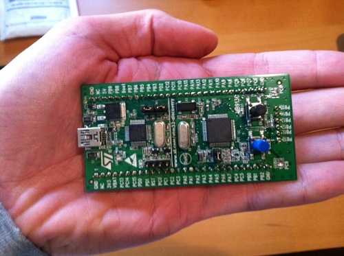
The nice folks at Newark sent me a STM32VLDiscovery Cortex M3 evaluation board for review. This little board packs a big bunch for a remarkably low price. It can be found for under $10 if you hunt around for a deal, which is an amazing value. ST is also currently running a promotion in which residents of the USA and Canada can get a free STM32F4Discovery board, which is similar to the board reviewed here.
Although the STM32 Discovery board isn’t marketed as an Arduino competitor, it could be one. Its size, layout, and functionality make it a reasonable replacement for many applications needing a small microcontroller board with lots of I/Os for experiments and mad scientist projects. To help put its specs into context, I’ve selected a few other boards that readers may be familiar with for comparison purposes. All the boards contain a microcontroller along with one or two buttons and LEDs, with I/Os connected to hobbyist-friendly 0.1 inch headers, and can be programmed with a plain USB cable. In addition to the STM32 Discovery, they are the Arduino Uno, Arduino Mega 2560, and Copper AVR32.
| STM32VL Discovery | Arduino Uno | Arduino Mega 2560 | Copper AVR32 | |
| Price | $10 | $25 | $50 | $38 |
| Processor | STM32F100 Cortex-M3 | ATmega328P AVR | ATmega2560 AVR | AT32UC3B1256 AVR |
| Type | 32 bit | 8 bit | 8 bit | 32 bit |
| Flash (KB) | 128 | 32 | 256 | 256 |
| EEPROM (KB) | 0 | 1 | 4 | 0 |
| RAM (KB) | 8 | 2 | 8 | 32 |
| Max Speed (MHz) | 24 | 20 | 16 | 60 |
| Voltage (V) | 2.0 – 3.6 | 1.8 – 5.5 | 1.8 – 5.5 | 3.0 – 3.6 |
| User I/O Pins | 51 | 20 | 70 | 28 |
| SPI channels | 2 | 2 | 5 | 3 |
| I2C channels | 2 | 1 | 1 | 1 |
| UART channels | 3 | 1 | 4 | 2 |
| ADC channels | 16 | 8 | 16 | 6 |
| DAC channels | 2 | 0 | 0 | 0 |
| USB | no | no | no | yes |
The table makes it clear that you’re getting a lot of microcontroller for your money. ST is very likely selling these boards at a loss, because their goals are different than the makers of the other boards. ST isn’t trying to sell you a prototyping product, but rather they’re trying to get you familiar with their line of STM32 microcontrollers so you’ll go on to incorporate them into a product of your own design. To appreciate this, it’s necessary to understand the ARM Model that gave rise to the Cortex M3.
The ARM Model
The Cortex M3 and other ARM processors were designed by ARM Holdings, a British semiconductor company. ARM doesn’t actually manufacture the processors they design, but instead they license the designs to other semiconductor companies, who then turn them into specific chips and sell them under their own brand names. Thus ST’s STM32 line of microcontrollers, Texas Instruments’ Stellaris line, NXP’s LPC1000 line, Atmel’s AT91SAMxx line, and many others are all Cortex M3 microcontrollers. All use the same instruction set, and have very similar features, so you could find a chip in any of those lines that’s a near functional equivalent of the STM32F100RB chip on the Discovery board. The chips aren’t exact clones, however. They differ in the amount of on-chip memory, clock speeds, pin configuration, peripheral units, and other features.
Unfortunately this is the Cortex M3’s biggest obstacle to gaining more traction in the electronics hobbyist community, because there isn’t really a “Cortex M3 community”. There’s a Stellaris community, and an LPCxxxx community, and an STM32 community, and so on. Each one is just different enough from the others to make manufacturer-independent tools and code sharing difficult. By fracturing the community into many different parts, it also makes it harder for it to reach a critical mass necessary to catch significant public interest in the way AVR and PIC have.
ARM Cortex M3
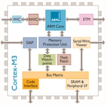
So what exactly is a Cortex M3? It’s a microcontroller, like an AVR or PIC. That means it has built-in Flash memory and RAM, lots of general-purpose I/O pins that can be controlled individually through software, and built-in peripherals for things like serial communication or analog-to-digital conversion. Where the Cortex M3 differs from 8-bit AVRs and PICs is that it’s a 32-bit processor, capable of running at speeds up to 100 MHz in some versions, and is a cousin of the higher-end ARM processors found in devices like Apple’s iPad and in some PCs. It also offers larger memories than typically found on AVR or PIC microcontrollers. In short, it’s like a beefed-up version of the micrcontroller you’re using now.
A few interesting features of the Cortex M3 aren’t found on typical 8-bit microcontrollers, like hardware divide support, an internal PLL for clock synthesis, and two digital to analog converters. The M3 also has a clever remappable pin feature, which lets you choose from among several options for which pins to use for I2C, SPI, USART, ADC, and other hardware units. This provides extra flexibility in board design and port usage.
The Cortex M3 has a newer sibling called the Cortex M0. The M0 is geared towards lower cost, lower power applications than the M3, but the two are very similar. Most of what you read about the M3 on the web also applies to the M0.
While it has arguably generated the most buzz lately, the Cortex M3 is by no means the only entry in the 32-bit high performance microcontroller market attempting to supplant 8-bit mcus like the AVR ATmega. Another example is the AVR32 chip, found on the Copper board. This 32-bit microcontroller is also made by Atmel, although it shares little with Atmel’s 8-bit microcontrollers beyond the AVR name.
The STM32VLDiscovery Board
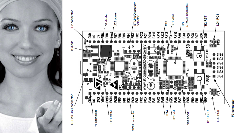
ST’s name for their Cortex M3 product line is STM32, and the STMVL32Discovery board is the smallest and least expensive of their Cortex M3 evaluation boards. Now who is this woman that appears on all of ST’s marketing materials for the STM32 line? Her photoshopped eyes look a bit disturbing. Some of their STM32 materials also use a rainbow-colored butterfly logo, which I like much better.
The STMVL32Discovery board is actually two boards in one: everything to the left of the vertical line in the above diagram is an ST-Link programming/debug module. It can be used with the Cortex M3 module on the right side of the board, or to program and debug a STM32 mcu on another board in a stand-alone application that lacks a programmer. I believe an earlier version of the ST Discovery board actually had perforations in the PCB so you could break-off the ST-Link module and use the two halves separately, but with the STMVL32Discovery there’s only a line in the silkscreen to remind you there are two functionally separate modules on a single board.
At roughly 3.3 x 1.7 inches, the board is smaller than a standard-size Arduino. Two rows of 0.1 inch header down the sides of the board make it easy to connect other components. The headers are on both the top and the bottom of the board, so you can make connections from either side, which is a nice touch. You could almost drop the ST Discovery right into a breadboard, except for the 6-pin header along its right edge. I’m not sure what ST was thinking here, because when inserted into a breadboard, these six pins will all be tied together in a single row. Depending on the layout of your breadboard, you may be able to insert the ST Discovery such that those six pins hang off the edge, unconnected.
Besides the Cortex M3 itself, the board also contains two user-controllable LEDs, a user push button, and a reset button. That’s similar to what you’ll find on an Arduino board, and is just enough to test things out and make sure it’s all working before connecting more components.
The board is powered over USB, or optionally from an external supply. When first connected to your PC, it immediately runs a demo program that flashes the LEDs in different patterns when you press the user push button. Under Windows it also automatically mounts itself as a read-only USB storage drive, which contains a few files with links to the online documentation. That’s pretty slick.
There’s no printed documentation included with the ST Discovery board, but the online user manual is quite well done. It includes a quick-start guide, block diagram, layout diagram, mechanical drawing, full schematics, explanation of all the jumpers and solder bridges, and a pin description table. The companion software package includes the libraries and header files for ST’s version of the Cortex M3 and for the ST Discovery board peripherals, as well as several example projects. On ST’s web site you’ll also find detailed tutorials for building and running the example projects using the three officially supported development toolchains.
ARM Development Tools

There are a bewildering number of development toolchain choices for ARM Cortex M3 development. It’s hard to overstate just how painful this makes the getting started process for a beginner. Worse still, the only officially-supported toolchains (IAR, Keil, and Atollic) are professional tools which are very expensive, and certainly won’t be of interest to any hobby developers. When their web page has a “get a quote” link instead of listing an actual price, that’s the clue to look elsewhere. For reference, the Keil tools cost $4895 for a single license, and the others are similar. Ouch!
The professional tools do all offer a time-limited trial version or a code size-limited version, but few hobbyists will be happy with those as a permanent solution.
If you’re willing to cough up a little money (but not $4895) for a well-made development tool with good support, Rowley Associates Crossworks is well-regarded and is just $150 for a personal license.
After looking at more than a dozen different development tools, I decided to put together my own toolchain based on the CodeSourcery CodeBench g++ Lite GNU command line tools and Eclipse C/C++ IDE. This excellent setup guide for Eclipse and CodeSourcery with STM32 describes the process in detail, so I won’t list all the setup steps here. Depending on your familiarity with other development environments and your tolerance for this sort of job, you may find the process anywhere from slightly tedious to completely impossible. It involves installing Eclipse, the Java runtime, CodeSourcery, GDB server, the STM32 SDK, and the ST-Link programming utility from six different sources, and then configuring them all to work together properly. It really makes you appreciate the convenience of a tool like Atmel’s AVR Studio, which performs all of the same functions in a single tool with a single download and install process. All together, it took me about 90 minutes to get the STM32 Cortex M3 development tools configured and program one of the example projects onto the ST Discovery board.
Cortex M3 Software Development
OK, let’s blink some LEDs. Here’s the simplest of the examples provided by ST:
#include "stm32f10x.h"
#include "STM32vldiscovery.h"
GPIO_InitTypeDef GPIO_InitStructure;void Delay(__IO uint32_t nCount);int main(void) { /* Configure all unused GPIO port pins in Analog Input mode (floating input trigger OFF), this will reduce the power consumption and increase the device immunity against EMI/EMC *************************************************/ RCC_APB2PeriphClockCmd(RCC_APB2Periph_GPIOA | RCC_APB2Periph_GPIOB | RCC_APB2Periph_GPIOC | RCC_APB2Periph_GPIOD | RCC_APB2Periph_GPIOE, ENABLE);GPIO_InitStructure.GPIO_Pin = GPIO_Pin_All; GPIO_InitStructure.GPIO_Mode = GPIO_Mode_AIN; GPIO_Init(GPIOA, &GPIO_InitStructure); GPIO_Init(GPIOB, &GPIO_InitStructure); GPIO_Init(GPIOC, &GPIO_InitStructure); GPIO_Init(GPIOD, &GPIO_InitStructure); GPIO_Init(GPIOE, &GPIO_InitStructure);RCC_APB2PeriphClockCmd(RCC_APB2Periph_GPIOA | RCC_APB2Periph_GPIOB | RCC_APB2Periph_GPIOC | RCC_APB2Periph_GPIOD | RCC_APB2Periph_GPIOE, DISABLE);/* Initialize Leds LD3 and LD4 mounted on STM32VLDISCOVERY board */ STM32vldiscovery_LEDInit(LED3); STM32vldiscovery_LEDInit(LED4);while (1) { /* Turn on LD2 and LD3 */ STM32vldiscovery_LEDOn(LED3); STM32vldiscovery_LEDOff(LED4); /* Insert delay */ Delay(0xAFFFFF);/* Turn off LD3 and LD4 */ STM32vldiscovery_LEDOff(LED3); STM32vldiscovery_LEDOn(LED4); /* Insert delay */ Delay(0xAFFFFF);} }void Delay(__IO uint32_t nCount) { for(; nCount != 0; nCount--); }
If you’ve previously developed software for other microcontrollers, then this probably looks fairly understandable. The first step is to configure all of the I/O pins as inputs, akin to setting the DDR (data direction) register on an AVR or calling pinMode() with the Arduino environment. In this case, the I/Os are configured by passing a struct to a function instead of directly twiddling some bits in a register, although it’s likely that the implementation of GPIO_Init() does something like that under the hood. That RCCABP2PeriphClockCmd() function looks a little strange, though– it appears the port’s clocks need to be explicitly enabled before configuration, then disabled afterwards.
The rest is just manipulation of the LEDs, but it’s a bit more abstract than most people are probably accustomed to seeing. You don’t normally need to initialize an LED or call a function to turn it on. These functions are provided by the ST Discovery board library to simplify development, but curious minds will want to know what they actually do. Here’s the implementation of STM32vldiscovery_LEDInit() and definitions of LED3 and LED4:
typedef enum
{
 LED3 = 0,
 LED4 = 1
} Led_TypeDef;
const uint32_t GPIO_CLK[LEDn] = {LED3_GPIO_CLK, LED4_GPIO_CLK};#define LED3_GPIO_CLK RCC_APB2Periph_GPIOC #define LED4_GPIO_CLK RCC_APB2Periph_GPIOCvoid STM32vldiscovery_LEDInit(Led_TypeDef Led) { GPIO_InitTypeDef GPIO_InitStructure; /* Enable the GPIO_LED Clock */ RCC_APB2PeriphClockCmd(GPIO_CLK[Led], ENABLE);/* Configure the GPIO_LED pin */ GPIO_InitStructure.GPIO_Pin = GPIO_PIN[Led]; GPIO_InitStructure.GPIO_Mode = GPIO_Mode_Out_PP; GPIO_InitStructure.GPIO_Speed = GPIO_Speed_50MHz; GPIO_Init(GPIO_PORT[Led], &GPIO_InitStructure); }
So STM32vldiscovery_LEDInit() enables the clock for port C, where the LEDs are connected, and then configures the correct pin in port C as an output. GPIO_Mode_Out_PP specifies a push-pull output, in other words a normal output that’s actively driven high and low. GPIO_Speed_50MHz controls the rise and fall times of the output signal. Selecting a faster speed will produce shorter rise and fall times, but will consume more current and generate more supply voltage swings and electrical noise.
Lastly, let’s take a look at STM32vldiscovery_LEDOn() and STM32vldiscovery_LEDOff():
void STM32vldiscovery_LEDOn(Led_TypeDef Led)
{
    GPIO_PORT[Led]->BSRR = GPIO_PIN[Led];
}
void STM32vldiscovery_LEDOff(Led_TypeDef Led) { GPIO_PORT[Led]->BRR = GPIO_PIN[Led]; }
Each port has a separate bit set (BSRR) and reset (BRR) register. Writing a 1 to the corresponding bit position for a pin sets the pin’s value to 1 or 0, depending on which register is written. Alternatively, all 16 pins of a port can be set at once by writing a 16-bit value to the port’s ODR register.
Note that all these GPIO_ APIs are specific to ST’s Cortex M3 library. If you’re using some other flavor of Cortex M3, then your method of controlling I/Os will be different.
Building the code and programming it to the ST Discovery board’s Cortex M3 is straightforward. Within Eclipse, select Project -> Build Project from the menu, and if all goes well you’ll end up with a .bin file. The LED blink example generates a 7K .bin file for the Debug configuration, and 5K in release. That’s a pretty big binary for just the few lines of code in main.c, but all those GPIO_ functions and other support libraries bloat the code further. Due to the larger size of Cortex M3 binaries, the larger Flash memory of the M3 as compared to an Arduino isn’t as significant an advantage as it first appears.
To program the board, launch the ST-Link utility program, and open the .bin file. Programming doesn’t automatically reset the board or launch the new program, though. After programming is complete, you can open the MCU Core dialog and press the System Reset button. From here you can also do other neat stuff like view all the mcu register contents, or single-step the clock.
Debugging
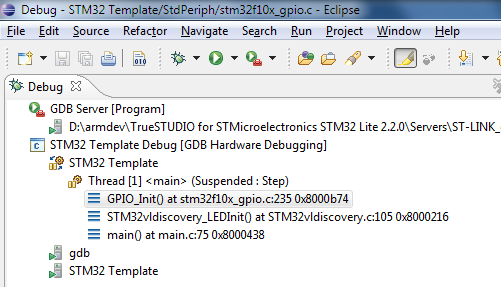
The built-in ST-Link on the ST Discovery board also supports live debugging of the program running on the Cortex M3. If you’re coming from the Arduino, or vanilla AVR development with an AVRISP mkII programmer that lacks debugging capability, this is a quantum leap forward. The people who wrote the Eclipse + Code Sourcery + STM32 setup guide also wrote an excellent hardware debugging setup guide, so I won’t repeat the steps here. Unfortunately, it involves downloading the entire Atollic Lite toolchain (250MB) just to get the ST-Link compatible gdbserver it contains. This also requires registering with Atollic, and getting a (free) activation key. It’s a hassle, but you only need to do it once.
Debugging works just how you’d expect. You can step through running code, set breakpoints, examine variable values, and view the call stack. Stepping through code seems unexpectedly slow, taking 1-2 seconds to step over a single line. The gdbserver also crashed a few times while I was debugging, and the only clue was that attempts to start a new debugging session failed with a generic error. I also found that stepping over a line that branches to itself, like
for(; nCount != 0; nCount--);
put the debugger into a state where the program was suspended, but the debugger thought it was running, forcing me to press the “pause” button to regain control. The overall debugging experience was a bit rough around the edges, but was much better than nothing. A different toolchain might have provided a smoother debugging experience, and I don’t fault the Cortex M3 or the ST Discovery board hardware for the debugging problems I encountered.
Beyond the Examples
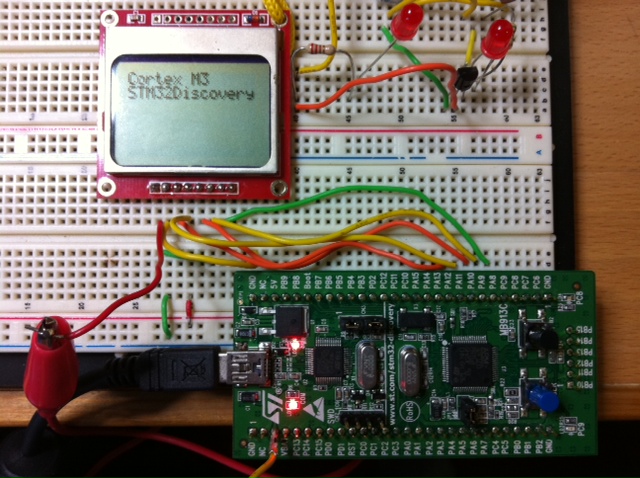
Running through the examples is a good way to get familiar with the Cortex M3, but to really learn what it’s like to develop for, there’s nothing better than creating your own custom project. Using the LED blink program as a template, I was able to port some code for controlling a Nokia 5110 LCD display, and print the message shown in the photo. The LEDs, transistor, and resistor in the upper right are from an unrelated circuit on my breadboard, and the only connections between the Discovery board and the LCD are the seven wires at the bottom.
My example program shows the code used to print the message on the LCD. There were no real surprises during development, and it only took me about 30 minutes to get the LCD working with the ST Discovery board. The only oddity I encountered was that there doesn’t appear to be a calibrated wait/delay function anywhere in the STM32 libraries. I wrote my own delay_ms() function that’s roughly accurate, assuming a 24 MHz clock and code compiled in the Debug configuration. It’s an imperfect solution, so if there’s not already a suitable delay function somewhere in another ARM library, it will probably be necessary to use a timer to get delays independent of clock speed and compiler options.
The GPIO_ library is great for getting projects up and running quickly. For high-speed performance-sensitive designs, however, there may be an unacceptable amount of overhead involved in calling a library function every time an I/O pin needs to be manipulated. In practice, the compiler may inline these functions when building Release configuration code, but I didn’t investigate to confirm it.
When powered by USB, the voltage at the ST Discovery board’s 3V3 pin is only about 2.97V, with no load. That might cause problems for some devices, but the Nokia 5110 LCD worked fine at that voltage.
Conclusions
Are the Cortex M3 and STM32 Discovery board what you’ve been looking for? In what kinds of projects do they fit best?
As an alternative to an Arduino or vanilla AVR board, the STM32 Discovery board looks like a clear winner in terms of price and hardware. It has more I/Os, more peripherals, larger memories, faster core clock MHz speed, and more performance per MHz due to its 32-bit internal design. All that, and it’s priced at less than half the cost of an Arduino.
What the STM32 Discovery lacks is easy-to-use development tools, and a large community of other users to collaborate with. The method I used to create a toolchain is probably too complex for many beginners, and they won’t be able to afford the commercial alternatives, so they’ll likely be shut out of Cortex M3 development entirely. Even if they do get the toolchain installed successfully, they won’t find the wealth of examples, 3rd-party libraries, or other support materials that exist in the AVR world. The value of that support shouldn’t be underestimated. Performance and memory aren’t everything.
The STM32 Discovery board is better matched for experienced microcontroller developers who’ve already done some work outside the Arduino environment, and are ready to accept additional complexity in exchange for major hardware improvements. The 24 MHz 32-bit Cortex M3 on the STM32 Discovery board is already a nice step up from 8-bit AVRs, but it’s just the beginning of the Cortex M3 line. Higher-end members of the Cortex M3 family can perform complex real-time tasks not possible on an AVR, drive high resolution color displays, run a real-time micro-OS capable of scheduling many programs at once, or even run Linux. For those who need this kind of power, the Cortex M3 is a great choice.
Read 10 comments and join the conversation10 Comments so far
Leave a reply. For customer support issues, please use the Customer Support link instead of writing comments.
Thanks for sharing this nice introduction to STM32 and Cortex M3. I was considering getting one but setting up the tool chain seems more trouble than it is worth. I think Microchip PIC32 could also be a contender in your mini comparison table. Digilent has these ChipKIT cards with PIC32 on them starting at $26. Not bad for 16KB SRAM and a 80 Mhz clock. They are Arduino compatible (which I do not care personally but might be useful for folks switching over from plain Arduino’s).
Cheers.
[…] good list of the various toolchains and utilities for the STM32 Programming STM32F10x I/O port pins Cortex M3 For Dummies – STM32 Discovery Board LD_AddCustomAttr("AdOpt", "1"); LD_AddCustomAttr("Origin", "other"); […]
The discovery board is great. I ve been working on it for a month now, and I have nothing but nice things to say about it. About the development tool. I downloaded the Atollic TrueSTUDIO free version. It runs great and the guys from ST and also Atollic made a lot of effort to make things easier for the newbies. There are also a lot of code examples wich makes the learning stress free. It is a powerfull and cheap board and I have a feeling that it is destined for success.
I apologize for possible spelling mistakes.
Thank you for this example..can you explain us more the connections between the Discovery board and the LCD (like this : PA8 –> pin1 of LCD, PA9 –> pin…). Thank you :))
Sorry, I tore down that circuit and no longer have the exact pin mappings. You should be able to determine it from the STM32 manual, though. The signal names used in my code are the same as those silkscreened on the LCD module for each pin.
Can we replace 24MHz crystal with the existing crystal
Great web page, thanks,
Users of STM32 Discovery boards (or any ARM processors) might want to look at the CooCox IDE. Free, lots of examples, and supports hundreds of ARM processors from 9 manufacturers. I just got it working on a project that I could no longer compile on Atollic since they reduced their max code size to 32K. Very nice.
Dave Erickson
I recently bought 200 NXP cortex m3 processors, i would like to sell 100 of them, if anyone would like to purchase them i’ll definitely give a great deal, less than what 100 would cost wholesale.. i can be reached at 6478025150 or andrew@gelmedia.net
or if anyone would have any suggestions of where i should post or who may be interested in these please let me know, thanks
kind regards
Andrew
Steve, how or why did you select ATMEGA132P for your Mini Backwoods logger? What were you choices and why you did not consider PIC16F or PIC18F families?
Backwoods Logger used the Atmega 328P, because I was already familiar with it from Arduino usage and other projects. I’ve never tried a PIC.