

Archive for January, 2012
Mouse Freeze Debugging

Last October, Plus Too first booted successfully into the Macintosh Finder. Ever since then, it’s exhibited an intermittent mouse freezing bug. The FPGA Mac replica runs normally for a few minutes, during which the mouse works normally, and it’s possible to exercise menus, run programs, and do everything else you’d expect from a working Mac. But somewhere after a minute or two of activity, the mouse pointer invariably freezes in one spot, and the computer seems to halt. The bug appears to be related to mouse movements, and faster, more frequent mouse movements cause the problem to appear sooner. If the mouse remains unmoved, then Plus Too will happily run for hours without problems.
In October I was already tired from the work needed to get Plus Too to that point, and had no desire to chase the mouse freeze problem further at that time. The project sat idle while I turned my attention to other things, and saw now further progress until this week. That’s when I decided it was finally time to track down the cause of the mouse freeze bug.
Mouse Interrupts
Macintosh mouse handling requires two different interrupts in order to work correctly. When the user moves the mouse, the SCC triggers a level 2 CPU interrupt to read the new position data. The interrupt handler adjusts a low memory global variable called MTemp to set the new on-screen mouse pointer position. Then every 1/60th of a second during the VBLANK interval (video retrace), the VIA triggers a level 1 CPU interrupt. The VBLANK interrupt handler erases the on-screen mouse pointer from its old position, and redraws it at the new position indicated by MTemp.
When the Plus Too mouse froze, I found that the level 2 SCC interrupt was still getting called normally, and MTemp was being adjusted correctly. However, the level 1 cursor VBL task was not getting called, so the mouse pointer was never redrawn at the new position. Further investigation showed that no other VBL tasks were getting called either. In fact, no level 1 VIA interrupts of any type were being processed. At first I thought this might be a problem with the Verilog code that implements my VIA replica, but I found that the VIA was still asserting its IRQ line, but the CPU was just ignoring it. Why?
According to the CPU status register, when a mouse freeze occurs, the CPU is permanently stuck with its current interrupt priority level at 1, instead of its normal value of 0. Because interrupts equal to or below the current IPL will be ignored, no VIA interrupts are ever processed, so the mouse VBL task never gets called. Level 2 SCC interrupts can still pre-empt the CPU, so MTemp gets updated correctly, but when the level 2 interrupt handler completes it returns to whatever the CPU was previously doing at level 1.
Stuck at Interrupt Priority Level 1
So how might the CPU get stuck at IPL 1? How does it get to IPL 1 in the first place? The normal way IPL 1 is reached is during a level 1 VIA interrupt handler, when the CPU sets the IPL automatically. These handlers normally do some processing and then return, which automatically restores the IPL to 0. This means one way the CPU could get stuck at IPL 1 would be if a level 1 interrupt handler went into an infinite loop and never returned. Looking at the level 1 interrupt handlers in the Mac Plus ROM, there are:
- One Second timer – From inspecting the code, this is a trivial handler, and will always return.
- VBLANK – This handler explicitly sets the IPL back to 0, so it can be pre-empted by other level 1 interrupts.
- Timer 1 and keyboard – I haven’t implemented these interrupts in the VIA yet, so they can never occur.
- Timer 2 – This is the only VIA interrupt yet implemented whose ROM handler might conceivably fail to return.
- System handlers – After booting the Mac, the system software might install new VIA interrupt handlers or patch the ones in ROM, creating additional opportunities for handlers that don’t return. Unfortunately I have no good way to test that further.
In addition to a non-returning level 1 interrupt handler, the other way the CPU could get stuck at IPL 1 is if some code explicitly sets the IPL to 1. From looking at a disassembly of the ROM code, several routines definitely do this when modifying global lists: VInstall, PostEvent, OSEventAvail, FlushEvents. The Sony floppy driver also explicitly sets the IPL to 1 in at least two cases. There are also many examples in the ROM code where the IPL is set using a value passed in a register or on the stack, where I can’t say for certain what value it’s being set to. And as before, the system software loaded from disk might contain additional code that directly manipulates the IPL, which I wouldn’t see in the ROM disassembly.
The best way to determine what’s happening would be to wait until the mouse freezes, then pause the CPU when it’s stuck at IPL 1, and look at what code it’s executing. I’ve attempted to do just that, but I lack good tools for software debugging (as opposed to debugging the Verilog hardware model), and I haven’t been able to learn anything very useful. Whenever I interrupt the CPU, it’s either executing some system code in RAM that was loaded from disk, or some fairly innocuous piece of ROM code like the trap dispatcher. I’ve been able to determine any higher level purpose to the code that suggests what it’s trying to do or why it never exits IPL 1.
Finding a Fix
One path might be to add MacsBug to my system disk image, then invoke it when the mouse freeze occurrs, and examine the stack trace and disassembly in an attempt to learn more. MacsBug requires the use of a keyboard, though, and I haven’t yet implemented the keyboard hardware. Even if the keyboard worked, I’m reluctant to start into debugging random pieces of system software that I know nothing about, but maybe that’s unavoidable.
Another possibility is to determine what was the most recent time the IPL was changed from 0 to 1. That might not be enough information to solve the problem, but it would be a start. I might be able to find that info using Altera’s Signal Tap logic analyzer, or maybe I could modify the Verilog machine model to keep track of the IPL changes for me.
My hunch is that some piece of code is going into an infinite loop while trying to access a piece of hardware I haven’t yet implemented, like VIA timer 1, the keyboard, serial port, sound hardware, or PRAM. If all else fails, I could just keep adding more hardware to my Verilog model, and see if the mouse freeze problem disappears at some point. One intriguing clue is that the mouse problem is much more difficult to reproduce when the General control panel is in the foreground. This control panel sets the date and time, sound volume, and other settings that are stored in PRAM. With PRAM not yet implemented, the control panel behaves oddly, and the system time never advances beyond 12:00:00 AM. Perhaps the General control panel is constantly attempting to read or write PRAM, which somehow affects the likelihood of the mouse freeze bug occurring? It’s little more than a wild guess, but PRAM is as good a place as any to start implementing more hardware.
One thing I can’t explain is why frequent rapid mouse movements appear to cause the freeze problem, since my investigations suggest the frozen mouse pointer is merely a symptom of VIA interrupts not getting processed, rather than a cause of anything. Since mouse movements generate a level 2 SCC interrupt, maybe there’s a bug in my design that occurs when a level 2 interrupt pre-empts a level 1 interrupt under certain conditions, or when both interrupts are triggered at the same time. There are some bugs in my mouse implementation as well, which appear to cause a backlog of mouse updates under some situations. I’d assumed these were unrelated to the freezing problem, but maybe I should try getting to the problem of that first. I wish I had a clearer idea of how to proceed, instead of just clutching at straws!
Read 8 comments and join the conversationPlus Too Interrupt Bug
Mark McDougall (tcdev) discovered what looks like a serious bug in the way Plus Too handles interrupts. It appears my design causes the 68000 CPU to use the wrong interrupt handler vector! How it could work at all under those circumstances isn’t clear, since I would expect it to crash the moment an interrupt is first triggered, but I fixed the bug anyway. I had hoped it would eliminate the mysterious freeze-ups I’ve been getting with Plus Too after a few minutes of active mouse movements in the Finder, but sadly it didn’t appear to make any difference.
Vectored Interrupts
Here’s what’s happening. Plus Too (and the Macintosh it replicates) use vectored interrupts. When an interrupt is triggered, the 68000 responds with an interrupt acknowledge cycle. It sets the 24-bit address bus to all 1’s, except for A3-A1, which are set to the level of the interrupt being acknowledged. There is no A0 output from the CPU, since it uses upper/lower byte strobes instead. So to acknowledge a level 1 interrupt (the VIA), the CPU would set the address bus to:
1111 1111 1111 1111 1111 001x
with X being the invisible A0 bit. The memory interface (in this case, my Plus Too design) is supposed to respond by placing an interrupt vector number on the 16-bit data bus. The CPU then multiplies the vector number by 4 internally, in order to get the memory address of the interrupt vector. It then uses that vector to find the location of the interrupt handler routine to execute.
In the case of the Macintosh, the external interrupt handlers begin with vector number $18, which when multiplied by 4 is the vector found at memory address $60. The level 1 VIA interrupt vector is number $19 found at $64, and so on. So to select the proper vector, the memory interface should respond to interrupt acknowledge cycles with $18 + the interrupt level.
A Missing Bit
That’s what I intended to do, but somewhere during development, my Plus Too code lost an address bit. The relevant piece of Verilog code looked something like:
input [1:0] addrLo; // A2-A1
output [15:0] dataOut;
...
assign dataOut = { 13'h3, addrLo }; // use A3-A1 to construct an interrupt number offset from $18
Oops. That code doesn’t do what the comment says. It ignores A3, meaning that interrupt levels 4-7 will never be handled properly. These correspond to the programmer’s debug switch on the Mac. Worse, it generates interrupt numbers that are offset from $C, not $18. So for interrupt level 1 (the VIA), it will generate a response of interrupt number $D, which is at memory address $38.
According to my docs, $38 is an unassigned/reserved vector. In fact, all the vectors from $30 to $5C are reserved or unassigned. So how does that work at all? Why doesn’t it crash the moment a VIA interrupt is first triggered? Is it possible that the reserved vector entry just happens to contain the right value somehow? That seems very unlikely.
Fixed?
The fix is pretty simple: addrLo should be three bits instead of two, and contain A3-A1. I made this change, and Plus Too behaves no differently than before as far as I can tell. It still kind of mostly works, but exhibits frequent freeze-ups after a few minutes of use, that seem to be related to mouse movements somehow. Maybe the two problems are totally unrelated, but I’d hoped the interrupt vector problem might explain the freeze-ups.
I still can’t explain how Plus Too ever worked before, with external interrupt numbers given the wrong offset.
Read 6 comments and join the conversationReady to Assemble
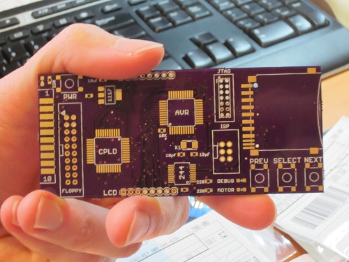
It took longer than I’d expected, but all the parts needed to build three Floppy Emus have finally arrived! That’s three custom-made circuit boards from Dorkbot PDX, plus the SD card sockets, CPLDs, AVRs, and a whole pile of buttons, LEDs, and other components. Now it needs some soldering love.
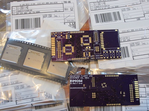
The boards from Dorkbot are as high-quality as ever: well-centered drills, crisp silkscreen, gold-plated pads, proper via tenting, and everything else. Unfortunately my last few Dorkbot PCB orders have been slower than normal to arrive. Even when I submit my design on the night before the deadline, the total end-to-end time from submission to boards in my mailbox is no faster than from a Chinese PCB maker delivering via China post. It’s about 17 calendar days in either case. With manufacturing done in the USA, one of Dorkbot’s big advantages is supposed to be turn-around time, but in practice it’s more a question of a higher price for a higher quality board than any question of time. I don’t mean to harp on Dorkbot– the guy who runs the PCB order is very nice, and I’m pretty sure he sinks a ton of his time into it while earning almost zero profit. I only wish it could be a little faster.
Now for the bad news: my enthusiasm for putting this board together seems to have evaporated. My hobby efforts come in waves, and I was very busy on this project in November and December, but now I can’t quite get excited about it. It’s not simply a question of soldering on the parts– I also need to modify the AVR firmware to use the ATMEGA1284 instead of the ‘328 from the prototype, implement indirect CPLD programming, and then implement the write buffering mechanism I keep talking about. I’m sure I’ll get to it soon enough, but right now when I look at the bare board, my mind wants to go read a book or go for a hike rather than jump into assembly. I’ve learned to listen to those voices, else a hobby can turn into a chore and cease to be any fun.
Read 8 comments and join the conversation
Parts Order By Mail

Today I ordered the parts needed to build three Floppy Emu boards, the Macintosh floppy disk drive emulator. Everything should be here by next week, so I can start building! In these small quantities, the total cost for the parts is about $47 per board, which is a lot more than I’d hoped. If I ever sell assembled Floppy Emus, they’ll probably need to have a retail price over $100 to cover the cost of assembly, testing, packaging, and a small profit to make it worth the time required.
In addition to being a “real” device instead of a hand-wired breadboard prototype, the new board will also use different parts than the original. The biggest change is the switch to an ATMEGA1284P AVR microcontroller, which has 16K of internal RAM to allow experimentation with different write buffering strategies. The CPLD is different too, with a Xilinx XC9572XL replacing the Altera-powered module that I scavenged from Tiny CPU for prototyping use.
Although the board has a footprint for a Xilinx JTAG header, I didn’t actually order the header, nor do I own a Xilinx JTAG programmer. I’m counting on programming the CPLD indirectly via the microcontroller, using the method described in Xilinx app note 058. If I can’t get that to work, I’ll have to go back and buy the header and a Xilinx programmer, which will mean more delays and more money. I’m keeping my fingers crossed that the indirect programming method turns out OK.
Read 12 comments and join the conversation