

Archive for the 'Plus Too' Category
Plus Too Mac Replica, New Progress!
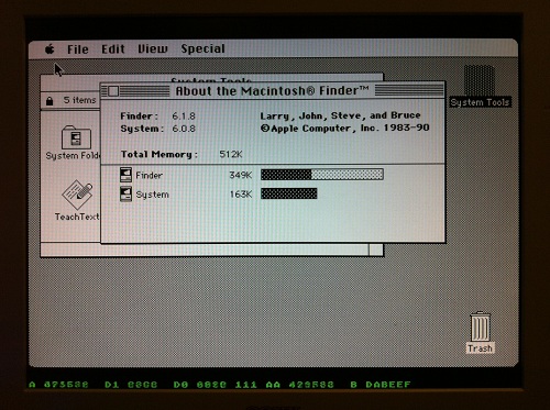
After a long hiatus, there’s new progress for the Plus Too FPGA-based Macintosh replica. Till Harbaum has ported my original, unfinished design to the MiST board, and has begun making fixes and improvements. The video shows Plus Too booting on the MiST board, and selecting a boot floppy disk image from the MiST’s overlay menu.
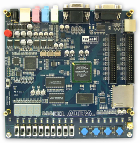
Plus Too is a reimplementation of a Macintosh Plus, synthesized in an FPGA. All of the original Mac’s chips are modeled in a hardware description language and implemented in the FPGA’s logic cells: the 68000 CPU, VIA, SCC, IWM, memory controller, video circuitry, etc. I did the original work four years ago using an Altera DE1 evaluation board, which pairs an FPGA with some SRAM, flash memory, and other components. It worked well enough to boot Mac System 6.0.8 from a replica floppy disk, but it suffered from stability problems, and had no support for keyboard, sound, SCSI, serial ports, or real-time clock.
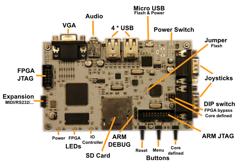
Till Harbaum designed the MiST board to implement classic 16-bit computers like the Amiga and Atari ST as a System-on-a-Chip using modern hardware, and it’s better suited to the task of replication than a generic board like the DE1. It combines a powerful Altera FPGA with a separate ARM-based CPU. The ARM CPU isn’t used directly in the replicated system, but performs helper functions like loading the selected FPGA core from the SD card, managing configuration overlay menus, and mimicking external peripherals like disks. MiST already has working cores for the Amiga and Atari ST, as well as a large number of 8-bit computers and game consoles. The classic Mac is the only computer from that era that’s still missing.
Till’s progress with Plus Too on MiST so far:
- ported the original design to the MiST
- adapted the memory controller to use SDRAM instead of SRAM
- updated the 68000 CPU model
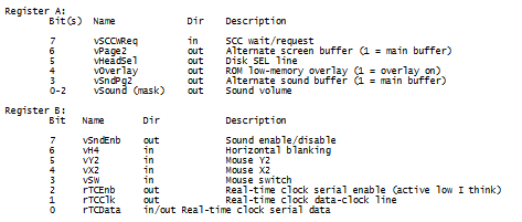
- replaced the 6522 VIA implementation with one from the BBC Micro
- implemented keyboard support
- added an on-screen menu to select floppy disk images
- fixed assorted timing bugs
Somewhere along the way, the stability problems I observed with the DE1 version also disappeared. This might be a hardware difference, or something related to the timing problems that were fixed.
Till is currently working on implementing on-the-fly GCR encoding of standard Macintosh disk images, similar to the way Floppy Emu works. The original Plus Too required disk images to be GCR encoded ahead of time, using a separate utility program.
His roadmap after that includes:
- get both floppies to work nicely with .dsk images (read only)
- make the video timing closer to a real Mac
- add sound
Additional info on the MiST board is at http://code.google.com/p/mist-board/
Source code for Mac-MiST is at https://github.com/mist-devel/mist-board/tree/master/cores/plus_too
Binaries are at https://github.com/mist-devel/mist-binaries/tree/master/cores/plus_too
Some discussion about the Mac core for MiST is at http://atari-forum.com/viewtopic.php?f=101&t=28648
Additional German-language discussion is at http://mist-fpga.net/viewtopic.php?f=24&t=102
Plus Too Files
Since the Plus Too project hasn’t seen any progress in a year, I’m posting all the design files in the hopes that someone else may want to build on what I’ve done. If you missed the earlier discussions about it, Plus Too is a working replica of a Macintosh Plus, implemented in an FPGA.
Download the Plus Too file archive
What You’ll Need
- An Altera DE1 FPGA development board
- A Windows-based PC
- An old PS/2 mouse from a PC (newer USB-based mice won’t work)
- A VGA monitor capable of displaying 1024 x 768 @ 60Hz
Setup Instructions
- Download the Control Panel configuration file DE1_USB_API.sof into the FPGA. This file is included on the CD that comes with the DE1 kit. See sections 3.1 and 4.1 of the DE1 user manual for help.
- Run the DE1_Control_Panel.exe program on your PC. This is also included on the DE1 CD.
- Click on the Flash tab.
- Click the Chip Erase button to clear the DE1 Flash memory.
- In the Sequential Write section, enter 0 for the address and click the File Length checkbox.
- Click the Write a File to Flash button. When prompted, select the plusrom.bin file from the Plus Too archive, and write the file to the DE1 memory. This is a ROM dump from Macintosh Plus.
- In the Sequential Write section, enter 20000 (hex) for the address. Confirm the File Length checkbox is still checked.
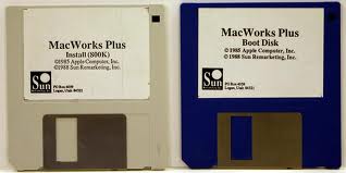
- Click the Write a File to Flash button. When prompted, select the Disk608-800K.bin file from the Plus Too archive, and write the file to the DE1 memory. This is a System 6.0.8 boot disk image.
- Download the Plus Too configuration file plusToo_top.sof into the FPGA. This is included in the Plus Too archive.
You should now be up and running! Connect a PS/2 mouse and a VGA monitor for some retro-computing fun.
Using Plus Too
There’s no support for the keyboard, sound, or SCSI. The floppy disk is read-only.
Watch out! There’s a bug somewhere that causes PlusToo to crash or the mouse to stop working (not sure which) if you move the mouse around too much or too fast. I’m still not sure what the cause is, but I wrote about it more in a previous post.
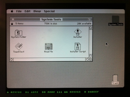
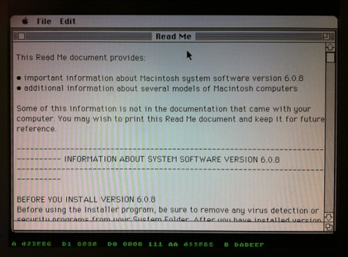
Along the bottom of the screen you’ll see some debug information, shown in green text. From left to right, these are:
- A – the current value on the address bus
- D1 – the incoming value from the data bus
- D0 – the outgoing value from the data bus
- (not labeled) – the current interrupt level
- AA – the previous value of the address bus
- B – the breakpoint address
You can set the breakpoint address using the DE1 switches. When the current address equals the breakpoint address, Plus Too will halt.
The hardware can be controlled using the four push-button switches on the DE1 board, which are labeled Key0 through Key3, as well as the 10 slide switches labeled SW0 through SW9.
- Key2 inserts a blank disk into the external drive. Useful for debugging only.
- Key1 inserts the System 6.0.8 disk into the internal drive.
- Key0+Key1 together perform a reset.
- SW0 selects between free-running (switch down) and single-step mode (switch up).
- When in single-step mode:
- Key0 performs a step
- Key1, Key2, and Key3 load the low, middle, and high bytes of the breakpoint address from switches SW9-SW2.
Making Floppy Disk Images
The Disk608-800.bin file is not a standard floppy disk image file such as you would use with a Mac emulator like Mini vMac or Basilisk II. It’s an encoded file containing data exactly as it would appear on a real floppy disk, complete with sector markers, checksums, and inter-sector timing gaps.
If you want to take an 800K floppy image from your favorite emulator and use it with Plus Too, you’ll need to encode it using my Floppy Encoder utility. It takes a normal floppy image file as input, which usually has a .dsk filename extension, and generates an encoded image file with a .bin extension. The resulting .bin file can then be substituted in step 8 of the setup instructions to run Plus Too with the new floppy image.
Extending Plus Too
The Verilog source files are included in the file archive, for anyone who wants to try taking the project further. The biggest thing it needs now is for someone to set up proper timing constraints. I played around with it a bit, but I didn’t really understand the constraint editor and was eager to move on. PlusToo mostly works without specifying any constraints, but sometimes it will randomly fail to boot up, or exhibit bizarre video bugs. I’ve found that changing the number of signals and sample depth of the Signal Tap logic analyzer setup can fairly predictably make such problems appear and disappear.
The constraints should be:
- External 50 MHz clock
- Internal 32.5 MHz clock synthesized with a PLL. This is the video clock, called clk32 in the Verilog source.
- Internal 8.125 MHz clock named clk8, derived from clk32 with a clock divider. (I couldn’t make this work with a PLL)
- Flash ROM has an address-to-data delay of 70ns. The total delay from clk8 to when all the Flash control and address lines are stable, plus 70 ns, plus whatever the setup time is for the FPGA registers that will receive the Flash data (how do you determine this?), must be less than the clock period of 123ns.
- Similarly for the SRAM, except I believe its address-to-data delay is 10ns (check datasheet). The SRAM should also have additional constraints for write timing.
Read 23 comments and join the conversation
Mouse Freeze Debugging

Last October, Plus Too first booted successfully into the Macintosh Finder. Ever since then, it’s exhibited an intermittent mouse freezing bug. The FPGA Mac replica runs normally for a few minutes, during which the mouse works normally, and it’s possible to exercise menus, run programs, and do everything else you’d expect from a working Mac. But somewhere after a minute or two of activity, the mouse pointer invariably freezes in one spot, and the computer seems to halt. The bug appears to be related to mouse movements, and faster, more frequent mouse movements cause the problem to appear sooner. If the mouse remains unmoved, then Plus Too will happily run for hours without problems.
In October I was already tired from the work needed to get Plus Too to that point, and had no desire to chase the mouse freeze problem further at that time. The project sat idle while I turned my attention to other things, and saw now further progress until this week. That’s when I decided it was finally time to track down the cause of the mouse freeze bug.
Mouse Interrupts
Macintosh mouse handling requires two different interrupts in order to work correctly. When the user moves the mouse, the SCC triggers a level 2 CPU interrupt to read the new position data. The interrupt handler adjusts a low memory global variable called MTemp to set the new on-screen mouse pointer position. Then every 1/60th of a second during the VBLANK interval (video retrace), the VIA triggers a level 1 CPU interrupt. The VBLANK interrupt handler erases the on-screen mouse pointer from its old position, and redraws it at the new position indicated by MTemp.
When the Plus Too mouse froze, I found that the level 2 SCC interrupt was still getting called normally, and MTemp was being adjusted correctly. However, the level 1 cursor VBL task was not getting called, so the mouse pointer was never redrawn at the new position. Further investigation showed that no other VBL tasks were getting called either. In fact, no level 1 VIA interrupts of any type were being processed. At first I thought this might be a problem with the Verilog code that implements my VIA replica, but I found that the VIA was still asserting its IRQ line, but the CPU was just ignoring it. Why?
According to the CPU status register, when a mouse freeze occurs, the CPU is permanently stuck with its current interrupt priority level at 1, instead of its normal value of 0. Because interrupts equal to or below the current IPL will be ignored, no VIA interrupts are ever processed, so the mouse VBL task never gets called. Level 2 SCC interrupts can still pre-empt the CPU, so MTemp gets updated correctly, but when the level 2 interrupt handler completes it returns to whatever the CPU was previously doing at level 1.
Stuck at Interrupt Priority Level 1
So how might the CPU get stuck at IPL 1? How does it get to IPL 1 in the first place? The normal way IPL 1 is reached is during a level 1 VIA interrupt handler, when the CPU sets the IPL automatically. These handlers normally do some processing and then return, which automatically restores the IPL to 0. This means one way the CPU could get stuck at IPL 1 would be if a level 1 interrupt handler went into an infinite loop and never returned. Looking at the level 1 interrupt handlers in the Mac Plus ROM, there are:
- One Second timer – From inspecting the code, this is a trivial handler, and will always return.
- VBLANK – This handler explicitly sets the IPL back to 0, so it can be pre-empted by other level 1 interrupts.
- Timer 1 and keyboard – I haven’t implemented these interrupts in the VIA yet, so they can never occur.
- Timer 2 – This is the only VIA interrupt yet implemented whose ROM handler might conceivably fail to return.
- System handlers – After booting the Mac, the system software might install new VIA interrupt handlers or patch the ones in ROM, creating additional opportunities for handlers that don’t return. Unfortunately I have no good way to test that further.
In addition to a non-returning level 1 interrupt handler, the other way the CPU could get stuck at IPL 1 is if some code explicitly sets the IPL to 1. From looking at a disassembly of the ROM code, several routines definitely do this when modifying global lists: VInstall, PostEvent, OSEventAvail, FlushEvents. The Sony floppy driver also explicitly sets the IPL to 1 in at least two cases. There are also many examples in the ROM code where the IPL is set using a value passed in a register or on the stack, where I can’t say for certain what value it’s being set to. And as before, the system software loaded from disk might contain additional code that directly manipulates the IPL, which I wouldn’t see in the ROM disassembly.
The best way to determine what’s happening would be to wait until the mouse freezes, then pause the CPU when it’s stuck at IPL 1, and look at what code it’s executing. I’ve attempted to do just that, but I lack good tools for software debugging (as opposed to debugging the Verilog hardware model), and I haven’t been able to learn anything very useful. Whenever I interrupt the CPU, it’s either executing some system code in RAM that was loaded from disk, or some fairly innocuous piece of ROM code like the trap dispatcher. I’ve been able to determine any higher level purpose to the code that suggests what it’s trying to do or why it never exits IPL 1.
Finding a Fix
One path might be to add MacsBug to my system disk image, then invoke it when the mouse freeze occurrs, and examine the stack trace and disassembly in an attempt to learn more. MacsBug requires the use of a keyboard, though, and I haven’t yet implemented the keyboard hardware. Even if the keyboard worked, I’m reluctant to start into debugging random pieces of system software that I know nothing about, but maybe that’s unavoidable.
Another possibility is to determine what was the most recent time the IPL was changed from 0 to 1. That might not be enough information to solve the problem, but it would be a start. I might be able to find that info using Altera’s Signal Tap logic analyzer, or maybe I could modify the Verilog machine model to keep track of the IPL changes for me.
My hunch is that some piece of code is going into an infinite loop while trying to access a piece of hardware I haven’t yet implemented, like VIA timer 1, the keyboard, serial port, sound hardware, or PRAM. If all else fails, I could just keep adding more hardware to my Verilog model, and see if the mouse freeze problem disappears at some point. One intriguing clue is that the mouse problem is much more difficult to reproduce when the General control panel is in the foreground. This control panel sets the date and time, sound volume, and other settings that are stored in PRAM. With PRAM not yet implemented, the control panel behaves oddly, and the system time never advances beyond 12:00:00 AM. Perhaps the General control panel is constantly attempting to read or write PRAM, which somehow affects the likelihood of the mouse freeze bug occurring? It’s little more than a wild guess, but PRAM is as good a place as any to start implementing more hardware.
One thing I can’t explain is why frequent rapid mouse movements appear to cause the freeze problem, since my investigations suggest the frozen mouse pointer is merely a symptom of VIA interrupts not getting processed, rather than a cause of anything. Since mouse movements generate a level 2 SCC interrupt, maybe there’s a bug in my design that occurs when a level 2 interrupt pre-empts a level 1 interrupt under certain conditions, or when both interrupts are triggered at the same time. There are some bugs in my mouse implementation as well, which appear to cause a backlog of mouse updates under some situations. I’d assumed these were unrelated to the freezing problem, but maybe I should try getting to the problem of that first. I wish I had a clearer idea of how to proceed, instead of just clutching at straws!
Read 8 comments and join the conversationPlus Too Interrupt Bug
Mark McDougall (tcdev) discovered what looks like a serious bug in the way Plus Too handles interrupts. It appears my design causes the 68000 CPU to use the wrong interrupt handler vector! How it could work at all under those circumstances isn’t clear, since I would expect it to crash the moment an interrupt is first triggered, but I fixed the bug anyway. I had hoped it would eliminate the mysterious freeze-ups I’ve been getting with Plus Too after a few minutes of active mouse movements in the Finder, but sadly it didn’t appear to make any difference.
Vectored Interrupts
Here’s what’s happening. Plus Too (and the Macintosh it replicates) use vectored interrupts. When an interrupt is triggered, the 68000 responds with an interrupt acknowledge cycle. It sets the 24-bit address bus to all 1’s, except for A3-A1, which are set to the level of the interrupt being acknowledged. There is no A0 output from the CPU, since it uses upper/lower byte strobes instead. So to acknowledge a level 1 interrupt (the VIA), the CPU would set the address bus to:
1111 1111 1111 1111 1111 001x
with X being the invisible A0 bit. The memory interface (in this case, my Plus Too design) is supposed to respond by placing an interrupt vector number on the 16-bit data bus. The CPU then multiplies the vector number by 4 internally, in order to get the memory address of the interrupt vector. It then uses that vector to find the location of the interrupt handler routine to execute.
In the case of the Macintosh, the external interrupt handlers begin with vector number $18, which when multiplied by 4 is the vector found at memory address $60. The level 1 VIA interrupt vector is number $19 found at $64, and so on. So to select the proper vector, the memory interface should respond to interrupt acknowledge cycles with $18 + the interrupt level.
A Missing Bit
That’s what I intended to do, but somewhere during development, my Plus Too code lost an address bit. The relevant piece of Verilog code looked something like:
input [1:0] addrLo; // A2-A1
output [15:0] dataOut;
...
assign dataOut = { 13'h3, addrLo }; // use A3-A1 to construct an interrupt number offset from $18
Oops. That code doesn’t do what the comment says. It ignores A3, meaning that interrupt levels 4-7 will never be handled properly. These correspond to the programmer’s debug switch on the Mac. Worse, it generates interrupt numbers that are offset from $C, not $18. So for interrupt level 1 (the VIA), it will generate a response of interrupt number $D, which is at memory address $38.
According to my docs, $38 is an unassigned/reserved vector. In fact, all the vectors from $30 to $5C are reserved or unassigned. So how does that work at all? Why doesn’t it crash the moment a VIA interrupt is first triggered? Is it possible that the reserved vector entry just happens to contain the right value somehow? That seems very unlikely.
Fixed?
The fix is pretty simple: addrLo should be three bits instead of two, and contain A3-A1. I made this change, and Plus Too behaves no differently than before as far as I can tell. It still kind of mostly works, but exhibits frequent freeze-ups after a few minutes of use, that seem to be related to mouse movements somehow. Maybe the two problems are totally unrelated, but I’d hoped the interrupt vector problem might explain the freeze-ups.
I still can’t explain how Plus Too ever worked before, with external interrupt numbers given the wrong offset.
Read 6 comments and join the conversationA Working Hardware Replica of the Mac Plus
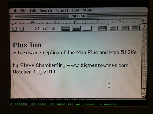
Plus Too is a home-made replica of a classic Macintosh computer using an FPGA. The project reached a major milestone yesterday, booting to the Finder for the first time, and running several programs. Since then I’ve been getting many inquiries, and because not everyone’s been following the project since its beginning, I’ve created a Plus Too project summary page to document the progress so far and my plans for the next version. If you’re new to Plus Too, please begin by reading the project summary page.
The screenshot above shows a Mac Write document opened with Plus Too. Because there’s no keyboard support yet, the document was created on another computer and added to the Plus Too boot disk image. Below the Macintosh screen region, hardware debugging information is displayed in green. This debug overlay is possible because a pixel-doubled 512 x 342 Mac image conveniently leaves some extra vertical space on a 1024 x 768 VGA display. From left to right, the debugging information shows the current state of the CPU address bus, data bus in, data bus out, address strobes, previous address, and breakpoint address. A poor-man’s breakpoint system is implemented by setting a breakpoint address with panel switches. When the address bus matches the breakpoint address, the CPU’s memory transfer acknowledge signal is withheld, effectively pausing the CPU.
The current system is implemented entirely with an unmodified Altera DE1 FPGA development board. The next version will use a custom-designed circuit board instead of the DE1 kit. The revised Plus Too will use a real 68000 CPU, and will add a microcontroller to manage the floppy disk SD card interface. It will also add the physical connectors necessary to use a real Mac Plus mouse and keyboard if desired.
What Works
The current system recreates a computer similar to a Mac 512Ke, with 512K of RAM and no SCSI. It boots from a System 6.0.8 floppy disk image stored in ROM. The disk image is pre-encoded into a series of virtual tracks and sectors, with the proper low-level layout, header, footer, checksum, and GCR disk byte format. This encoding is performed offline, using a custom-made utility program. Applications can be launched from the disk and run normally.
What Doesn’t Work
The disk is read-only, and there’s no keyboard, sound, SCSI, serial ports, real-time clock, or parameter RAM. The planned SD card interface for loading disk images hasn’t yet been built. There are some obvious stability problems, and the system tends to freeze up if the mouse is moved too rapidly. Disk I/O seems strangely slow– slower even than on a real Mac 512Ke or Mac Plus. There’s a long, long way to go before this project could be considered “done”, but it’s an exciting start!
Read 4 comments and join the conversationPlus Too – Hello World!
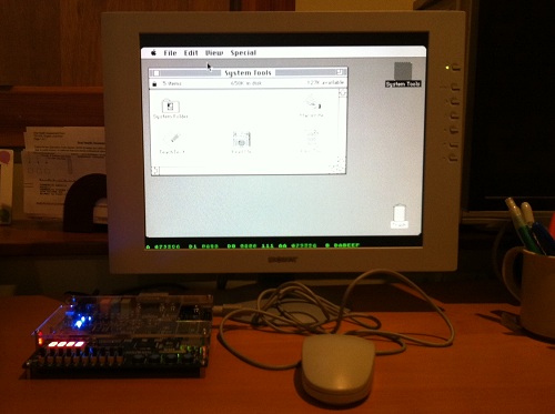
Plus Too works! Holy cow, it really works. Hot damn!
I didn’t want to tackle SD card loading yet, so the GCR-pre-encoded 800K disk image resides in ROM, just above the Macintosh ROM image. The floppy drive module uses the video module’s memory access time slot during hblank periods to load disk data, transparently to the CPU.
Plus Too ran for about five minutes while I took these photos, then it locked up. Not bad for the first boot.
Now, to celebrate with a cold beer!
Read 6 comments and join the conversation