Archive for the 'Bit Bucket' Category
Power Supply Design, Group Regulation, and Vintage Computers

Vintage computer power supplies will eventually grow old and die. Instead of rebuilding them, many people are opting to replace them with a PC-standard ATX power supply and a physical adapter to fit the vintage machine, similar to the ATX to Macintosh 10-pin adapters I recently discussed here. But this creates a potential problem that I hadn’t originally considered: group regulation of the output voltages causing some rails to go out of spec.
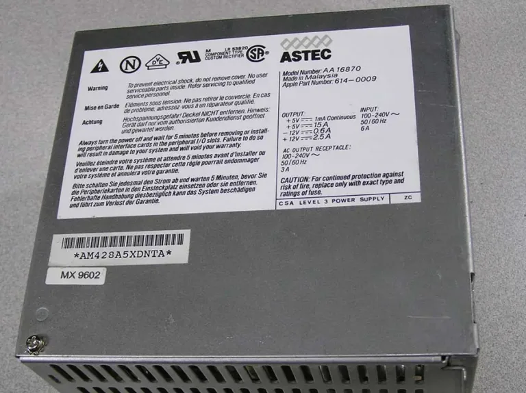
I’m trying to replace a Macintosh IIci/IIcx power supply, as shown in the photo above. With the help of a friend, I replaced it with this Logisys ATX PSU, and at first all seemed fine. But then I did some load tests in the Macintosh IIcx, adding more and more cards and peripherals while measuring the 5V and 12V supply regulation. The initial setup was a IIcx using the Logisys PSU, with 20MB RAM, no hard drives or floppy drives, no keyboard or mouse, no cards, and no ROM SIMM. I measured voltages at the empty hard drive power connector.

- initial readings: 4.932, 12.294
- +1 ethernet card, 1 ADB keyboard, 1 ADB trackball: 4.895, 12.302
- +1 Toby video card: 4.824, 12.327
- +1 Apple Hi-Resolution Display Card: 4.779, 12.340
- +2 BMOW Floppy Emus (internal and external): 4.763, 12.343
- +1 Zulu SCSI using term power: 4.742, 12.338
- +1 BMOW Wombat with attached USB hub, USB keyboard, USB mouse: 4.729, 12.343
- +1 12V fan rated 0.77W: 4.734, 12.325
Bolded values are out of spec. The additional load I was adding was all on the 5V supply, whose voltage kept sinking lower and lower while the mostly-unloaded 12V supply kept climbing higher. This is exactly what you’d expect from a PSU that uses group regulation, where all of the outputs are regulated using a single combined error feedback mechanism, instead of each output being independently regulated.
In the case of many common cheaper ATX PSUs, they are group regulated based on the combined error in the 5V and 12V outputs. In a severe cross-loading situation with lots of 5V load and minimal 12V load, the PSU is trying to split the difference by making 5V too low and 12V too high, which causes 5V to go out of spec. Adding a fan to create a small load on 12V helped a tiny bit. But extrapolating from that one fan, I’d need to add 41W of load on 12V to bring the 5V supply all the way up to where it should be.
The original stock PSU in the Macintosh IIcx and similar computers did not suffer this problem, and was presumably independently regulated. So what is the aspiring vintage computer PSU rebuilder to do here?
- Buy a much more expensive ATX PSU that is not group regulated, and that can supply enough amps on its 5V output (minimum 15A), and is small enough to fit the small physical dimensions inside the IIcx PSU enclosure. Finding options that tick all the boxes is difficult, and these may cost $100 or more. Most modern ATX PSUs can not supply enough current on their 5V output.
- Add a 12V dummy load using power resistors, something on the order of 10 to 40 Watts, to reduce the cross-loading between the 5V and 12V outputs. But what level of dummy load is correct? And what about the extra heat that will be generated?
- Design a custom PSU solution using a commercial 12V regulated supply plus a separate high-power buck converter for 5V, and another converter for -12V, and also something for 5V trickle and soft power like ATX’s PS_ON input.
- Something else clever that you may suggest.
Electric Bow Tie 3000 Reloaded

Ah, the Electric Bow Tie 3000: BMOW’s least-loved product. The bow tie was retired several years ago, but it’s still possible to make your own annoying neckwear device! I’ve belatedly uploaded the schematic, PCB files, parts list, and instructions here. For those who’ll be attending Mactoberfest Meetup this weekend, I’ll be giving away some Electric Bow Tie kits. These include the PCB, LEDs, and CdS photocell. The other parts (buzzer, 555 timer, etc) are available from DigiKey, Mouser, and other electronics suppliers.
Be the first to comment!ATX to Mac 10-pin Power Supply Adapter Kit

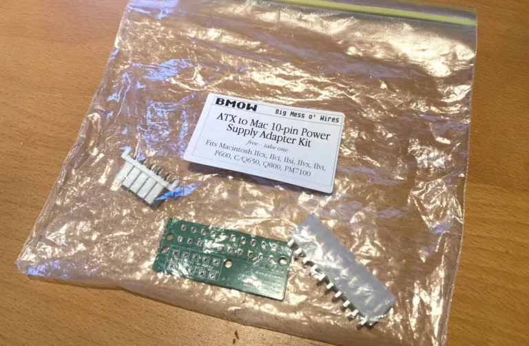
If you dabble with old computers, then you know the power supplies can fail just as often as the computers themselves. In the case of classic Macintosh computers, Apple didn’t use any kind of standard PSU, so buying new replacements isn’t possible. When a classic Mac PSU fails, the options are to recap and rebuild it, or make an adapter for another type of power supply. PC-style ATX supplies are cheap and readily available, and they offer the same +12V, +5V, -12V, and standby power outputs as Mac supplies. Wouldn’t an ATX-to-Mac PSU adapter be nice?
George Rudolf designed this simple ATX adapter and shared it on GitHub. It coverts a standard ATX 20-pin connector to the 10-pin connector found in the Macintosh IIcx, IIci, IIsi, IIvx, IIvi, Performa 600, Centris/Quadra 650, Quadra 800, and PowerMac 7100.


Aside from the different connectors, there’s also one small bit of active electronics on the adapter: an inverter for the ON signal. Classic Macs and PCs both support soft power, where the computer can be turned on from the keyboard or via software instead of with a hard on/off switch. This requires a power supply enable signal from a circuit using standby power, but the polarity of the ATX enable signal is the opposite of the Mac. Inverter to the rescue.
I was able to get 20 adapters assembled and shipped from JLCPCB for the princely sum of just $1.39 each. The connectors had to be sourced separately, but they’re readily available. Soldering the connectors only takes a few minutes, and they’re easy through-hole components.
I put together one of the 20 kits and installed it in my Macintosh IIci, and it worked great. I think it’s more useful for bench testing purposes than as a full PSU replacement, unless you want to go the extra mile of fashioning custom brackets to secure the ATX PSU inside the case.
For people who are attending Mactoberfest Meetup on October 14, I’ll have nineteen more of these ATX-to-Mac kits as free give-away items. You can assemble the kit right there at the meetup’s repair/work center. One of the Mactoberfest computer demos will also be a Mac IIci powered by an external ATX PSU, so you can see this adapter in action. I hope you enjoy these!

ImageWriter II Printer Resurrected
I’ve had an ImageWriter II printer gathering dust in the back of my closet for at least a decade. Originally purchased at the Silicon Valley Electronics Flea Market for 25 cents, it was an obsolete anachronism even then, and the seller was desperate to get rid of it. It came home with me, but I never used it and the printer was quickly forgotten.
Recently I wondered: Will it still work? Have the internal capacitors leaked their caustic innards all over the PCB? Has the ink ribbon from Bill Clinton’s presidency ossified into solid rock? Will those tiny and fantastic dot-matrix pins be stuck forever in tar-like goo?
Somewhat shockingly, I discovered that you can still buy new ImageWriter II ink ribbons in 2023. And also continuous feed paper, with the tractor holes on the sides. You can even find newly-made Mini DIN 8 printer cables, if you know where to look.
It was a journey back in time, straining to remember setup steps that I’d last done 30 years ago. In the classic Mac OS, where is printer setup done? In the vaguely-named Chooser desk accessory? Is it supposed to show me a list of installed printers? Do I need driver software? Which classic Mac OS programs even support printing?
After a few minutes of awkward experiments, I discovered TeachText and its six glorious built-in bitmap fonts, with a choice of six specific font sizes. No Postscript, vector fonts, or arbitrary text size scaling here.
I typed a few lines of text, clicked the print button, and… nothing. Seconds passed, and I felt the sting of failure, but then the printer sprang to life. Hooray, success! I was rewarded for my efforts with a soothing bzzzt-bzzzt-bzzzt symphony of print head movement as the ImageWriter slowly processed the page. And I do mean slowly. Even in normal quality mode, it takes about a minute to print a single page of text. I shudder to imagine the speed of high-quality print mode.
We are spoiled with today’s laser printers that can render a full page in seconds. For now it’s fun to relive the world of 1980s printing. I feel like I should be writing an 8th grade history report about Julius Caesar and then creating Happy Birthday banners with Print Shop.
For people who are attending Mactoberfest Meetup on October 14, I’ll have a computer running MacWrite and connected to this Imagewriter, so you can experience the good old days too. Bring your school history report on a 3.5 inch floppy.
Read 3 comments and join the conversationA Tale of Three Bidirectional Level Shifters
Level shifters, voltage translators: whatever you call them, these devices are very handy when interfacing 5V and 3.3V logic for devices that aren’t 5V-tolerant. The 74LVC244 has long been my go-to solution for unidirectional 5V to 3.3V level shifting, and for 3.3V to 5V I’ll typically do nothing, since the 5V inputs generally work OK without shifting. But sometimes you need bidirectional level shifting with automatic direction sensing, and you may also want to step up those 3.3V signals to a full 5V. Enter three solutions from Texas Instruments: TXB0104, TXS0104, and TXS0108. These three chips all provide 4 or 8 channels of bidirectional level shifting with auto direction sensing, and at first glance they all seem very similar. But as I recently discovered, under the hood you’ll find significant differences in how they work and the types of applications they’re best suited for.
TXB0104
TI describes this chip as a “4-Bit Bidirectional Voltage-Level Translator With Automatic Direction Sensing.”
This TXB0104 4-bit noninverting translator uses two separate configurable power-supply rails. The A port is designed to track VCCA. VCCA accepts any supply voltage from 1.2 V to 3.6 V. The B port is designed to track VCCB. VCCB accepts any supply voltage from 1.65 V to 5.5 V. This allows for universal low-voltage bidirectional translation between any of the 1.2-V, 1.5-V, 1.8-V, 2.5-V, 3.3-V, and 5-V voltage nodes. VCCA must not exceed VCCB.
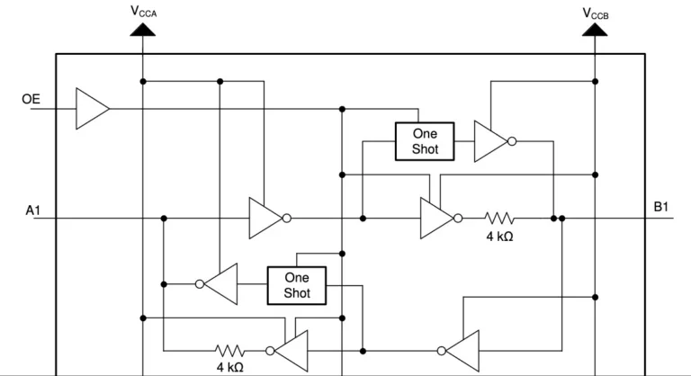
Power VCCA with 3.3V, power VCCB with 5V, and then it just works without any further configuration. Signals on pins A1..4 are propagated to pins B1..4 and vice-versa, while performing level shifting. But how? Scroll down to page 16 of the datasheet to find this block diagram of a single level shifter channel:

It’s complicated, but the most important thing here is that when the pins are treated as outputs, they’re actively driven to a high or low voltage with a pair of inverters. The output drive current is supplied by the TXB0104, through these inverters. When the pins are treated as inputs, the input signal is supplied to another inverter. In many ways it’s like the 74LVC245 except the direction is sensed automatically.
Elsewhere in the datasheet, it mentions a maximum data rate of 100 Mbps when VCCA is at least 2.5 volts.
TXS0104
Change a single letter in the part name, and you get TXS0104. What’s different? TI describes it as a “4-Bit Bidirectional Voltage-Level Translator for Open-Drain and Push-Pull Applications”. That sounds awfully similar to the TXB.
This 4-bit non-inverting translator uses two separate configurable power-supply rails. The A port is designed to track VCCA. VCCA accepts any supply voltage from 1.65 V to 3.6 V. VCCA must be less than or equal to VCCB. The B port is designed to track VCCB. VCCB accepts any supply voltage from 2.3 V to 5.5 V. This allows for low-voltage bidirectional translation between any of the 1.8-V, 2.5-V, 3.3-V, and 5-V voltage nodes.
That’s virtually identical to the text in the TXB datasheet. But the block diagram of a single level shifter channel reveals something that’s completely different!

The chip uses a pass transistor to connect the A and B pins. It’s the same basic concept as the classic single-transistor level shifter, commonly built with a BSS138 MOSFET, whose theory of operation is described in section 2.3.1 of this Philips application note. The drive current for low signals is supplied by the external device that’s driving the pin, and not by the TXS0104. For high signals, there’s a 10K pull-up resistor. The TXS0104 improves on the classic design by adding one-shots that can accelerate rising edge times compared to what’s possible with the pull-up alone.
This type of level shifter is best suited to open-drain applications like I2C communication, but can also be used with push-pull input signals that are actively driven high and low. The datasheet mentions a maximum data rate of 2 Mbps for open-drain and 24 Mbps for push-pull.
I won’t be using I2C, but I will be relying on the ability to put signals in a tri-state (floating) condition, and that’s something TXB0104 can’t really do. Yes the TXB has an enable input that can place the whole chip into a tri-state condition, but it requires a separate enable signal from my 3.3V microcontroller, and it doesn’t allow for individual signals to be tri-stated. But the TXS0104 supports this quite well. If a pin on the A side is tri-stated and left to float, the 10K pull-up will lift it to 3.3V, which turns off the pass transistor. Another 10K pull-up on the B side pin lifts it to 5V. This is a weak pull-up, so other devices on the 5V side can actively drive the signal high or low without problems. The TXB0104 can’t do this since it’s always actively driving the pin.
At least this is my analysis based on the datasheets, but I’m happy to be proven wrong here. Perhaps the TXB might also work if the A side is tri-stated and it auto-configures the data direction from B to A. As far as I can see, though, the TXS0104 looks like the best choice for my needs. 24 Mbps (with inputs driven push-pull) should be plenty fast enough, since my application only requires 1 or 2 Mbps at most.
TXS0108
Many people would assume the TXS0108 is simply an 8-bit version of the TXS0104, with twice as many channels but everything else the same. The datasheet seems to support this, calling it a “8-Bit Bi-directional, Level-Shifting, Voltage Translator for Open-Drain and Push-Pull Applications”:
This device is a 8-bit non-inverting level translator which uses two separate configurable power-supply rails. The A port tracks the VCCA pin supply voltage. The VCCA pin accepts any supply voltage between 1.4 V and 3.6 V. The B port tracks the VCCB pin supply voltage. The VCCB pin accepts any supply voltage between 1.65 V and 5.5 V. Two input supply pins allows for low Voltage bidirectional translation between any of the 1.5 V, 1.8 V, 2.5 V, 3.3 V, and 5 V voltage nodes.
But once again, the block diagram of a single level shifter channel reveals something that’s quite different from either the TXB0104 or TXS0104:

It’s conceptually similar to a TXS0104, but with many additions that are designed to support faster signal rates. Instead of a single one-shot to accelerate rising edges, there are separate one-shots to accelerate both rising and falling edges. The pull-up resistors aren’t fixed at 10K ohms anymore, but dynamically change their values depending on whether the signal is rising or falling. There’s also some extra resistance in series with the pass transistor.
The datasheet mentions a maximum data rate of 110 Mbps for push-pull, which is much faster than 24 Mbps on the TXS0104. Faster is better, right? Maybe not. The TXS0108 datasheet also contains a warning that’s not found in the TXS0104 datasheet:
PCB signal trace-lengths should be kept short enough such that the round trip delay of any reflection is less than the one-shot duration… The one-shot circuits have been designed to stay on for approximately 30 ns… With very heavy capacitive loads, the one-shot can time-out before the signal is driven fully to the positive rail… Both PCB trace length and connectors add to the capacitance of the TXS0108E output. Therefore, TI recommends that this lumped-load capacitance is considered in order to avoid one-shot retriggering, bus contention, output signal oscillations, or other adverse system-level affects.
Sparkfun sells a TXS0108 level shifter breakout board, and their hookup guide mentions struggling with this problem:
Some users may experience oscillations or “ringing” on communication lines (eg. SPI/I2C) that can inhibit communication between devices. Capacitance or inductance on the signal lines can cause the TXS0108E’s edge rate accelerators to detect false rising/falling edges.
When using the TXS0108E, we recommend keeping your wires between devices as short as possible as during testing we found even a 6″ wire like our standard jumper wires can cause this oscillation problem. Also make sure to disable any pull-up resistors on connected devices. When level shifting between I/O devices, this shifter works just fine over longer wires.
The TXS0108E is designed for short distance, high-speed applications so if you need a level shifter for a communication bus over a longer distance, we recommend one of our other level shifters.
This statement confuses me a bit. At first it says even a 6 inch wire is problematic, then it says it works just fine over longer wires, before concluding that you should choose a different solution if you need communication over a long distance. For disk emulation applications I may need to drive signals on a cable that’s several feet long. My take-away is that the TXS0108 is much more fiddly to use successfully than the TXS0104, and is prone to oscillation problems when circuit conditions aren’t ideal – which will probably be the case for me. Since I don’t need 110 Mbps communication, there’s no compelling reason for me to use the TXS0108 except the minor space and cost savings compared to a pair of TXS0104’s. I can run at slower speeds with a TXS0104 and hope to minimize problems with oscillations.
My conclusion? When selecting parts, read the datasheet, the whole datasheet. All three of these chips have nearly identical titles and descriptions on page 1, and it’s only after digging further down that their significant differences become apparent.
Read 4 comments and join the conversationSearching for Paul C. Pratt

Paul C. Pratt is the man behind the Gryphel Project, an ambitious software and documentation effort to preserve and extend classic 68000-based Macintosh computers. He’s the author of the wildly-popular Mini vMac emulator, as well as other great tools like disassemblers and ROM utilities. Paul’s been a pillar of the classic Macintosh community for decades. Although I’ve never met him, I’ve exchanged many emails with Paul over the years, and he’s always been helpful.
Paul has gone missing. Not missing in the sense of a family emergency and police search, but missing for over two years from the classic Macintosh community where he’s been an active member for so long. His Gryphel Project site is still up, but there have been no new posts there since April 2021. He hasn’t appeared anywhere else online either, and he’s not responding to emails, nor to messages sent through community forums where he’s a member. Paul doesn’t have much social media presence, and nobody’s sure of his real-world address or phone number.
Maybe some family emergency or health crisis has demanded Paul’s attention since 2021? Maybe he simply got burned out on classic Macintosh topics, and decided to abandon his online identity and walk away from it all? For the past year, concerned members of the community have attempted to get in touch with Paul through various ways online and real-world to confirm he’s OK, or to ascertain what might have happened to him. They’ve not been successful, which is frustrating and sad.
I sincerely hope that Paul’s sitting in a sunny meadow somewhere, enjoying a lovely day and not giving any thought to crusty old Macintosh computers. But with every passing day that he’s not heard from, we all fear the worst. If he’s died, it’s entirely possible that Paul’s heirs might not think or care to tell anybody outside of his immediate family and friends. From his bio we know that Paul was born in 1969 or 1970, which makes him about 52, and the same age as me. That’s not old, but it’s a cautionary reminder that none of us live forever.
Hearing Paul’s story has motivated me to draft a continuity plan for BMOW, in case of my sudden unexpected disability or death. I’ve made arrangements to ensure the blog and the store would be gracefully wound down, and product designs would be transferred to responsible hands to make sure that nothing important is lost.
Read 6 comments and join the conversation