

Archive for the 'Radio' Category
Exploring Antenna Gain Directionality
For the past week BMOW has been busy experimenting with HF radio communication on the 40m and 20m bands, 7 and 14 MHz. With the right radio, antenna, and weather conditions, these frequencies can support direct communication with someone halfway around the world. I haven’t managed to do that yet, but I’m having fun experimenting with what’s possible. I’ve discovered that the antenna matters far more than the radio: its design, size, height, and physical location. Most antennas will provide more gain in some directions than in others, which can be useful and frustrating in equal parts.
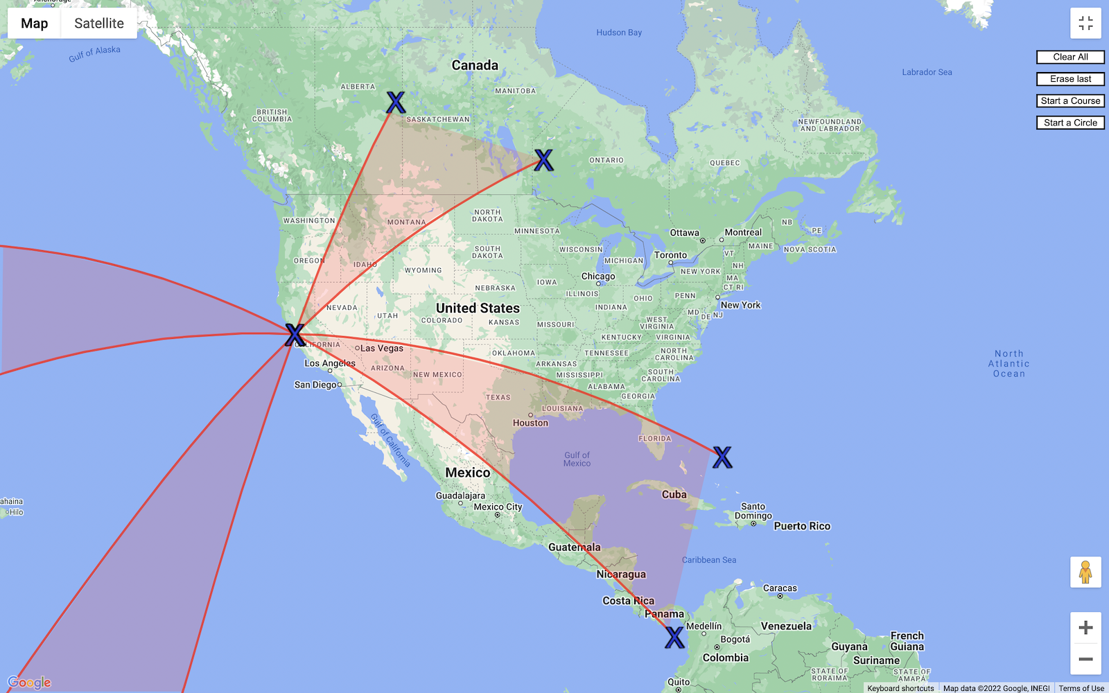
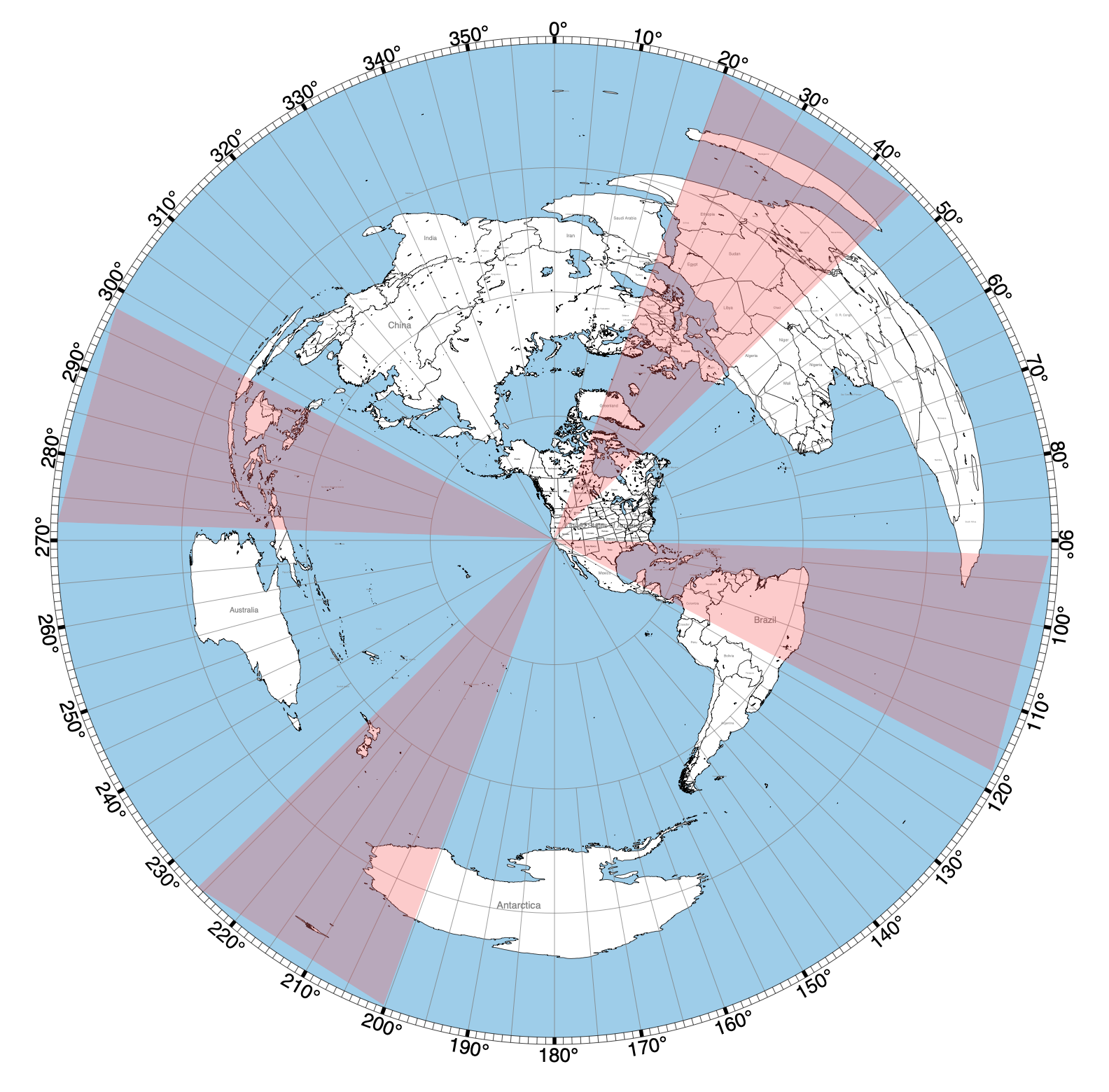
My experience so far: With a 20 watt Xiegu G90 radio and a home-made end-fed halfwave antenna, I’m able to make single-sideband voice contacts to a distance of 1000 miles, maybe more. But there’s a peculiar directionality to the contacts. On the 40m band, most of the people I can hear are within a few hundred miles of my San Francisco location. On the 20m band, I don’t hear very many local people, but I hear strong clear signals from Seattle, Vancouver, Calgary, Idaho, and western Montana. I also hear people in Arizona and Texas, but not as clearly. Occasionally I can hear people from Europe, Russia, New Zealand, and Australia. But I hear virtually nothing from Utah, Colorado, the midwest, or eastern USA. This map shows the approximate effect. I’ll talk more about where this came from in a minute.
Radiation Lobes and Gain
The EFHW antenna wire is about 10m off the ground (the highest trees in my yard), and 20m long, so it’s a half wavelength when operating on the 40m band. That makes it a classic halfwave antenna, with a figure-eight radiation pattern showing two main lobes extending perpendicular to the wire:
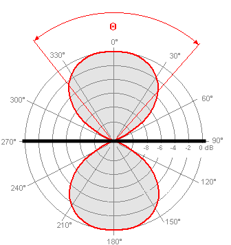
This shows a top-down view of the radiation pattern for a wire oriented east-west. The antenna has gain to the north and south. This gain isn’t like a powered amplifier’s gain, since the antenna is a passive device. The “gain” means that relative to a reference antenna, this antenna radiates better in particular directions, and is also more sensitive to signals coming from those directions. In this case, the antenna would be great for communicating with someone to the north or south, but terrible for someone directly east or west.
40m Operation
My EFHW antenna is oriented roughly north-south, on a bearing of 339 degrees from true north. So I should be seeing nice gain to the west (ocean) and east (most of the USA) right? Not so fast. That figure-eight shows the horizontal radiation pattern, but what about the vertical pattern? It turns out that the height of the antenna is very important, because the radiation pattern interacts with the ground. The rule of thumb is the wire should be at least a half wavelength above the ground, in order for the signal to radiate towards the horizon, where it’s useful.
If the wire is much lower than this, a large amount of the signal will radiate upwards, where it will either reflect straight back down again or else pass into space, neither of which are helpful. Here’s a side view showing the vertical radiation pattern at increasing wire heights:
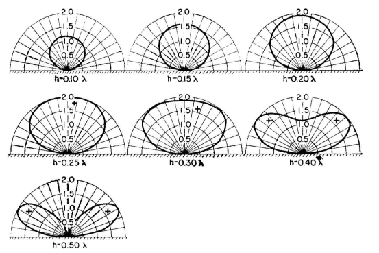
When operating on the 40m band, my 10m antenna height is too low. Most of the signal radiates up at a steep angle, then comes back down nearby. This explains why most of the people I can hear on 40m are within a few hundred miles.
20m Operation
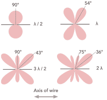
The EFHW also resonates on harmonics of 40m, including 20m. When operating on the 20m band, my 10m antenna height is just right, so I should see nice gain to the east on the 20m band? Nope. It turns out that the classic figure-eight radiation pattern only applies when the wire’s length is a half wavelength. On the 20m band, the wire is a full wavelength. That creates a four-lobed radiation pattern, where each lobe is centered +/- 54 degrees from the wire:
That’s not what I originally expected, but it’s not all bad. By focusing my meager 20 watts in specific directions, my signal will virtually disappear in some directions but be comparatively strong in others. An omnidirectional 20 watt signal might be mediocre in all directions.
Applying those +/- 54 degree lobes to the 339 degree wire orientation, there should be four lobes centered at 33, 105, 213, and 285 degrees bearing from San Francisco. The map at the top shows these four lobes, estimating they’re each about 25 degrees wide. Notice that it misses most of the United States. Oops. The lines are slightly curved due to the map projection. On a globe, they appear straight.
There’s a person in Missoula Montana who I’ve communicated with a few times, and his location is smack in the middle of my northeast lobe. He’s running 700 watts compared to my 20 watts, and he’s amazed by the clarity of my signal. If we extend that northeast lobe, it passes over Canada on a polar route and lands directly on the UK and Europe.
That southeast lobe hasn’t been as useful as I would expect. I hear some people in Arizona and Texas, but it’s not as clear as the northeast lobe. I’ve never heard anything from Florida, even though Miami should be in the lobe.
The northwest lobe isn’t very useful. It covers 7000 miles of ocean before reaching Indonesia, then crosses beyond into the Indian Ocean and Antarctica. If you’re wondering how a northwest lobe could be aimed at Indonesia, which is south of the equator, look at a globe. This confused me for a while too.
The southeast lobe is mostly ocean too, but it does encompass New Zealand at its edge. I’ve heard radio operators from New Zealand a few times, but haven’t yet managed to make contact with one.
This azimuth projection map presents the same information, but may be easier to understand:
Hello, Vancouver
There’s one effect I haven’t been able to explain: 20m signals from the Pacific Northwest work better than almost any other location. My very first HF radio contact was near Vancouver: exciting! International radio communication! But when more and more contacts continued to appear in British Columbia and Washington state, this PNW focus became a mystery. Shower thought: do Canadians call Vancouver the “Pacific Southwest”?
If my map is halfway accurate, Vancouver should be close to a null in my 20m antenna radiation pattern. Either my map is wrong, or there’s some other effect providing north-south signal propagation. Proximity to the ocean? Something about similar ionospheric conditions at the same longitude? I don’t know.
Call Me?
If you’re an amateur radio operator living in one of these four 20m lobes, or in Washington state or western Canada, send me a note. I’d love to schedule a time to get on the radio and make contact. We can chat about radio stuff, or vintage computer stuff, and exchange some ideas. Talk to you soon.
Read 3 comments and join the conversationLearn Morse Code for Fun and Profit

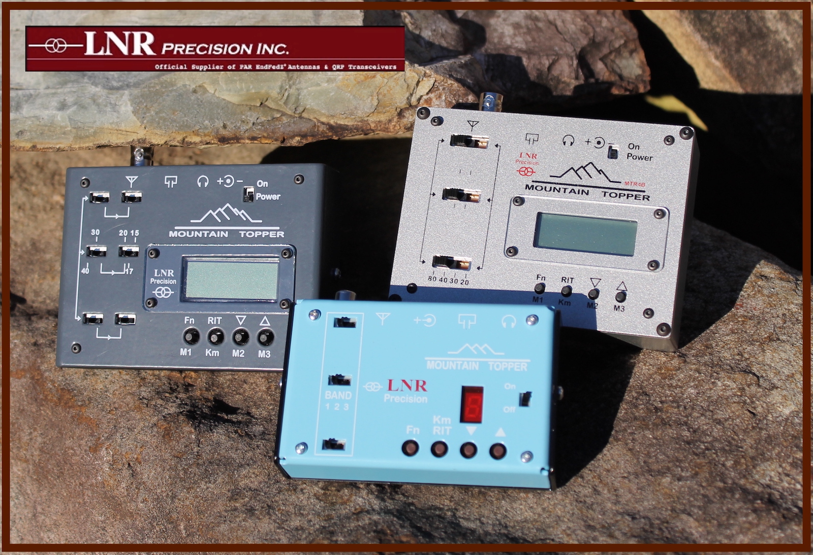
Today is Morse Code Day! You might be surprised to learn that CW (the modern term for Morse) is still widely used in certain corners of the amateur radio universe, not for nostalgia reasons, but because it’s still the best solution to a particular problem. If you want a human-mediated communication method with low transmitter power requirements, good for portable use, and with a very narrow bandwidth (to avoid overlap or interference with other signals), then Morse is your answer. There are plenty of companies making new CW transceivers, like this Mountain Topper series. Maybe their slogan should be “Morse: not dead yet.”
For the past several weeks I’ve been hard at work attempting to learn Morse, spending time each day with trainer software to practice decoding and sending. It’s hard. It doesn’t take too long to learn the dash-dot patterns of the 40-something letters, numbers, and symbols, but it’s hard to be fluent enough to mentally decode them quickly and without conscious thought. Unlike reading a book in a foreign language, you can’t stop and go back over a section where you had trouble. If you ever need to pause and think “what does dash-dot-dash-dash mean again?” then you’re dead. You just need to practice and practice until dash-dot-dash-dash innately sounds like Y in your head, just as much as a spoken word does.
A few decades ago, most people learned Morse by starting at a slow speed about 5 words per minute, which was once the speed requirement for a Novice radio operator’s license in the United States. But at that speed, you can consciously count the dashes and dots, and you naturally construct a lookup table inside your head. You think 1-1-2, oh that’s a Y. But this turns out to be a handicap when you attempt to go faster, and conscious access to a mental lookup table simply can’t go fast enough. The most recommended learning method today is to start learning letters at 18 to 20 wpm, where you can’t easily count the individual dashes and dots anymore, but you learn to recognize the rhythm of each letter, like a snippet of music. But to avoid becoming overwhelmed, extra space is inserted between each letter so the overall average rate is still 10 wpm or less.
Experienced CW operators tell me that learning to send Morse is actually easier than learning to receive and decode it. I’ve been practicing receiving for several weeks, but only just started sending practice a few days ago.
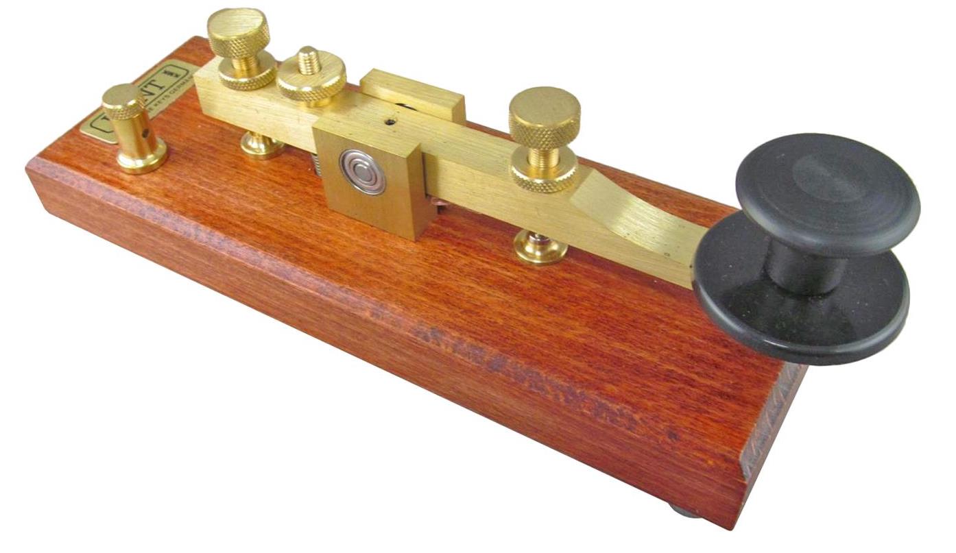
The technology used for sending Morse has changed over the decades. In old movies you see people making tap-tap-tap gestures on a single lever, that’s called a straight key. These aren’t used much anymore, but they’re easy to understand. As long as the key is held down, the radio emits a tone, and the operator has full control over the speed and relative duration of dashes and dots and the gaps between them. This allowed operators to develop a distinctive keying style called a “fist”, which others could use to recognize them even if they weren’t explicitly identified. For example, an operator might have a habit of slightly rushing the last dot in R, or using a particular uneven spacing between the elements of C.
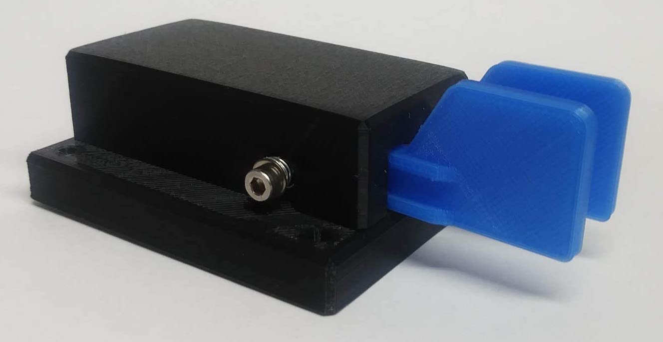
Today most CW operators use a device called a paddle, along with an electronic keyer. The paddle has two levers that are pushed horizontally rather than vertically, one paddle for dashes and one for dots. A circuit in the electronic keyer emits a perfectly-timed series of dashes or dots for as long as the corresponding paddle is pushed. There’s also a simple form of “type ahead”. If you push the dot paddle while a dash is being transmitted, the keyer will emit the dot after the dash is finished, with exactly the right gap between them.
VBand is a fun web-based tool for experimenting with Morse code along with other beginners. You can use keyboard keys as if they were the levers on a paddle, then jump into a chat room and have a horribly fractured conversation with a stranger.
An odd bit of trivia: the original code developed by Samuel Morse in 1838 is not what’s used today. That code was retroactively named American Morse Code, after the rest of the world adopted a different version. American Morse is rather strange, and is now more-or-less extinct. Everybody today uses International Morse Code. Score one for standardization.
Read 4 comments and join the conversationIntentional Unintentional RF for Sneaky CW Transmissions
An unintentional radiator is a device that emits radio frequency signals, even though it’s not intended to. Usually this happens as a result of poor circuit design or inadequate shielding, and it’s a problem. For sneaky purposes, an unintentional radiator can also be used intentionally to send a weak radio signal that carries real information, instead of just causing interference. For example, see this DDR SDRAM hack that uses carefully-timed memory accesses to transform memory bus traces on the PCB into a WiFi antenna, transmitting signals from air-gapped computers.
I’ve started wondering if a simpler version of the same idea could be used to send Morse code transmissions on standard ham radio bands. For example, say you have an Arduino with a built-in LED. If you use PWM to toggle the LED on and off at 7.4 MHz, and tune a radio that’s sitting next to the Arduino to 7.4 MHz CW, I think you would hear a steady carrier. By programmatically enabling and disabling the PWM, you could create the dots and dashes of Morse code. It might take a little experimentation to discover which traces on the Arduino PCB radiate best, at what frequencies. But this kind of thing seems to happen often enough by accident, so it maybe wouldn’t be hard to do it on purpose.
A more interesting avenue would skip the Arduino, and work directly on a typical computer. Is there some Javascript code you could write that would abuse the hardware APIs to enable and disable some oscillator on the computer whose frequency is in a standard ham band, that might unintentionally radiate a very weak signal, and that can be programmatically switched on and off to create Morse? For example, you can do USB HID stuff now through Javascript, and a USB cable might make a nice antenna. Or maybe try some carefully-timed sequence of RAM or SSD access. Or somehow abuse the camera API or anything else that would involve switching signals in the tens to hundreds of MHz range.
The end result could be like magic: just visit a web page in your browser, then tune a nearby radio to the right frequency, and hear a Morse code message. It would be like playing music with floppy drives, except at radio frequencies. Is there any existing proof-of-concept for an idea like this?
Read 4 comments and join the conversationDon’t Cook Yourself With RF Energy
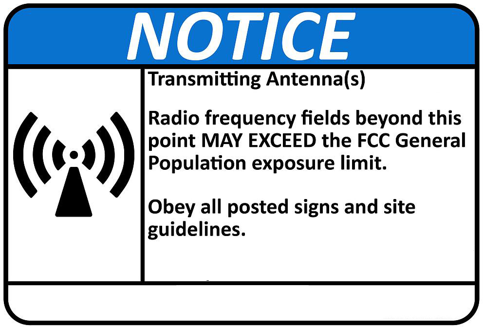
I’m getting ready to install a radio antenna on my home’s roof, and hoping to avoid hurting myself or anybody else in the process. While falling off the roof may be the most obvious risk, a less obvious concern is the radio frequency energy from the antenna when it’s transmitting. Is this something to worry about it? How much RF exposure is too much? Let’s take a look.
Electromagnetic waves in the radio frequency spectrum are what’s called non-ionizing radiation. They don’t have anywhere near enough energy to knock electrons loose from an atom or molecule. Unlike x-rays or gamma rays, they can’t cause radiation sickness, genetic damage, or cancer. The primary human risk from RF is heating up tissue – it can cause burns or literally cook you. This is how a microwave oven works, for example. There’s no risk for a human near an antenna that’s only receiving, but you need to be careful any time the antenna is transmitting. The risk depends on several factors, some obvious ones and some less obvious:
- Transmitter power – Higher power means higher RF energy levels.
- Distance from the antenna – The closer you are to the antenna, the higher your exposure.
- Transmitter duty cycle – Exposure is averaged over a period of several minutes. A 100 watt continuous transmission creates equivalent exposure to a 200 watt transmission alternating 1 minute on, 1 minute off.
- Height above ground – Radio waves can bounce off the ground and reflect back up, concentrating more of the total energy in a single spot.
- Proximity to buildings and nearby objects – Radio waves can also bounce off buildings, creating a similar effect to ground bounce.
- Antenna type – RF energy isn’t radiated equally in all directions. Some antenna types concentrate more energy at low elevation angles close to the horizon, or in specific directions. A human in the high-concentration zone will get higher RF exposure.
- Transmission frequency – The human body is most efficient at absorbing RF energy in the 30-300 MHz frequency range, so the risk is higher for radio transmissions in this range.
- Transmission mode: voice, digital, or Morse code – A 100W-rated radio that’s continuously transmitting may not be outputting 100W continuously; it depends on the transmitted signal. Continuous wave (CW or Morse Code) transmissions come closest to reaching the advertised power all the time. FM voice does too. But AM voice and single sideband (SSB, a type of AM) transmissions have an instantaneous output power that depends on how loudly you’re speaking at that moment. If you’re silent, the power is effectively zero.
In the United States, the FCC’s OET Bulletin 65 Supplement B describes the maximum permissible exposure or MPE limits for RF electromagnetic fields, and some methods used to calculate the exposure. MPE limits are defined in terms of power density (units of milliwatts per centimeter squared: mW/cm 2), electric field strength (units of volts per meter: V/m) and magnetic field strength (units of amperes per meter: A/m). Fortunately you don’t need to understand the details of all this, and can simply use their data tables to determine how far away people must be from the antenna in order to stay safe.
Controlled and Uncontrolled Exposure
The FCC sets two different MPE limits, for controlled and uncontrolled exposure. The controlled limits are higher, and they apply when people know they’re close to an antenna and have been trained to understand the potential risks. Typically this would mean a workplace setting, but controlled exposure limits also apply for licensed amateur radio operators and their families, assuming they’ve had RF safety training. The uncontrolled exposure limits apply to the general population, who may be completely unaware of the risks or who don’t know there’s an antenna present.
I don’t understand the reasoning behind this. Just because someone knows there’s an antenna, and has received RF safety training, how does that make their body less susceptible to injury from RF energy? If you can explain this, please do. For my home, I’m choosing to use the stricter uncontrolled general population exposure limits even though I’m not required to.
Doing the Math
Let’s look at some specific numbers. I’m installing a dual-band VHF/UHF antenna that’s a clone of the Diamond X30. It transmits at about 145 MHz for VHF, or about 450 MHz for UHF. It’s a vertical antenna with an omnidirectional radiation pattern in azimuth, but the pattern is squished vertically. More energy is radiated straight out toward the horizon, and less energy up or down where there’s usually nobody to talk to anyway. The radiation pattern is like a flattened donut, with the antenna centered at the hole in the middle.
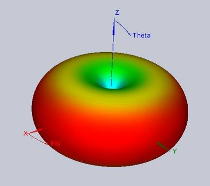
This particular antenna has a gain of 3.0 dBi for VHF and 5.5 dBi for UHF. This gain isn’t true amplification, it’s just a measure of how concentrated the RF energy is in the direction of interest relative to a hypothetical reference antenna. The “gain” comes from the degree of squishing in that radiation donut.
The radio uses standard FM modulation, and has a maximum output power of 25 watts, although most of the time I’ll probably run it at lower power.
Marshalling all this information, we could use the data tables in the FCC bulletin to estimate the minimum safe distance from the antenna for uncontrolled exposure. Fortunately several people have created easy-to-use calculators based on the FCC data, so let’s use this RF exposure calculator from Paul Evans VP9KF. Plugging in 25 watts, 3 dB gain, 3 meter distance, 145 MHz, with ground reflection, the calculator tells us 3 meters is safe and 2.27 meters (7.45 feet) would be the minimum distance. With 5.5 dB gain at 450 MHz, the safe distance is 2.47 meters (8.1 feet).
Going the Distance
8.1 feet isn’t a huge distance, but neither is it small. I probably don’t want to put that antenna directly outside the window from where I’ll operate the radio, or on the roof directly overhead that spot. Nor should it be anywhere that somebody might come and sit within 8 feet of it for an extended period of time. This might not be easy to achieve.
It’s important to understand that this 8.1 feet number is the most pessimistic and conservative number. It assumes my radio is continuously transmitting 100 percent of the time, which it certainly won’t be. It assumes the 25W from the radio is completely radiated as RF energy, when in fact some energy will be lost in the transmission cable to the antenna. It assumes the worst possible ground bounce. And it assumes a person is in the main lobe of the antenna’s radiation pattern, where the energy is concentrated. For this particular antenna, if it’s on the roof and people are below it, their RF exposure will be less because the antenna radiates most energy horizontally rather than up and down.
My planned location for the antenna is on a mast, mounted above the second story roof, above my garage. Yes my garage is on the second story of my home. Ideally the mast would be as tall as possible, but to minimize the visual impact and possible neighbor complaints, I’ll be using a very short mast – about 1 foot. If someone were standing at the back of my garage for an extended period of time, they’d be about 5 feet below the antenna. This might be a small concern, although it still meets the MPE for controlled exposure even before considering all the mitigating factors just mentioned. Outside the garage, it’s impossible to get closer than about 13 feet to the antenna unless you’re standing on the roof. We should be fine.
Read 11 comments and join the conversationInternational Space Station Downlink!
I downlinked a data transmission directly from the International Space Station! This amateur radio stuff is getting exciting. Using an orbital tracker tool, I found the time and location when the ISS would pass overhead here. From 9:16 AM to 9:21 AM, rising to the south, reaching its zenith to the southeast with 19 degrees elevation above the horizon, and setting to the east. I went to the top of a hill in my neighborhood, tuned my simple handheld radio to 145.800 MHz, pointed the antenna, and waited. And suddenly I heard crazy beeping! Dog walkers were staring.
Supposedly you should hold the antenna horizontally for best results, and perpendicular to the line to the ISS. But I just sort of waved the antenna around frantically, searching for the orientation that brought in the cleanest signal. I used the voice recorder app on my phone, holding the phone up to the radio speaker to record the beeping audio, while the wind made noise and cars drove by and the signal faded in and out. I captured almost all of one two-minute transmission and part of another, before the ISS went out of view. It was several minutes of recorded whistling and beeping.
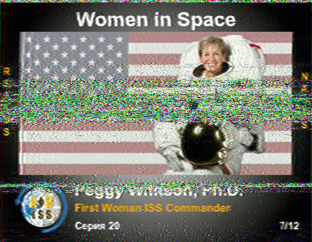
Back home, I used some software called MMSSTV to decode the recorded audio, which was a PD120 slow-scan television image transmitted from the ISS, part of a special event celebrating women in space. The software provides options for tweaking the signal sync, phase, and image slant, because the Doppler shift screws up the signal when the ISS is moving by at 17500 miles per hour. Here’s the final decoded result. Peggy Whitson PhD, first woman ISS commander. Transmission received directly from Earth orbit, Sputnik style. Good morning!
Read 1 comment and join the conversationMy First Amateur Ham Radio Contact Attempt
My new interest in amateur radio is taking off. After a couple of weeks studying, I took the ham Tech and General license exams on Saturday, and passed them both. Today the FCC updated their license database and created a new call sign for me, which means I can now legally transmit on the amateur radio bands. With my freshly-awarded operator’s license and a new radio, I tried getting on the air for the first time. It didn’t go exactly according to plan.
Read 1 comment and join the conversation