

Archive for the 'Floppy Emu' Category
Floppy Emu Hardware Failure Analysis Results
Nobody enjoys troubleshooting non-working hardware, and I’m no exception. Every time I ask a contract manufacturer to assemble a batch of more Floppy Emus, there are always a few that don’t pass QA testing. What happens with those? For several years the accumulating QA failures have been sitting in a pile in the corner of my office, along with a few customer returns, all waiting for the day when I would dedicate time to their investigation. It was a long time coming, but “Failure Analysis Day” finally arrived, or more like Failure Analysis Month, and the results were pretty interesting.
Here’s a breakdown of the unique causes of failure that I identified, and the number of boards affected by each cause.
| Hardware Issue Diagnosis | Count |
| clock crystal / no clock | 26 |
| clock crystal / bad clock | 16 |
| bad CPLD chip | 6 |
| microcontroller not programmed | 5 |
| soldering problems | 5 |
| bad microcontroller chip | 4 |
| broken display header | 1 |
| missing component | 1 |
| cracked PCB | 1 |
| no issue, good board | 1 |
| unknown, couldn’t resolve | 2 |
Clock Crystal
This was a strange failure that required a lot of time to track down initially, but once I learned to recognize the symptoms, I realized that most of my QA failures were due to this problem. I wrote about the clock crystal mysteries in more detail in a separate post last month. The short story is that during my most recent manufacturing batch, my normal supplier of clock crystals was out of stock. The contract manufacturer, with my approval, substituted a different crystal with the same specs. It shouldn’t have affected anything. But somehow it did.
26 of the QA failures appeared to have no functioning clock at all. The board utterly failed to do anything when the microcontroller clock source was changed to the external crystal. A further 16 displayed some level of function, but with erratic behavior or failures at higher clock speeds. Initially I wasn’t sure whether this was due to the newer crystals exposing some defect or fragility in the Floppy Emu design, or whether it was simply caused by defective or damaged crystals. Eventually I came to the opinion that the crystals were damaged by rough handling or overheating during assembly. Replacing the crystals and reprogramming the boards resolved all the issues.
CPLD Chip
The Xilinx CPLD chip on the Floppy Emu is a delicate flower that has long been a source of challenges. Prior to this year’s crystal-gate debacle, the CPLD was the single biggest source of failures that I’d observed. As the chip that’s directly connected to the Floppy Emu’s external interface, it bares the brunt of any static discharge or electrical stress. It’s a 5V-tolerant 3.3V part, but its 5V tolerance has sometimes seemed a bit questionable, at least in the way it’s used here.
Symptoms of a failed or bad CPLD can include disk emulation failures, overheating, or erratic behavior. Usually the device will still be functional and text appears on its display, but the disk features no longer work. In extreme cases the failed CPLD acts as a hard short-circuit from power to ground, and then nothing works. Replacing and reprogramming the CPLD resolved all of the problems with these boards.
Microcontroller not programmed
Amusingly, or depressingly depending on your perspective, the third leading cause of QA failures was that the microcontroller simply wasn’t programmed. Somebody fell asleep at the switch at the contract manufacturer, lost track of what they were doing, put a PCB in the wrong pile, or whatever. A board with an unprogrammed microcontroller will appear completely dead at first glance, but it still responds in the debugger and it only takes a few seconds to flash the chip and get everything working.
Soldering problems
Every component must be electrically bonded to the PCB with solder. Soldering problems can be tough to spot with the naked eye, but usually jump out under magnification, so one of my first troubleshooting steps is usually to look at a problematic board at 10x. I really should get a cool desktop microscope, but for the moment I’m using a cheap 10x jeweler’s loupe which works well enough.
A couple of boards had too much solder in places, resulting in a solder bridge that unintentionally connected two adjacent IC pins. But it was more common to find joints with insufficient solder or poor solder joints, where an IC pin was sort of resting on the PCB pad without actually bonding to it. Fortunately both problems were easy to fix with a soldering iron and a bit of flux.
Bad microcontroller chip
The onboard microcontroller trip is another potential source of failure. In my experience, these microcontrollers are pretty robust, and the only failures I have seen are caused in the field when customers accidentally connect the Floppy Emu cable backwards to their Apple II Disk II controller. This is distressingly easy to do, since the Disk II controller has bare pin connectors instead of a shrouded and keyed header. A backwards connection results in +12 and -12 volts applied to the mcu’s pins, killing it.
Unfortunately the symptoms of a bad microcontroller are nearly identical to the symptoms of a bad clock crystal: a completely unresponsive board, with no debugger activity. I had to review each non-responsive board’s history in order to guess which issue was at fault. In some cases I guessed wrong, and I ended up replacing the microcontroller, and then when that didn’t help, also replacing the clock crystal.
Other
The remaining issues were all one-offs. One board’s display header was physically broken and missing a pin, resulting in a blank display. Another board failed QA because the LED didn’t illuminate, except there was no LED! There was only a blank pad on the PCB. I also encountered a failure due to a PCB that was physically cracked, a long line running down the breadth of the PCB that could only be seen clearly under light from a specific angle. Two more boards defied my efforts to pinpoint the cause of their failures, and after spending too much time on them, I threw them into the scrap bin.
The very last board that I examined turned out to have no problems at all. I tested it extensively and it worked perfectly. This might have failed QA due to something external like a bad power supply or cable, or maybe it was simply miscategorized.
Final results
Of 68 Floppy Emus in the failure analysis heap, I managed to resuscitate 65 of them. That’s a pretty solid percentage! I learned to recognize the symptoms of certain failure causes, so I can address them faster if I see them again. More importantly, the failure analysis learnings (especially about clock crystals) will also help guide me in making design and assembly process changes, so I can reduce the number of future QA failures. Knowledge is power, as they say, and now I have lots of power.
Be the first to comment!Adventures in Microcontroller Circuit Debugging
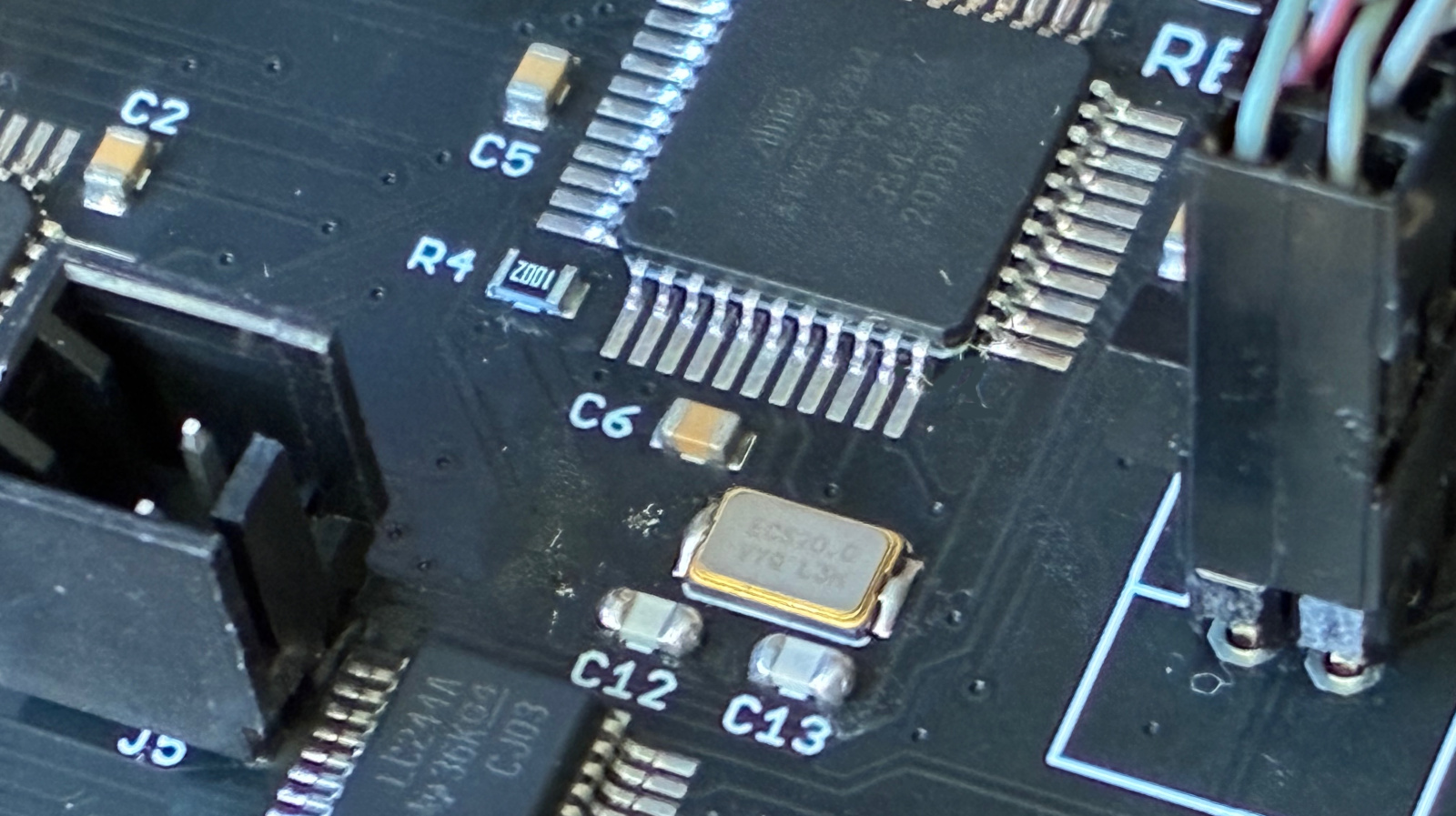
How do you go about troubleshooting a misbehaving microcontroller circuit? A few months ago I manufactured a new batch of Floppy Emu disk emulators. A number of them failed QA at the factory, with a set of symptoms that I’d never seen before in all my years of developing this device:
- Most of them simply wouldn’t boot up at all, despite verifying that power was good and the mcu was correctly programmed.
- Some exhibited “haunted” behavior, seemingly jumping to random sections of the mcu program code, outputting messages on the display that made no sense given the context.
- One of them appeared to work in slow motion, with LED blinking and display updates noticeably more sluggish than normal.
This was odd, to say the least. I have a lot of experience with the ATMEGA1284 microcontroller and the Floppy Emu circuitry that surrounds it, and I’ve become an expert at guessing what’s wrong based on the symptoms of misbehaving boards. These were all new and bizarre symptoms to me. Might they arise from different problems, or could they all point to one common underlying issue?
My intuition suggested some kind of systematic assembly problem. My contract manufacturer used a new subcontractor for this batch of Floppy Emu boards, so maybe a silent change to the process caused an unexpected issue? Parts substitution? Bad parts? Counterfeit chips? These QA failures sat in a pile on my desk for months, waiting for answers.
Probing, Poking, and Theorizing
Yesterday I finally decided to concentrate on the “won’t boot” devices, since that seemed like the most tractable problem. I put a few boards in a test harness, and connected power and a hardware debugger. The power supply voltages looked good. No obvious soldering problems were evident, but just to be sure I reflowed the solder on a few boards, without seeing any improvement.
On many of the boards, the hardware debugger could talk to the microcontroller and I was able to confirm the chip was correctly configured and programmed, but the program didn’t seem to actually run. At power-up the boards did… nothing. And with a smaller number of the boards, the debugger could not communicate with or even detect the chip. What could cause these symptoms? I brainstormed:
- Bad power. Seemingly ruled out by my measurements.
- Misprogrammed chips. I confirmed the configuration and reprogrammed several, without improvement.
- Bad chips.
- Chips stuck in reset.
- Clock problems.
- Problems with other circuit components (SD Card, CPLD, etc) causing electrical or program failures.
A batch of bad microcontroller chips seemed like the most likely explanation, so I desoldered the ATMEGA1284 from a board and replaced it with a new one from my stash. But after configuring and programming the chip, the board behaved the same as before, refusing to boot. That seemed to rule out problems with the chips themselves.
In the Floppy Emu program code, when the device first powers up, there’s some communication with the SD Card and the CPLD that happens before anything is drawn on the device display. I suspected that something might be going wrong during those steps, causing the program to freeze or crash and resulting in a blank display. To test this, I modified the program to blink the status LED twenty times as proof of life at the start of main() before doing anything else. Yes, with all the hardware tools at my disposal, I was back to caveman debugging with a blinking LED.
But there was still no joy, no LED blinking, no apparent program activity at all during power up. What the hell? Here I had a good microcontroller with good power, confirmed programmed correctly, in a circuit and board design that’s been in successful use for years. It wouldn’t even blink an LED. Since the blinking should have happened as the very first step of the program, its absence mostly seemed to rule out explanations related to failed interactions with other circuit components like the SD Card. So I focused in on the reset signal and the clock, the only two possibilities that I had left.
Clock Crystal Mysteries
Floppy Emu’s microcontroller uses an external 20 MHz crystal for speed and precision, but it also has an internal built-in 8 MHz oscillator. This particular board was still communicating OK with the hardware debugger, so for grins I tried changing the chip’s fuse configuration to select the internal 8 MHz oscillator as the clock source. Lo and behold, it worked! The device booted up and appeared to run normally, although obviously at only 40 percent of normal speed. I confirmed the same result with a few other boards – when I was able to get debugger communication and change the clock source to the internal oscillator, the board would boot. This wasn’t a fix, since the Floppy Emu won’t actually work correctly with an 8 MHz oscillator, but it was proof of major trouble with the external clock crystal.
If an external crystal isn’t working reliably, the microcontroller won’t have a reliable clock source. It will probably fail to run at all, or else act super glitchy. It will also cause problems with debugger communication. This all sounds a lot like my observed symptoms.
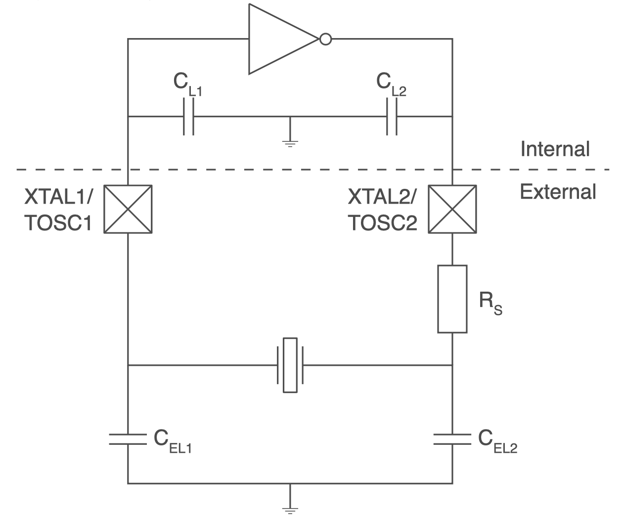
So let’s talk about this crystal oscillator circuit. Like almost all microcontrollers, the ATMEGA series has built in amplifier hardware to drive an external piezo crystal and force it to oscillate, using a circuit that I believe is called a Pierce Oscillator. I should know more about the theory of operation, but I’m mostly ignorant. What I know is that you connect the crystal’s two terminals to two ATMEGA pins using the shortest PCB traces that are practically possible, and add two external capacitors with values in the picofarad range, whose values are determined by a formula, and then everything works.
Investigating a bit further, I observed that all of the problem boards used a different crystal manufacturer than I have used previously. That’s fine, it shouldn’t have been an issue, but it seemed important given the circumstances. Previous editions of the board used this NDK crystal, but these troublesome boards substituted a similar ECS crystal. Both used the same physical footprint and advertised an 8pF load capacitance.
Speculations and Next Steps
As of today, that’s as far as I’ve gone with direct debugging, but I’m continuing to search for a smoking gun explanation. Maybe I got a batch of bad crystals? Possibly, and I can try reworking a board and replacing its crystal, but that explanation seems not very likely to me.
What about those two capacitors that form part of the oscillator circuit? Their values are important to the oscillator operation, and if the value is too far off from the optimal value, then the crystal won’t oscillate correctly or won’t oscillate at all. These tiny SMD capacitors bare no markings, so there’s no way for me to confirm visually that the capacitors are the correct ones. Maybe the subcontractor used the wrong value of capacitors on some boards? Speaking of which, what is the correct value?
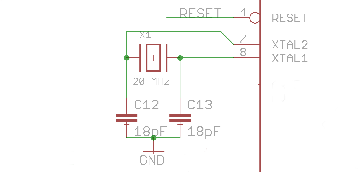
Here we enter into a bit of Pierce Oscillator analog voodoo that I don’t understand very well. The correct value of the two external capacitors is given by the formula Cext = 2 * (Cload – Cstray). Cload is the crystal’s load capacitance: 8pF in this case. Cstray is a measure of the stray capacitance of the microcontroller pins and PCB board traces. There’s no simple way to measure this directly, but for short traces on a two-layer PCB, I’ve seen estimates around 3pF to 5pF. Let’s call it 4pF. So Cext = 2 * (Cload – Cstray) = 2 * (8pF – 4pF) = 2 * (4pF) = 8pF. In theory then, I should have two external 8pF capacitors paired with the clock crystal. In reality, the capacitors are 18pF.
18pF external capacitors. I don’t remember how I originally specified this value; it’s lost in the mists of time during Floppy Emu’s initial development phase. But looking at it again now, it certainly seems “not ideal”. The oscillator circuit can be fairly forgiving and the ATMEGA driver amplifier can work over a broad range of capacitance values, which is probably why I never noticed an issue before. But 18pF is not mathematically correct. My guess is that the oscillator circuit has been operating close to the margins, and now there’s something different enough about this ECS crystal, its ESR or stray capacitance maybe, that pushes the circuit far enough out of its comfort zone that it stops working entirely.
So now what? How can I confirm this theory and fix the issue? One possibility is modifying the ATMEGA’s crystal driver behavior by changing a fuse setting. I normally use the low-power crystal oscillator mode, which applies a driving voltage in the millivolts range, but there’s also an option for full-swing crystal oscillator. In theory this setting should work better in cases like this where the external capacitors are outside the optimal range of values. To test this, I altered the fuses on one board to enable the full-swing oscillator behavior, and… it didn’t work. The board still wouldn’t boot up, and it also stopped communicating with the debugger, so it’s now effectively a brick.
That leaves me with the possibility of reworking the boards and swapping the external capacitors for 8pF replacements. Or maybe 10pF or 12pF if I want to stay closer to the original design value, since problems can also arise if the value is too low as well as if it’s too high. Unfortunately my workshop doesn’t stock any appropriate capacitors in that range. I’ve ordered a variety of values to use for testing, so the conclusion of this mystery will need to wait until then. Stay tuned…
Read 22 comments and join the conversationNew Product and Mea Culpa
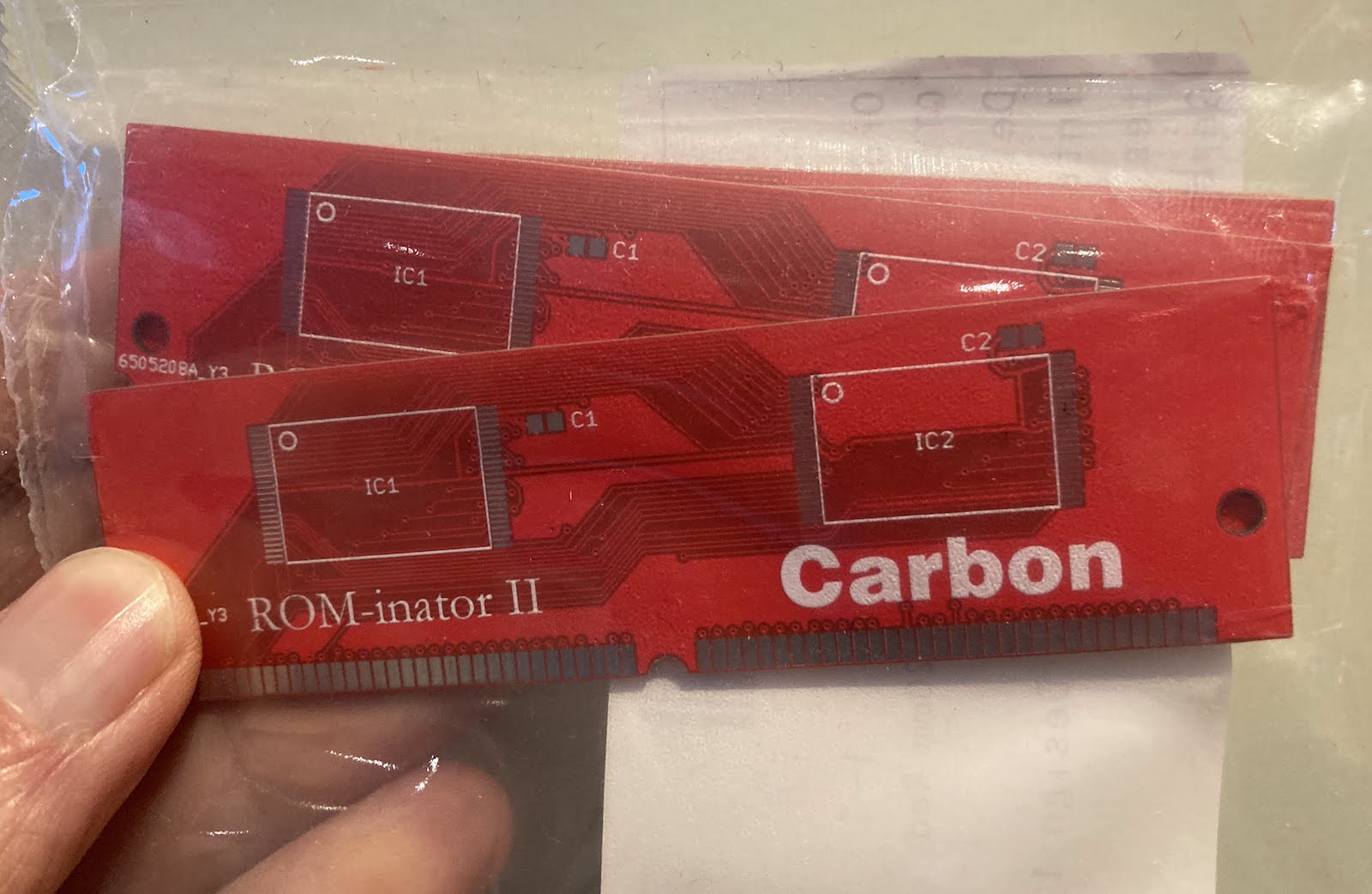
Today I’m happy to share a long-overdue new product announcement, as well as a firmware update for the BMOW Floppy Emu disk emulator.
The new product is an updated Macintosh ROM SIMM, the Mac ROM-inator II Carbon, which has replaced the ROM-inator II Atom. The Carbon has already been in the BMOW store for several months, but I never got around to formally announcing it until today. Like all versions of the ROM-inator II, the Carbon offers a great upgrade for the the Macintosh SE/30, IIx, IIcx, IIci, IIfx, and IIsi, offering a bootable ROM disk, 32-bit cleanliness, HD20 hard disk support, and more. The Carbon has twice as much memory (4 MB) as the previous ROM-inator model, which enables the storage of a substantially larger compressed ROM disk. The Carbon’s ROM disk contains a full version of System 7.1 along with a suite of recovery/diagnostic utilities that have proven useful. Compared to the Atom, the Carbon has a larger selection of utilities and games, and the System folder is more amply populated.
Version 250225A of the Floppy Emu firmware addresses a bug that affected some WOZ disk images for Apple II computers, causing them to fail to load correctly, and making it difficult or impossible to format WOZ images. I only became aware of this bug a few days ago, but determined that it’s been present since November 2022! I am scratching my head over how it could have been broken for so long without me or anyone else noticing. Probably we all chalked up any WOZ problems we encountered to other issues, and didn’t notice that disks that worked in 2021 and early 2022 firmware versions did not work under later firmware versions. If you use WOZ disk images frequently with your Floppy Emu and Apple II, you’ll definitely want to get this update. The Macintosh/Lisa version of the firmware was not affected and has not changed. Apologies for letting this issue go undetected for so long!
Read 1 comment and join the conversationFloppy Emu Deluxe Bundle and Acrylic Case Back in Stock
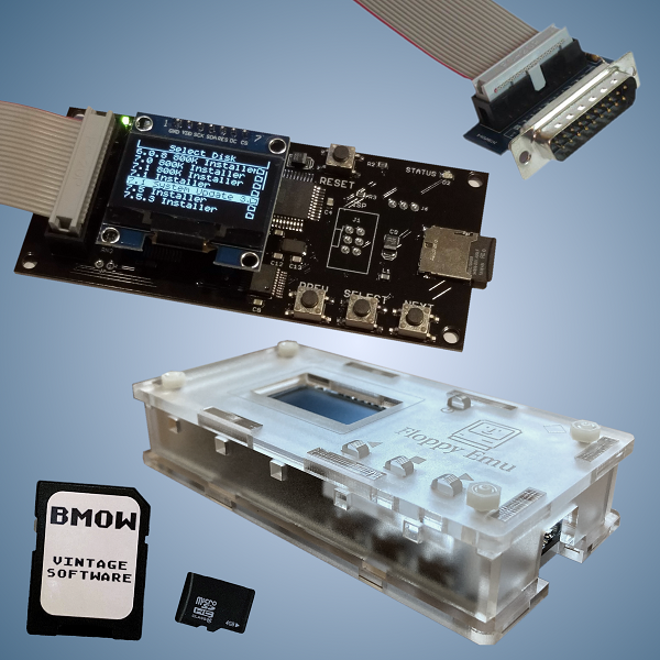
For those who’ve been waiting, the Floppy Emu Deluxe Bundle and the Frosted Ice Acrylic Case are back in stock at the BMOW Store. While you’re shopping, check out the new Mac VGA Sync-inator too!
Floppy Emu is a floppy and hard disk emulator for classic Apple II, Macintosh, and Lisa computers. It uses an SD memory card and custom hardware to mimic an Apple floppy disk and drive, or an Apple hard drive. The Emu behaves exactly like a real disk drive, requiring no special software or drivers. It’s perfect for booting your favorite games and software, or transferring files between vintage and modern machines. Just fill your SD card with disk images, plug in the Emu board, and you’ll be up and running in seconds.
Read 4 comments and join the conversationFloppy Emu update: StuffIt file support, CD-ROM and SCSI image support, more
Vintage Macintosh fans, here’s a firmware update for the BMOW Floppy Emu disk emulator with some exciting new features that I’ve been working on for the past few weeks. Please give this version femu-231209M a try, and let me know how it works for you. Even a basic report of “it works fine, I have nothing more to say” is helpful.
StuffIt File Support via Boxing
Archive files like StuffIt .sit, BinHex .hqx, MacBinary .bin, Compact Pro .cpt, and text .txt can now be directly used as if they were floppy disk images, with a new feature I’m calling “boxing”. Select a .sit file (or other archive) on your SD card, and Floppy Emu will automatically create a temporary disk image “box” that contains the file. From the user’s point of view, this basically makes StuffIt files and other archive files behave as if they were disk images, and it’s a major time-saver and quality of life improvement when you’re downloading software from The Garden and using your Floppy Emu to transfer it to your Mac.
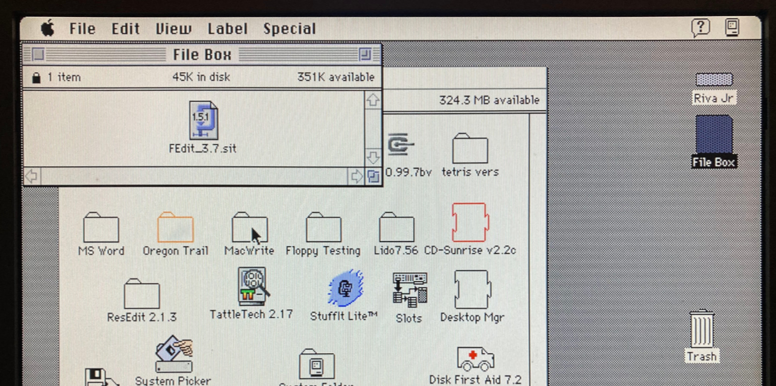
Floppy Emu generates a read-only box disk that’s the smallest possible size to contain the StuffIt archive file: 400K, 800K, or 1440K. Your Mac will need to have support for the larger floppy disk sizes in order to transfer larger StuffIt files. 400K box disks are HFS, not MFS, so you’ll need to be running System 2 or later.
Macintosh Hard Disk support for Zulu SCSI, Blue SCSI, and CD-ROM images
For Mac models with support for HD20-type hard disks, Floppy Emu can now use disk images in SCSI device or CD-ROM formats, with an embedded Apple Partition Map, such as the disk images used with Zulu SCSI or Blue SCSI. Supported formats are HDA, IMG, ISO, CDR, DSK, and TOAST. When browsing for disk images in the Floppy Emu directory menus, these images will appear with an APM suffix, while traditional disk images will appear with an HFS suffix. For APM images, Floppy Emu will search the partition map and mount the first HFS partition in the image, ignoring driver partitions and other boring stuff.

Yes, this means Floppy Emu is now a CD-ROM emulator (sort of) – see above with a CodeWarrior CD mounted. CD-ROM images are mounted as read-only hard disks, not as removable media, and the speed is comparable to a 1x CD-ROM drive. It won’t replace a dedicated CD drive, but it’s great for installing software. If you’re running System 6, you may see an error message when using CD-ROM images complaining that the desktop file couldn’t be created because the disk is locked, just like you would with many real CD-ROMs and System 6. The INIT Desktop Manager 2.01 will fix this. With System 7 or later, it’s not needed.
Other Stuff
The Floppy Emu Model C also received some UI improvements and polishing. A “Settings Menu…” item has been added to the top level of the menus, providing an alternate way to return to the settings menu without needing to reset the device. The “..” directory menu item for returning to the parent directory was something that only a UNIX nerd could love, and has been replaced with “Go Back” and a curly arrow icon. Most error messages or dead-ends in the UI flow now have a way to exit or return, so it shouldn’t ever be necessary to use the RESET button to perform a hard reset of the device.
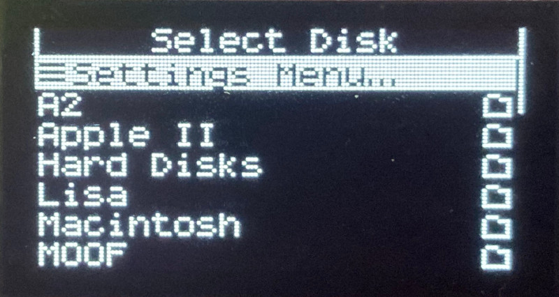

A new version of the Apple II firmware with these same UI improvements is also available. Have fun, and don’t forget to leave feedback on how it works for you!
Read 12 comments and join the conversationFloppy Emu Update: GS/OS Errors, Dual-Drive Automount, More
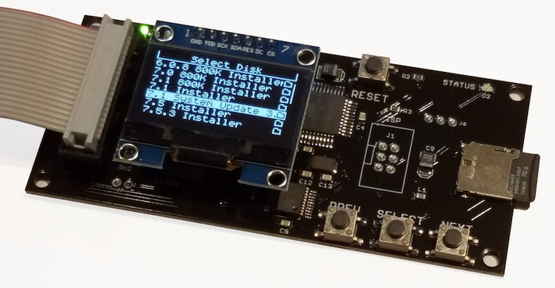
Here’s a new firmware update for the BMOW Floppy Emu disk emulator! This update has several small improvements and fixes for the Emu’s Apple II disk drive emulation modes.
Overrun Errors in GS/OS
The new firmware resolves a problem that could cause a “Fatal Error: Overrun” on the Apple IIGS with GS/OS. This error would appear when using Smartport hard disk emulation mode, with more than one hard disk image mounted, if you repeatedly exited and re-entered GS/OS (by exiting to BASIC or another ProDOS8 application).
I call the issue “resolved” rather than fixed, because the root cause is still not clear. What I found is that when exiting GS/OS for the second time, the computer sends a Control packet to the second hard drive (the non-boot drive) with a control code of $40. I haven’t found any documentation about this particular control code or what it’s intended to do. Other control codes are used for functions like ejecting removable media or resetting the disk drive. This particular Control packet has a very large data payload attached – about 1500 encoded bytes or 1300 real data bytes – which was overflowing the Floppy Emu’s receive buffer. Anyone have a guess what the control code $40 might mean?
Dual 5.25 Inch Drive Automount
In Dual 5.25 Inch Floppy emulation mode, automount of the most-recently-used disk now works for both drive 1 and drive 2. Previously only drive 1 supported automount.
Directories with Hundreds of Files
This firmware also fixes a UI problem that would occur if the current directory on the SD card had more than 212 files. Very large directories would exceed the memory capacity of the Floppy Emu, causing incorrect UI behavior. The new firmware will warn you if there are too many files and then limit the directory listing to the first 212. To avoid this, it’s recommended to use a hierarchical directory structure instead of flat directories containing hundreds of files each.
Get the New Firmware
You can download the latest Floppy Emu firmware from here. As always, I appreciate your feedback on firmware updates, whether it’s a problem report or just a “works great for me” confirmation. Enjoy!
Read 2 comments and join the conversation