

Archive for the 'Nibbler' Category
The Vintage Computer Festival is Almost Here!
Vintage Computer Festival West XI is happening next weekend, August 6-7 at the Computer History Museum in Mountain View, California. I’m belatedly dusting off the hardware for my exhibit and preparing the demos and signage. Anybody have a trade show style backdrop they’d like to lend me? 🙂
I’ll be exhibiting three of my hand-made computer creations, each of which has gone through some modifications for the show:

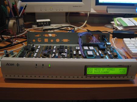
BMOW 1 – My original custom-made CPU and computer that kicked off this blog and my journey into hobby electronics. BMOW 1 is an 8-bit CPU, implemented with 7400-series TTL discrete logic and a few PALs. Built around this is peripheral hardware for I/O, sound, and video. The end result is a custom creation that’s vaguely similar to an Apple II in its performance and capabilities. And it’s all hand wire-wrapped, with thousands of individual wires.
New for VCF West, I’ve cut a porthole in the bottom of the case and added interior case lighting, to showcase the glorious mess of wires inside. I was nervous I’d break something while removing and replacing all the parts in the case, but BMOW survived and is still running strong.
68 Katy – A 68000-powered single-board Linux system that began life as “Linux on a breadboard”. It’s a super-minimal Linux system containing only a 68K family CPU, 512K ROM, and 512K RAM. I began with a 16 year old Linux distro and hacked it to support this hardware and its tiny memory size. The original version was literally built on a breadboard, though the current version is now a PCB with a serial port for I/O.
During testing for the VCF show, I found that 68 Katy was no longer running reliably. I’d previously overclocked the 8 MHz-rated 68008 CPU to 12 MHz. Restoring an 8 MHz oscillator seemed to fix the problems – for now.
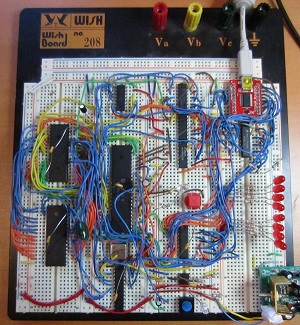
Nibbler – Another custom-made CPU and computer with a 4-bit (nibble) architecture. Designed to be simple to build and easy to understand, Nibbler’s CPU core consists of just 13 discrete 7400-series logic chips – individual counters, registers, buffers, and gates. To complete the machine, it adds a few ROMs and an SRAM, as well as pushbuttons, an audio speaker, and a text display. With a 4-bit CPU and 4K of memory you might think Nibbler couldn’t do anything much more interesting than blink an LED, but it boasts some nice games and demos. Like BMOW 1, it’s all hand wire-wrapped.
Nibbler will see a significant change for the VCF show, time permitting. The original design uses a 4K ROM for storing the program – when you want to run a different program, you need to replace the ROM. I plan to substitute a 16K ROM with a DIP switch to control the highest two address lines, so I can select between four different stored programs without resorting to ROM swapping.
Antique and Custom Computers Galore
Beyond the BMOW stuff, the other exhibits planned for VCF West XI look great! They include Eric Schlaepfer’s MonSter 6502, Bill Buzbee’s Magic-1, vintage DEC and Data General systems, IBM mainframes, Amigas, TRS-80s, S-100 hardware, and much more. Check out the full list here.
The show hours are 9:30-6:00 on Saturday the 6th and 9:00-5:30 on Sunday the 7th. Do you plan to attend? Leave a comment below, and I’ll keep an eye out for you!
Read 1 comment and join the conversationNibbler PCB Build
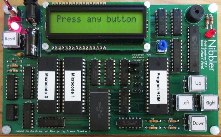
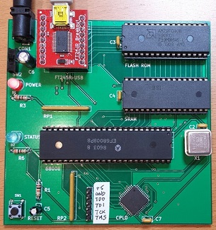
William Buchholz has designed and built a PCB version of my Nibbler 4-bit CPU for his local hackerspace. Nibbler is built entirely from standard 7400 series logic chips – individual counters, registers, buffers, and gates. It’s an educational example of a simple CPU that’s easy to understand and build, but still capable of running games and other interesting programs.
In addition to converting my messy wire-wrap job into an elegant PCB, William also made some component substitutions, including a larger program ROM. Using jumpers connected to the upper 5 address lines, you can select between several different programs without having to reprogram the ROM. More photos of William’s work are here and the schematics and design files are here.
Read 4 comments and join the conversationMastermind Game Rules, and Nibbler Near-Death Experience

And here’s why all your circuits should have some kind of reverse-polarity or over-voltage protection: I nearly killed Nibbler yesterday. I brought the hardware to a friend’s house for a nerdfest party, but when I demoed it, I accidentally plugged in the 9V AC power supply from Mozart’s Credit Card instead of the normal 5V DC supply. I’ve gotten lazy with my circuit designs, preferring to use an external regulated 5V supply instead of including power regulation on the board. Nibbler has no voltage regulator, rectifier, reverse-polarity protection, or fuse, so the 9V AC went straight to the power pins on all the chips. Baaaaaad!
Fortunately my mistake didn’t release the magic smoke from the chips. The speaker buzzed and the LCD showed some strange lines, and at first I thought a wire must have come loose during transport. It only took me about 10 seconds to recognize my error, and luckily Nibbler was fine after switching to the right power supply. If I’d left the 9V AC supply plugged in for longer, I think the board would have been toast.
Square Pegs in a Round Hole
Once Nibbler was up and running, we tried the Mastermind program that I wrote a few months back. It was a hilarious example of how six very smart guys can take fifteen minutes and a lot of arguing to solve a single Mastermind puzzle, but it also exposed some subtleties in the rules of Mastermind that I’d never considered before.
Most readers are probably familiar with the game: a codemaker chooses a four-element secret color code , and a codebreaker tries to guess it. After each guess, the codemaker gives feedback in the form of black or white pegs: a black peg means some element is the right color and in the right position, while a white peg means some element is the right color but in the wrong position. But what does that mean exactly, and what elements does it refer to?
Imagine you’re the codebreaker, and your guess is yellow-red-blue-green:

The codemaker comes back with three black pegs and one white peg:
![]()
Depending on your interpretation of the rules, you may think this is an invalid result, and the codemaker has made a mistake. After all, if three of the guesses are the right color in the right position, then there’s only one incorrect position remaining. The color guess at that position must either be correct (which would result in a black peg) or incorrect (which would result in no peg at all). Right? Wrong!
The critical question is whether the black and white pegs reflect the codebreaker’s guess with respect to the secret code, or the secret code with respect to the codebreaker’s guess. It might seem that it would be the same either way, but it’s not. Translated into pseudo-code, the two possible scoring algorithms are:
Secret-centric algorithm:
for (i in the range 1 to 4) {
    if (secretCode[i] == guess[i]) {
        emit black peg;
    }
    else (for j in the range 1 to 4) {
        if (secretCode[i] == guess[j]) {
            emit white peg;
            break;
        }
    }
}
Guess-centric algorithm:
for (i in the range 1 to 4) {
    if (guess[i] == secretCode[i]) {
        emit black peg;
    }
    else (for j in the range 1 to 4) {
        if (guess[i] == secretCode[j]) {
            emit white peg;
            break;
        }
    }
}
If we assume the secret code is yellow-green-blue-green:

and with the yellow-red-blue-green guess shown earlier, then the secret-centric scoring algorithm will result in black-black-black-white, but the guess-centric algorithm will result in black-black-black.
I think most people play the game using the guess-centric scoring algorithm, without realizing it. It seems more natural, as the score pegs are a reflection of how closely the guess matches the secret code, not how closely the secret code matches the guess. But surprisingly, I can’t find any definitive answer to which algorithm is correct. The online descriptions of Mastermind rules that I’ve found are vague on this point, or contradictory. The Wikipedia description of the rules implies both of these scoring algorithms are wrong, but isn’t specific enough to define an alternate algorithm. This page sounds like the guess-centric algorithm in its text, but the provided example uses the secret-centric algorithm. Unfortunately the official Hasbro game rules for Mastermind to Go only gives one example, which is ambiguous as to which algorithm should be used. The Parker Brother game rules are also ambiguous, and don’t give any examples. But the published rules for Pressman Ultimate Mastermind (which uses five colors instead of four) uses the secret-centric algorithm.
So how can we know which algorithm is the right one? I’m not sure we can. Mastermind is just a modern version of an old pencil-and-paper game called Bulls and Cows, which may date back more than a century. I couldn’t find anything definitive about the origins of that game or the correct rules. Ultimately it doesn’t really matter which scoring algorithm is used, as long as both players agree on it. For Nibbler I chose the secret-centric algorithm. Even though it’s less intuitive to me, it seems to be the most common choice among those people who pay attention to this quirk in the game rules. What do you think?
Read 3 comments and join the conversation
Nibbler Demos!
After fiddling with Nibbler’s hardware and fixing its glitches, it’s time to write some demo software. Let’s see what this little handmade 4-bit CPU can do! Sorry the quality on these videos isn’t the best – try changing the quality setting to 480P to get a bit more picture detail.
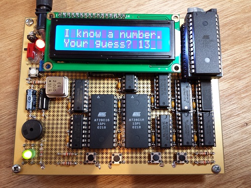
Mastermind
Gamers of a certain age will doubtless remember Mastermind, a code-breaking game for two players, which is based on an old pencil and paper game called Bulls and Cows. The codemaker chooses a secret code that’s four elements in length, where each element can be one of six possible colors. The codebreaker then has ten chances to guess the secret code. After each guess, the codemaker gives feedback in the form of black or white pegs: a black peg means some element is the right color and in the right position, and a white peg means some element is the right color but in the wrong position. The feedback pegs are position-independent, so a black peg doesn’t tell the codebreaker which of the four elements in the guess was correct.
Adapting Mastermind to Nibbler was relatively simple. A few weeks ago I wrote a Guess the Number program for testing purposes, and most of it was reusable for Mastermind. The final program was 2057 bytes, or just over half of Nibbler’s available program memory. Instead of using colored pegs, the code is a 4-digit number, where each digit is between 0 and 5. I added a few little bells and whistles, like button feedback sounds, and a little victory tune when you guess the secret code correctly. The result is surprisingly fun, if you like these kinds of logic puzzles. It works fine in the Nibbler simulator too, if you want to try it out.
Blue Danube
I wanted to focus on music and audio next. Nibbler doesn’t have any real audio hardware, only a speaker that’s directly connected to a digital output pin. Making sounds is as simple as toggling the output quickly between 0 and 1, but making specific sounds at just the right frequency is more complicated. It requires a lot of cycle counting math, to guarantee the speaker will be toggled at exactly the right rate for an A at 440 Hz or a piano’s middle C (261.6 Hz). Each period of the waveform needs to be exactly the same length, even as the path through the inner code loop varies in length due to carry propagation with multi-nibble counters. If one period is slightly off, your ear will hear it.
Setting the duration of each note involves more math, dividing the duration by the period length to find the number of periods to play. That means two notes at different frequencies but with the same duration will have different repeat counts (duration values) in the code, further adding to the necessary bookkeeping.
I started writing a music demo by hand, but it was such a pain that I couldn’t imagine building a whole song that way. Instead, I created a new tool called Music Maker to do the math and code creation for me. It takes song data as input, and generates a Nibbler assembly program as output. The song data is expressed in the Music Macro Language from Microsoft Basic, which you might recall if you ever used GWBASIC’s PLAY command. This simple one-voice text-based format is a perfect match for Nibbler’s limited audio capabilities. Songs are described as a series of notes, with optional length and octave modifiers:
"T180 DF#A L2 A L4 O4 AA P4 F#F# P4 O3 D"
Music Maker saved me a huge amount of effort, but I still needed to hand-edit the generated assembly code to repeat a few musical phrases in the right spots. Because Nibbler’s instruction set isn’t well-suited to storing constant data in programs, the code is fairly bloated, taking 3569 bytes (87% of memory) for a song that’s a few dozen measures long. I chose the Blue Danube for the demo song.
Frogger
For the last demo I wanted to do something really different, so I created a real-time action game using custom graphics. The classic arcade game Frogger leapt to mind. The player must guide a frog across many lanes of traffic and a treacherous river, avoiding a variety of obstacles moving in different directions and at different speeds.

Bringing Frogger to Nibbler presented several challenges. First – graphics. The HD44780 chip inside the 16×2 character LCD screen does support user-defined character fonts, but only for eight characters, which doesn’t provide a lot of variety. Second – screen size. The screen only has two rows, and that’s not many lanes of traffic for our frog to dodge. How can you make a game with that?
Each character on the LCD screen is 5×8 pixels, so the total screen height is 16 pixels. My approach was to divide the screen into four virtual rows, each of which was 4 pixels tall, with two virtual rows per actual row of text characters. Then I created custom character fonts for each possible combination of contents in the cells in the upper and lower virtual rows. Each cell can contain one of three possible items (an obstacle, the frog, or nothing), and there are two cells, so there would seem to be 3×3 or 9 permutations. But because there’s only one frog in the game, the permutation with frogs in both cells isn’t needed, and the remaining eight permutations fit exactly into the HD44780’s eight user-defined character slots. The result is a 16×4 virtual playfield, where each playfield cell is 5×4 pixels. For a bit of added variety, I also made the upper and lower obstacles look visually distinct.

To make the game “real-time”, I needed a way to animate the obstacles while the player was moving. Without interrupts or any other real time-keeping mechanism, I had to add a timeout counter inside the busy loop that checks for button input. After a few thousand checks of the button state, the game jumps to a routine that moves the lanes of obstacles by one position, then returns to button checking. Fortunately it all happens fast enough that you can’t notice any hiccups.
Frogger was the only demo where the lack of an indirect addressing mode really hurt. Tasks like animating the playfield or checking for collisions are just screaming out for indirect addressing. Without it, I had to write code that explicitly copies/checks/moves each of the 64 playfield cells. The result is lots of ugly bloat, and a code size of 3279 bytes (80% of memory).
The final game turned out nicely! The only big flaw is the animation: the persistency of the LCD screen makes objects appear to fade and flicker, but there’s nothing I can do about that. Despite this, it’s a lot of fun to play. In the video, notice that the lanes of obstacles animate at different speeds, and each lane moves in the opposite direction from its neighbors, making the game more challenging than it first appears. If you can navigate the frog upwards from the bottom row, and escape out the top row, you’ll hear a little victory tune. Go Nibbler!
Read 5 comments and join the conversationInvalid Logic Levels Explained
What happens when you feed an invalid voltage level to the input of a digital logic gate? It’s an interesting story. In my last post, I described a subtle Nibbler bug where a combinatorial feedback loop through the ALU caused an invalid voltage level to propagate from an output back to the input, creating a self-sustaining cycle of badness. I fixed the problem by adding another chip to break the loop, but I wasn’t totally happy with that solution. After studying the problem further, and peering into the internal details of the 74LS181 ALU chip, I’ve found a new solution that doesn’t require any extra hardware. The new chip has been removed, and Nibbler still runs flawlessly.
To explain what’s going on, it’s important to understand how basic logic gates like NOR and AND are built from transistors. The diagrams below show gates using FET transistors, instead of the bipolar transistors used in the 7400LS family, but the concept is the same.
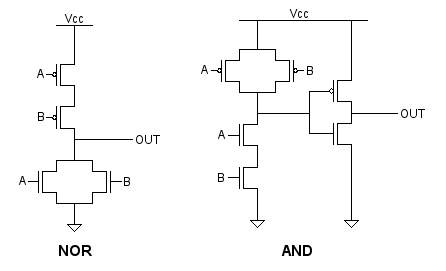
In the NOR gate, if either A or B is above the transistor switching threshold, one or both of the bottom transistors will be turned on. This pulls the output to ground. The top transistors will be turned off. If neither A nor B is above the switching threshold, neither of the bottom transistors will be turned on, but both of the top transistors will be on, pulling the output to Vcc.
In the AND gate, the top and bottom portions are reversed, and an inverter is placed at the output of the first stage to create an AND instead of a NAND.
Now let’s assume B is at an invalid voltage level, right around the transistor switching threshold, while A is zero volts. In the NOR gate, one of the bottom transistors will be off, and the other will midway between off and on, acting similar to a resistor. One of the top transistors will be fully on, and the other will be midway between off and on. The result is that both the top and bottom sections will be partly on, creating a path from Vcc to ground, and resulting in an output voltage that’s somewhere in the middle.
If B was invalid while A was at Vcc, then one of the bottom transistors would be fully on, and it wouldn’t matter that the other bottom transistor was midway between off and on. Similarly, one of the top transistors would be fully off, so the other transistor wouldn’t matter. The output would be 0 volts regardless of the voltage at B.
Applying the same reasoning to the AND gate, these rules emerge:
- ? NOR 0 = ?
- ? NOR 1 = 0
- ? AND 0 = 0
- ? AND 1 = ?
Now let’s apply these rules to a section of the 74LS181 internal logic, taken from its datasheet. In the case where Nibbler was failing, the ALU function input S was all 1’s, the A input was also all 1’s, and the B input was momentarily at an invalid voltage level. The blue numbers show the propagation of values through the first input stage of the ALU.

In this case where S is all 1’s, the ALU output is supposed to be A, and the B input shouldn’t matter. And logically, that’s what happens. The three gates on the right compute the expression A0*/B0*S2 NOR A0*B0*S3, which here reduces to /B0 NOR B0, which is always 0 regardless of the value of B0. So B is irrelevant. But electrically it’s a different story. The ? values propagate through the gates. ? NOR ? is not 0. The ALU outputs ? values to the data bus, which eventually propagate back to its B input, continuing the vicious cycle. The circuit doesn’t work.
But wait! On the ‘181 ALU, there are actually two different ways to output the value of A. I arbitrarily chose one of them when I designed the microcode. The other way sets the ALU function input S to all 0’s instead of all 1’s. What happens in that case?

The ? values are stopped dead at the first input stage, and don’t propagate any further into the ALU. The circuit works.
Applying this to Nibbler was easy. I just changed the microcode to use the 0000 output function instead of the 1111 function, and removed the extra chip that I previously added to break the feedback loop. Happy times!
Read 2 comments and join the conversationSneaky Combinatorial Feedback Bugs

Aha! After four days of tinkering with Nibbler, I finally found the cause of the occasional bad writes to RAM. At first I thought it was a timing problem with the RAM enable signals, then I thought it was bus contention, but the key piece of evidence was the logic analyzer trace you see above. The X cursor marks the start of a clock cycle. The CPU is attempting to take the number 2 in the accumulator, pass it through the ALU, and write it to RAM. Shortly after the start of the clock cycle, you can see that the ALU function inputs glitch briefly. After that, the ALU outputs all adopt the same values as the accumulator, except for ALU1, which demonstrates some crazy noise. This only happens rarely – maybe one in ten thousand writes to RAM – but when it happens the wrong value gets stored.
What could cause that horrible-looking signal on ALU1? The ALU is just passing through the value of A, and A looks fine, as do the ALU function inputs S, M, and Cin. The sneaky answer is that the problem is caused by the ALU’s B input, which isn’t even being used during this operation.


The diagram on the left shows the problem. When the ALU bus driver is enabled, the ALU result value is driven onto the data bus, where it makes its way back to the ALU’s B input. I thought this was OK, as long as the ALU function was set to something that only used the A input, and was independent of B. From a logical standpoint, that’s true, but from an electrical standpoint it’s not. Even though the value at the B input is logically irrelevant, if an invalid voltage around 2.5v appears at the B input, it will result in an invalid voltage at the ALU output. The bus driver has the same logic thresholds, so it also sees an invalid input voltage and produces an invalid output voltage, which appears back at the ALU’s B input, completing the feedback cycle. Garbage in, garbage out.
This should be a rare occurrence, and it is. Any little noise or voltage drift that pushes the bus to a valid 0 or 1 voltage will break the cycle. My suspicion is that in some circumstances, the internal structure of the ALU (a 74LS181) is such that a negative feedback loop is created on one of the bus lines. If the bus line voltage drifts up by epsilon, the ALU will output a voltage that’s lower by epsilon, which will be reflected at the bus driver output, counteracting the drift. It would be similar to connecting the output of an inverter to its input.
My solution is shown in the diagram on the right. A 74HCT157 two-input multiplexer was added to the ALU’s B input. Normally it passes the data bus value through to the B input, but when the ALU drives its result onto the bus, the mux passes zero to the B input instead. It doesn’t really matter what value is passed to the B input, as long as it’s something valid.
At first I was reluctant to call this “the cause of the problem”, because I’ve been through so many other apparent solutions in the past few days. At one point I thought that adding capacitors to the data bus fixed the problem, then replacing the bus driver HCT chip with an LS chip, or the fetch register. But none of those solutions actually explained why things didn’t work originally, nor why they fixed the problem. And after more careful testing, replacing the bus driver or fetch register with LS-family chips didn’t actually fix the problem 100% of the time. The combinatorial loop is the only scenario that explains why things weren’t working originally, and that works 100% reliably in all the tests I’ve made after adding the mux.
I’m happy to have finally found the answer to this mystery, but a little unhappy with the form the solution takes. Looking at the revised architecture diagram, it’s not at all obvious to the casual observer why there should be a mux there. The fact that it’s required for electrical reasons and not logical reasons is even worse. It just doesn’t feel “clean”, in some hard to define way. Perhaps there’s a better solution, but at this point I’ve spent so much time trying to fix hardware this problem, I just want to move on to writing more fun Nibbler software now.
Read 18 comments and join the conversation