

Archive for December, 2017
FPGA-Based Disk Controller for Apple II
Apple II disk controller cards are weird, there are a crazy number of different types, and many are rare and expensive. Can an FPGA-based solution save the day for retro collectors? You bet! Nearly all the existing disk controllers connect the same 8-bit bus to the same 19-pin disk interface, so a universal clone is merely a question of replacing the vintage 80s guts of the card with a modern reprogrammable FPGA. This hypothetical universal controller card could connect to almost any Apple II disk drive, or a Floppy Emu. Here’s my first attempt.
An Idea Takes Root
This project has been nearly finished since August, but I’d hoped to delay announcing it until it was 100% done. Back in July there was a surge of interest in the Liron disk controller, when I updated the Floppy Emu firmware to add Liron support. For the first time, it was now possible to emulate a 32 MB Smartport disk on an Apple II, II+, or IIe with the Floppy Emu. But only Liron card owners could benefit, and the Liron card is fairly obscure and difficult to find. People started asking about the possibility of a Liron clone card, so I went to work.
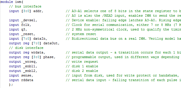
Mapping out the complete schematic of the Liron took a couple of days. It’s a single IWM (the famous Integrated Wozniak Machine), combined with a small number of standard 7400-series logic chips, and a ROM to hold the boot code. Writing Verilog code for the FPGA to duplicate the 7400 chips’ functions was easy. Creating a Verilog reimplementation of the IWM was harder, but with the aid of the IWM spec and a logic analyzer I got it done. By selecting a moderately roomy FPGA, I was able to incorporate the boot ROM functionality too, so no actual ROM chips are needed. The entire design boiled down to some 3.3V level converters and a single FPGA, with a bunch of connectors and passive components. I realized the design wasn’t limited to being a Liron clone, but could also probably be a Disk 5.25 or Disk 3.5 controller with just a change of firmware. Maybe even a UDC controller. Ooh, the possibilities!
Hardware
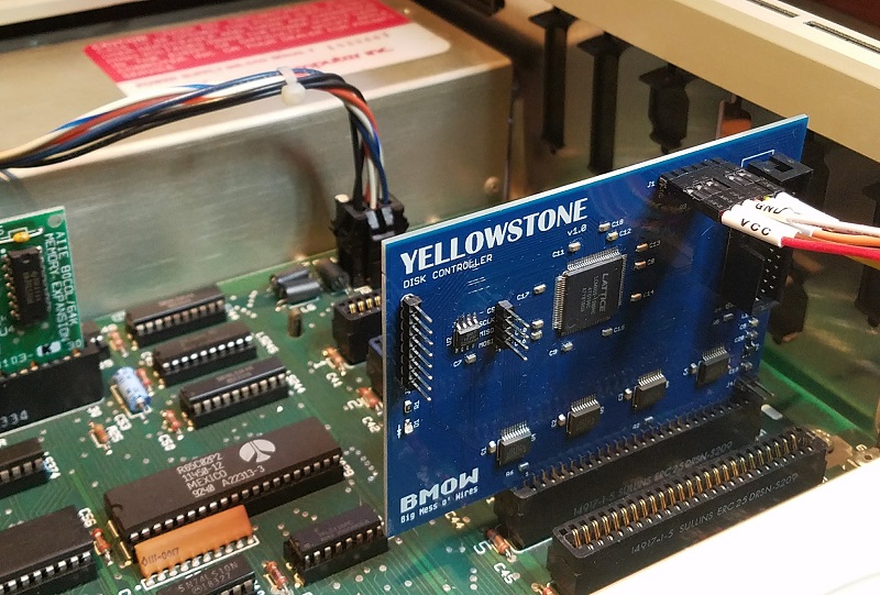
I worked like mad to finish the design in late July, just before a trip to Yellowstone National Park, which gave this project its codename. The core of the prototype board is a Lattice MachXO2 FPGA, specifically the LCMXO2-1200HC. This 100-pin bad boy has 1280 LUTs for implementing logic, and 8 KB of embedded block RAM to serve as the boot ROM or for other functions. It also has some nice features like a built-in PLL oscillator and integrated programmable pull-up and pull-down resistors. Unlike some FPGAs, the MachXO2 family also has built-in flash memory to store the FPGA configuration, so it doesn’t need to be reloaded from an external source at power-up. The FPGA can be programmed through a JTAG header on the card.
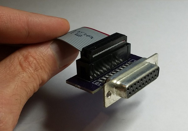
The external disk is connected to the card with a standard 20-pin ribbon cable, just like what you’d find inside an Apple IIc, or on the Floppy Emu. In fact for the Floppy Emu, you can connect a 20-pin ribbon cable directly from the Emu to the FPGA card, with no DB-19 required. For other external disk drives, I built a small adapter that converts a short length of 20-pin ribbon cable to a DB-19 female connector.
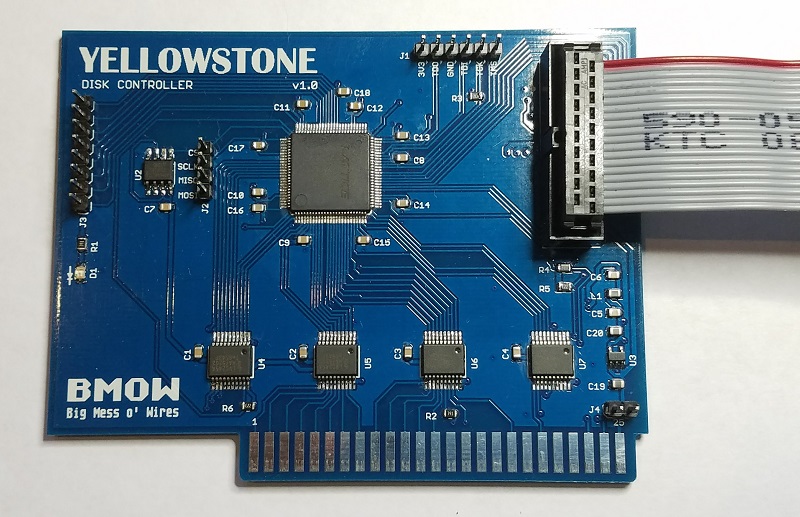
Because the FPGA’s maximum supported I/O voltage is 3.3V, but the Apple II has a 5V bus, some level conversion is needed. I used four 74LVC245 chips as bus drivers. These chips operate at 3.3V but are fully 5V tolerant, and the Apple II happily accepts their 3.3V output as a valid logic “high”. One of the chips operates bidirectionally on the data bus, and the others handle the unidirectional address bus and control signals.
There’s a tiny 3.3V voltage regular on the board, which you can see at the lower-right at U3. It’s barely any bigger than a 0805 size SMD capacitor. Even with these small components, I was still able to solder the entire prototype board myself by hand.
Just for grins I added a 2 MB serial EEPROM to the board, which you can see at U2. 2 MB is enough to store 14 disk images of 5.25 inch disks, or a single larger disk image. It’s not central to the design, but if it works then the card could function as an all-in-one virtual disk like the CFFA3000, in addition to functioning as a disk controller for external drives. More options!
Status
Here comes the embarrassing part. After July’s spurt of activity, the PCBs and parts arrived in the mail. And then I did…. nothing. Finally in October I assembled one prototype board, stuck it in my Apple IIe, and played with it for a bit. But since that day I’ve done…. nothing. I’m struggling with some internal dilemma about the balance between a hobby and a business, and doing things because I want to or because I think I should want to. I’m hoping that by publishing this summary, I may spur myself into further action.
The prototype board works as far as I’ve tested it, but that’s not very far. I verified that I can program the FPGA via JTAG, and that it responds to address and data on the Apple II bus, but that’s about it. I haven’t yet looked at what it’s doing on the external disk interface, or tried connecting a real drive. My attention has just been focused on other things, and even though I always mean to return to this project “soon”, somehow I never do.
There’s at least one serious bug with JTAG programming that needs to be addressed. When the board is outside the Apple IIe and powered from a separate 5V supply, JTAG programming works fine. But when the board is actually inserted in the IIe and powered from the slot, JTAG programming doesn’t work. It always fails with a communication error. I thought this might be some kind of noise or poor signal integrity on the JTAG traces when the board is in the IIe, but the traces are quite short and don’t cross any other signal traces that might carry interfering signals. I also thought maybe I had power problems, and the IIe’s 5V supply was drooping briefly when I tried to program the FPGA via JTAG. But as far as I can tell with a logic analyzer’s analog functions, the 5V and 3.3V supplies remain stable. It’s a mystery that will require some better tools and more careful testing.
Next Steps
What’s next for this FPGA disk controller, assuming I ever finish it? Will it become a new product in the BMOW store? That was certainly my original plan, although my lack of motivation these past months has cast some doubt on that idea. I want to keep fun hobbies fun, and not have them become an obligation and a chore, which I fear is already happening with the other retro computer gizmos I’ve developed in the past few years. We’ll see how it plays out.
Assuming this eventually becomes a new product, how will users reprogram the FPGA in order to clone a different type of disk controller? It’s not reasonable to expect that everyone will own a stand-alone JTAG programmer and know how to use it. Unfortunately I can’t see any alternative solution that wouldn’t require extra hardware and complexity, and push up the cost of the board. I might add a microcontroller and an SD card socket for loading alternate firmware, but that would be a fairly ridiculous amount of extra baggage if it were used only for JTAG. Perhaps the Apple II itself could be used as a JTAG programmer, with some extra hardware that optionally bridged the data bus to the JTAG interface? Sounds complicated, and it would leave the question of how to get the firmware onto the Apple II first. Or maybe the user could choose between a few different built-in firmwares using a switch, but would be unable to load new ones? That sounds more plausible, but would mean a bug in the firmware couldn’t be easily fixed.
Fortunately those questions can wait. The first priority is to finish debugging the prototype, connect it to some real disk drives, and verify that it works. Maybe by Christmas…
Read 38 comments and join the conversation