

Archive for the 'Backwoods Logger' Category
The Quest For A Simple Level Converter
Sometimes the simplest things give me the most trouble. I’ve been working on a downloader cable adapter for the Backwoods Logger, with the goal of supporting both 5V and 3.3V FTDI cables. Because the Backwoods Logger is a 3.3V design, the incoming TXD (transmit data) signal from a 5V cable needs to be lowered to 3.3V for safe operation. However, the incoming TXD signal from a 3.3V cable should be passed through unmodified. Outgoing signals from the Logger require no conversion, because a 3.3V output is still a valid logic “high” for a 5V system. I need a level converter for a single input, that operates correctly with both 5V and 3.3V inputs with no configuration or jumper settings.
Level Converter Chip
One solution is to use a 3.3V chip with 5V tolerant inputs, like a 74LVC244. That would work, but I’d prefer something simpler and smaller if possible, since I only have a single input to convert.
Clamp Diode
A second solution is to use a series resistor and a clamp diode, like this (image from daycounter.com):
![]()
That prevents the voltage at the 3.3V Backwoods Logger input from going more than a diode drop above the 3.3V supply. With a standard silicon diode’s drop of 0.6V, that clamps the voltage to 3.9V. For the ATmega328, that’s not safe: its maximum rated voltage on any input is just 0.5V about VCC. A germanium diode has a drop of 0.2 to 0.3V, so that would work, but it’s not a part that many people typically have handy in their parts bin.
This solution also has the drawbacks of consuming current from the 5V output, and dumping current into the 3.3V supply, raising the supply voltage. The FTDI outputs have a maximum output current of 24 mA. Assuming a germanium diode with a 0.2V drop, that means R1 needs to be at least 62.5 Ohms. Frankly I’m not sure how to quantify the risk of dumping current into the power supply. In the case of the Logger Classic with its tiny CR2032 battery, dumping 24 mA into the battery in the wrong direction definitely doesn’t sound good.
Zener Diode
The approach that appealed to me most was to use a series resistor and a Zener diode connected to ground, like this (image from daycounter.com):
![]()
The Zener has a known reverse-bias breakdown voltage called the Zener voltage. Raise the voltage above the Zener voltage, and the diode conducts. The series resistor produces a voltage drop, so that the voltage at the Backwoods Logger input never rises above the Zener voltage. You can get 3.0V or 3.3V Zeners (or lots of other values too).
So I ran out and bought some Zeners, and built this circuit, and it didn’t work at all how I’d expected it to. I used a 3.0V Zener, and a 100 Ohm series resistor, to limit the current drawn from the FTDI cable to 20 mA. When I connected a 5V dummy output, I got 2.91V at the Logger input. That seemed odd, it was off by 0.09V, but it was still close enough. Then I connected a 2.95V dummy input (the actual voltage from my crummy “3.3V” breadboard regulator), and I got 2.4V at the Logger input. Huh? That’s not going to work. I had expected that for any voltage below 3.0V the Zener would do nothing, and for anything above 3.0V it would clamp it to 3.0V, but that’s clearly not what happened.
What went wrong? Truthfully, I’m not exactly sure. The datasheets talk about a minimum current necessary to get the Zener effect, but I’m not sure that applies here. I can’t safely increase the current further anyway without damaging the FTDI cable. But would more current even solve this problem? It makes sense that the Zener wouldn’t really turn on instantaneously at 3.0V, but rather would begin to conduct more and more as the voltage approaches 3.0V. With a voltage of 2.95V, the Zener would already be partly conducting, pulling the voltage seen at the Logger input below 2.95V. But how much below? How can this be quantified?
One thing in particular bugs me about all the Zener diode datasheets: every datasheet lists values for standard measurements called Izt, Rzt, Izk, Rzk, Rz, and a few others. These are standard measures from some hypothetical standard Zener graph, but the datasheets never actually show this graph, and I’ve never been able to find one anywhere. I know “k” is for “knee” and I believe “t” is for “test”, but what I really need is an actual IV curve for a Zener with these values labeled. Then I think I’d understand this better.
Further Complications
Just to make things more interesting, there’s one more constraint to consider. The Logger Classic uses an unregulated battery as its supply. It can work just fine at battery voltages of 2.8V, and probably down to 2.5V or even lower. In order to stay within the VCC + 0.5V margin of the ATmega328P, the input voltage must not go more than half a volt above the potentially fading battery voltage. A standard 3.3V input when the battery is 2.7V would actually damage the ATmega. That’s why I chose to use a 3.0V Zener rather than a 3.3V one. That should be safe down to a battery voltage of 2.5V, below which I could configure the ATmega’s brownout detector to engage.
The Way Forward
I’m going to sleep on this, and see if anything brilliant comes to me. If anyone else has a suggestion, please reply in the comments. Assuming I can’t find a way to make the Zener work while still meeting the other constraints, then I’ll probably cave in and use a level converter chip. Without really understanding the implications of current flowing into the supply battery under the clamp diode method, I wouldn’t feel comfortable relying on that approach.
Read 19 comments and join the conversationBackwoods Logger – Open Source and On Sale
The Backwoods Logger is a programmable graphing altimeter / thermometer, developed and documented here at Big Mess o’ Wires. Today is a big day for the Logger: I’m re-launching it as a formal open hardware project, and also offering a small test run of pre-assembled Backwoods Logger Mini units for sale. After corresponding with many enthusiastic people over the past months, I’m convinced there’s a community of Logger-heads out there that’s bigger than just me. My goal is to bring together people who are merely curious about the Backwoods Logger, or are interested in buying a prebuilt Logger, or have already built their own Logger, or are interested in making improvements to the existing Logger software and hardware.
Re-launching the Backwoods Logger as an open hardware project means it will no longer be a personal endeavor developed solely by me, but a collobarative effort that welcomes involvment from everyone. The project is hosted at Google Code: check out the new Backwoods Logger project page. All the source code, schematics, and other design files are there. And if you’re interested, please consider joining the project.
I’ve also created a Backwoods Logger discussion mailing list, intended for questions, ideas, or any other conversation about the Logger. The list is public and is hosted by Google Groups, and you can join or leave the list at any time via the group settings page. Membership in the discussion list is separate from membership in the Google Code project, and everyone’s welcome to join the mailing list regardless of whether they’re project developers or just curious about what’s happening in Logger Land.
Backwoods Logger Mini Sale
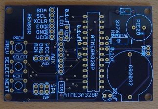
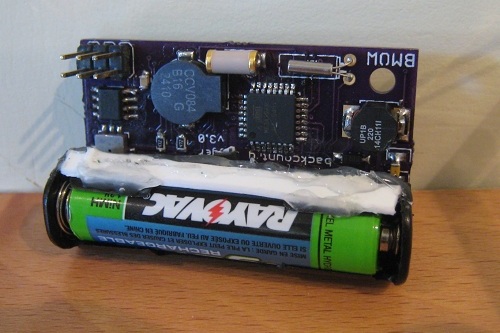
![]()

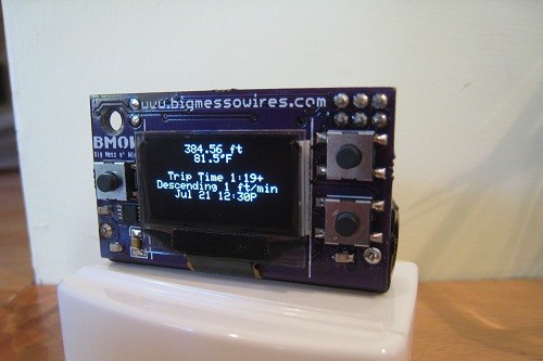
To help kick things off, I’ll be selling a small test run of pre-assembled Backwoods Logger Mini units. The Mini is the OLED version of the Logger, pictured above.
- Temperature measurements in 0.5 degree steps, from -10F to 117.5F
- Air pressure measurements in 0.01 in-Hg steps, from 5.9 to 36.12 in-Hg
- Altitude (calculated from air pressure) measurements in 2 ft steps, from -1384 ft to 14999 ft
- Can configure metric Loggers with units in degrees C, millibars, and meters on request (ask when ordering)
- Graphs of temperature, pressure, and altitude over time
- Three graph time scales: past 2 hours, past 10 hours, past 2.5 days
- Current rate of ascent/descent
- Estimated time of arrival at a user-defined altitude
- Weather forecast
- Station pressure and pressure at sea level
- Snapshot feature – make a permanent record of date, time, altitude, temperature, and pressure at important waypoints
- Current date and time display
- Battery voltage indicator
- Sound on/off control
- 128 x 64 OLED screen
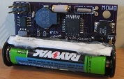
- Battery Life: 3 – 5 months with a single AAA battery
- Dimensions: 1.9 x 1.1 x 0.7 inches (48 x 28 x 17 mm)
- Weight: 0.7 ounces (19g), including battery
Also check out this Backwoods Logger demo video to see a demonstration of the Logger’s features. The video shows a Logger Classic, which has a lower-resolution screen and is slightly bigger and heavier than the Mini, but otherwise has an identical set of features. Don’t see a feature you want? Join the project, and help create it.
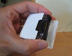
The hole in the corner of the Mini board can be used to tie it to your backpack, or wear it around your neck on a lanyard. The Mini has no case, so if you expect wet weather you’ll need to provide your own. The last photo above shows a Mini inside a dental floss container!
The price for this test run will probably be about $59, but will depend on how many confirmed orders I receive beforehand. You should understand these will be prototype units, and may contain bugs or other defects, but I’ll do my utmost to resolve any problems that might occur. If you’re interested in purchasing a Backwoods Logger Mini, please contact me and let me know. I expect the lead time to be about six weeks.
Read 9 comments and join the conversationBackcountry Logger Mini Custom Build
Chris Stemple has finished the first custom build of a BMOW project by a reader, with a great-looking build of the Backcountry Logger Mini. Using some spare room on a panel from InternationalCircuits.com, Chris added and removed a few things from the original layout. His board features solder points for additional microcontroller pins, as well as a power switch and LED, while eliminating the external EEPROM chip. The build went smoothly except for some difficulty soldering the BMP085 sensor, which took the application of a heat gun to snap into place. Awesome work!
If you’re interesting in building a BMOW project, you’ll find all the design files and schematics on the summary page, listed under the Project Summaries header in the left margin.
Be the first to comment!Backcountry Logger Free PCBs
The Backcountry Logger is a portable device for measuring and graphing altitude, temperature, and air pressure. It should appeal to any outdoorsy people interested in examining altitude, temperature, or pressure movements over timescales from an hour to two weeks. That includes hikers, climbers, skiers, trail runners, cyclists, kayakers, snowmobilers, horseback riders, and probably many others. The development of the Backcountry Logger has been discussed here in detail over the past few months.
Today I’m publishing the whole Backcountry Logger design under the Creative Commons license (CC BY-NC-SA 3.0). My hope is that others will build their own Backcountry Loggers, take them on trips and experiment with them, then make firmware or hardware improvements and share them back. I would love to see a community of user/developers emerge to make future Backcountry Logger versions even more awesome than anything I’ve yet imagined.
This Backcountry Logger file distribution contains all the firmware source code, schematics, board layouts, Gerbers, parts lists, and everything else you’ll need. You can build a copy of the Logger Classic or Logger Mini, or design your own version by modifying the hardware and firmware to meet your needs. If you make some improvements you’d like to share, send them to me and I’ll post them here. If there’s enough interest, I’ll make a project at Sourceforge or another site so people can collaborate on further Backcountry Logger development.
The total parts cost for either version of the Backcountry Logger is about $40. The Logger Classic can be assembled in an hour or two, and is fairly easy to build. The Logger Mini is more challenging to build, due to the use of surface-mount parts, but the result is a much more compact and professional-looking device. You can also build the Backcountry Logger on a breadboard, following the Logger Classic schematics.
PCBs can be made using the Gerbers included in the file distribution, but to kick things off, I’m giving away some free PCBs for the Logger Classic and Logger Mini to those who are seriously interested in experimenting with it. Send me email and let me know what you plan to do with it, and if I like your story I’ll send you a PCB.
For the curious, the README from the file distribution is included here:
Copyright (c) 2011 Stephen Chamberlin. All rights reserved.
Backcountry Logger by Stephen Chamberlin is licensed under a
Creative Commons Attribution-NonCommercial-ShareAlike 3.0 Unported License. (CC BY-NC-SA 3.0)
The terms of the license may be viewed at http://creativecommons.org/licenses/by-nc-sa/3.0/
Based on a work at www.bigmessowires.com.
Permissions beyond the scope of this license may be available at www.bigmessowires.com.
BUILDING YOUR BACKCOUNTRY LOGGER
1. Buy the required parts. The total cost should be about $40 USD. The parts required depend on which version of the logger you want to
build. See partlist.txt for the list of required parts.
2. Make or buy the circuit board (PCB), or prepare a breadboard. Visit www.bigmessowires.com and ask if I have any extra boards left. If
not, send the included Gerber files to a PCB prototyping service, and they can manufacture a board for about $25. If you are building the
logger on a breadboard instead of a PCB, follow the instructions for the Logger Classic.
3. Assemble the board. The Logger Classic uses all through-hole parts, and can be assembled in an hour or two. The Logger Mini uses all
surface-mount parts, and is more challenging to assemble, but can still be assembled by hand (I did it!).
Logger Classic:
The BMP085 breakout board comes without the header attached, so you must solder your own header to it. Solder male header to the *same*
side as the BMP085 chip. When you later mount the breakout board onto the socket on the main board, it should be upside down, with the
BMP085 on the underside, hidden from view.
Logger Mini:
The SQ-SEN-200 vibration sensor can be omitted. This part is only available directly from Signal Quest, with a minimum order quanity of
20. If omitted, the trip timer feature will not work.
The schematic and board layout show an external EEPROM chip. This was originally intended to store longer-term or higher-resolution
altitude/temperature data, but the firmware doesn’t use it. It can be omitted.
The bare BMP085 chip is difficult to hand-solder, because the pins are on its bottom, inaccessable with a soldering iron. To solder it,
first tin all 8 pads on the PCB with a small amount of solder. Make sure the heights of the solder blobs are as even as possible from pad
to pad. Next, apply flux to the BMP085 pins, and place it in position on top of the tinned pads. While pushing down on the chip from above
with a pick, heat the exposed portion of each PCB pad, one at a time, until the solder melts. The heat will be conducted along the pad,
under the chip, and the molten solder will bond to the hidden BMP085 pin. You may need to repeat this procedure several times to get a good
solder connection.
There may be a clearance problem between the battery holder and a few of the surface-mount components closest to it. If necessary, cut
away a small portion of the battery holder plastic with a knife to make it fit. Do not cut away any more plastic than necessary, or the
battery holder may bend when a battery is inserted.
4. Get an AVR programmer. I use the AVRISP mkII, which is $35 from Digi-Key. The $22 USBtinyISP AVR programmer is another popular choice:
see http://www.adafruit.com/products/46
5. Install the battery.
6. Connect the programmer to the board’s ISP header. Run AVR Studio, avrdude, or other AVR programming software. Confirm that the board is
working electrically, but connecting to the AVR and reading the device ID.
7. Program the AVR with the Backcountry Logger firmware. Use the programming software to load the .hex file into the AVR’s Flash memory.
You can use the precompiled hikea.hex file, or compile the included C source files and make your own .hex file.
8. Set the EESAVE fuse on to prevent your altitude/temperature data from being erased every time you reprogram the AVR.
MODIFYING THE LOGGER
You are encouraged to experiment with changes to the Backcountry Logger software and hardware. If you make a change that you want to share,
please send it to me and I’ll include it in a new version of this distribution. If there is enough interest, I will make a project at
Sourceforge or a similar site, so people can collaborate on further Backcountry Logger development.
Some ideas for further development:
- Add more detailed analysis tools to the software. Rate of ascent graphs, day by day statistics comparisons, user-defined graph
timescales, etc. - Add a way to download the stored sample data to your PC.
- Preload the elevation profile of your expected route onto the logger before starting a trip, then compare measured altitude samples with
the preloaded profile to determine where you are. - Modify the Logger Mini software to make use of the external EEPROM, to store a longer sample history, or high-resolution samples.
- Make a version of the Logger Classic that uses the higher-resolution OLED found on the Mini. These OLED’s can be purchased on a breakout
board on eBay or from Adafruit: http://www.adafruit.com/products/326
COMPILING THE SOFTWARE
The Backcountry Logger source code was built with AVR Studio 5, and the hikea.avrgccproj file will only work with AVR Studio 5. If you are
using a different version of AVR Studio, or a different compiler entirely, you will need to create your own project file or makefile with
the following settings:
Logger Classic
define these symbols: LOGGER_CLASSIC, NOKIA_LCD, F_CPU=1000000
include these libraries: libm.a
change these fuses: EESAVE on. Fuse settings are low: 0x62, high: 0xD1, extended: 0xFF
Logger Mini
define these symbols: LOGGER_MINI, SSD1306_LCD, F_CPU=8000000, SHAKE_SENSOR (optional)
include these libraries: libm.a
change these fuses: EESAVE on, CKDIV8 off. Fuse settings are low: 0xE2, high: 0xD1, extended: 0xFF
Logger on a breadboard:
follow the instructions for Logger Classic.
If you want to use the original software as-is without compiling, you can also use the precompiled hikea.hex files in the Classic or Mini
subdirectories.
USING THE SCHEMATIC AND BOARD LAYOUT
The Eagle .sch and .brd files can be found in the Classic and Mini subdirectories. In addition to the standard Eagle libraries, you will
also need the SparkFun library, Adafruit library, and Big Mess o Wires library. The Sparkfun and Adafruit libraries can be downloaded from
their respective web sites.
https://github.com/sparkfun/SparkFun-Eagle-Library
http://www.ladyada.net/library/pcb/eaglelibrary.html
The BMOW library is included here, as big-mess-o-wires.lbr.
PIEZO BUZZER NOTE: The Logger Classic uses a Murata PKM13EPYH4002 piezo buzzer, which has a 5mm pin spacing. I was foolish and added a new
5mm piezo footprint to the Sparkfun library. Your version of the Sparkfun library will not have this footprint, so you will get an error
when opening the schematic of layout file. If you wish to use this same buzzer, you can find the appropriate part in the big-mess-o-wires
library, named PIEZO.
Logger Mini on the John Muir Trail
Logger Mini and I returned this week from the John Muir Trail. It was an amazing, epic trip, ending unexpectedly with me stranded in the middle of nowhere in the Owens Valley desert, gawking at the PLAGUE WARNING signs. It took me two days to get out, but I’m back home now and plague-free.
I used the logger quite a lot during the trip, and it worked like a champ. After a couple weeks of real-world use on the trail, a few points become clear:
- The trip timer feature (using a vibration sensor to detect movement) was totally pointless. It worked fairly well, but didn’t add anything of value, and I never used it even once. I’ll delete it and the associated hardware from future designs.
- Graphs going back more than 12 hours were also pointless. I never looked at them. That’s great, because it takes a lot of memory to store the sample data further in the past. I’ll delete the extra external EEPROM from future designs.
- Temperature measurement worked great for determining overnight lows, but not so great for highs or current daytime temperature. Inside its case, or in my pocket, or in the sun, it almost always showed a temperature that seemed unrealistically high. Maybe replace the minute-by-minute temperature graphs with daily high/low/avg stats instead.
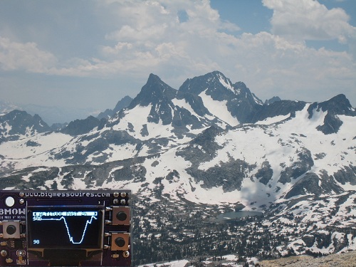
- Where the logger really shone was the display of current and recent altitude. When we knew we were climbing towards a 12100 ft pass, and had been going for what seemed like hours, it was cool to pull out the logger and see exactly where we were and how much climbing was left.
- The screen was difficult to read in direct sunlight, where difficult means “impossible”. I knew this already, but it was still annoying.
- Reliability was excellent. I never experienced a single problem or unexplained reset on the trail.
- Battery life was excellent. My prototype is still on its original AAA battery, and the battery voltage has barely changed since I first installed it.
- There’s definitely a place for the logger, even in a GPS world. I also had a GPS along, but the logger is 20% of its size and 10% of its weight. The GPS chewed through batteries, had difficulty getting an accurate position fix, and exhibited poor alitutude accuracy even when it had a fix.
Overall, bringing along the logger was a clear success. So, what next? My inclination at this point is to share all the hardware and software design data, and try to get some additional people interested in improving the design further. I think there’s a place for both the Logger Mini and Logger Classic. The Classic is all through-hole parts and can be assembled in about an hour. The Mini is smaller and cooler, but more challenging to assemble. While the underlying hardware is different, the programming model is nearly identical, and the same software can be compiled for either device with only a few device-specific sections to reflect the different display screens. I have a few more unpopulated PCBs of both types that I can offer to developers, or put the Eagle and Gerber files somewhere and let people do what they like with them. Anyone have any other specific suggestions? It would be great to see this grow into something big.
Read 3 comments and join the conversation
Logger Mini Refinements
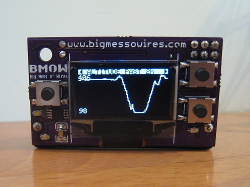
![]()
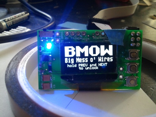
I’ve made some refinements to the Backcountry Logger firmware, based on my experiences in the field last weekend. I’ve decided to bring the Logger Mini with me on my upcoming John Muir Trail trip, rather than the Logger Classic that I brought to Mount Langley. The Mini (shown here) is smaller, lighter, and has a higher-resolution screen than the Classic. Earlier I was concerned about the durability of the Mini, but I constructed a fairly rugged carrying case for it out of a dental floss container!
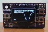
The biggest problem I had on the Langley trip was accidental button pushing while the logger was in my pocket. The first photo shows my solution to this problem: both the PREVIOUS and NEXT buttons (but not SELECT) must be held in order to unlock the device when awakened from sleep mode. I also got fancy and threw the BMOW logo onto the unlock screen for fun. So far this approach to unlocking seems to have conquered the random button pushing problem nicely.
The extra resolution of the Mini’s 128 x 64 displays really helps the graphs — they look much cleaner than with the Classic. I boosted the OLED display brightness to the maximum, but unfortunately it still looks washed-out when viewed in direct sunlight.
The Mini has a SQ-SEN-200 omnidirectional tilt/vibration sensor, which the firmware uses to detect movement. If there’s movement for four consecutive minutes, it concludes you’ve begun a trip, and starts the trip timer. After 6 consecutive minutes with no movement, the trip timer stops. In practice the movement detection with the SQ-SEN-200 works very well, but the time thresholds may need to be tweaked. The 1:19 trip shown here was my walk down the hill to the store and back.
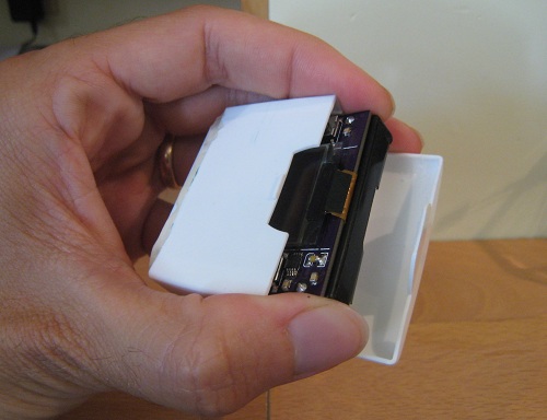
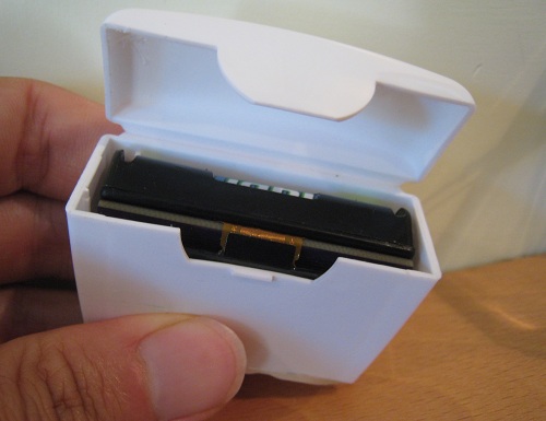
To protect the Mini, I built a storage case out of an old dental floss container. I cut off the lower half of the container to reduce its height, and then hot-glued a plastic scrap over the bottom opening to seal it. The resulting case is very sturdy, and fits the Mini perfectly.
The firmware now almost completely fills both the program and data memories on the ATmega, which I think is my clue that development is done. Save for possible bug-fixes, then, any further Backcountry Logger development will focus on hardware improvements such as different displays or batteries, and simplifications and cost-reductions of the circuitry.
Read 2 comments and join the conversation