

Archive for the 'USB Wombat' Category
USB-to-ADB is not Dead
Long-time readers of this blog may remember a USB-to-ADB converter project that never made it past the concept stage. I wrote a series of posts about it last year, and made some decent progress with ADB emulation and USB host support. I ordered parts to build a second-generation prototype, but when they arrived, I let them sit on my desk collecting dust for 12 months. Until today.
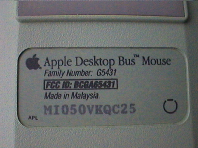
The goal is to build a simple and reliable device for using modern USB peripherals with a vintage Macintosh or Apple IIgs computer. These classic machines normally use ADB peripherals, the Apple Desktop Bus. Last year I called this project “USB-to-ADB”, but that seemed to confuse many people into thinking it was for using ADB keyboards on a modern computer. In the hope of avoiding confusion, I’ve tentatively decided to rename this effort “Retro USB”. I welcome suggestions for better and less ambiguous names, especially names that somehow suggest a Mac and Apple II tie-in.
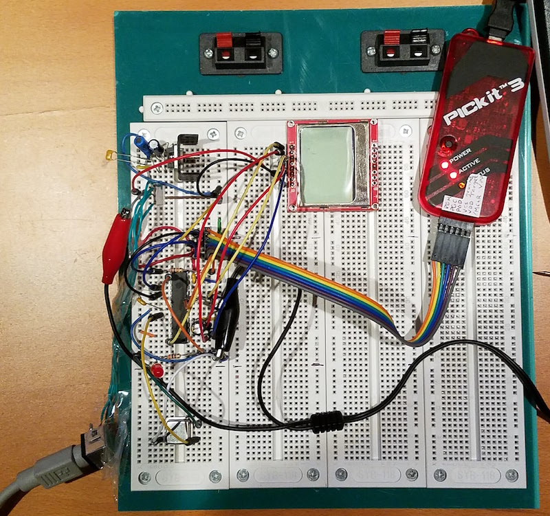
Today’s effort was about catching up to where I’d been a year ago. Using a breadboard and a bare PIC32MX230F256B, I assembled something more-or-less equivalent to the PIC32 USB Starter Kit board I’d used previously, and got it working. I also added an LCD screen for displaying diagnostic messages. Nothing terribly exciting yet, but it took me quite a long time just to get the PIC software installed, and learn how to wire up everything by hand for an LED blinker example.
PICs don’t seem to get much love in the hobby electronics world, so for those who didn’t read last year’s project posts, I’ll remind you how I ended up selecting the PIC32MX. To convert a USB keyboard and mouse to ADB, I need a microcontroller with USB Host support (uncommon, most only have USB Device support) and the ability to work with a USB hub, so a keyboard and mouse can be used simultaneously. This second requirement proved to be the more difficult one to meet, and the PIC32 series was the only one I found that had published sample code for accessing multiple USB devices through a HUB. In theory any microcontroller with USB Host could do it, since it’s “just software”, but I’m not interested in going deep into the bowels of writing my own USB stack.
I ran into a minor problem with the crystal oscillator. My example program worked fine with the PIC’s internal RC oscillator, but I couldn’t get it to work reliably with an external crystal and capacitors, as shown in the data sheet. It sort of worked sometimes, but was very flakey. I know crystal oscillator circuits are very sensitive to stray capacitance, and my breadboard circuits with their long component leads and loopy wires everywhere were probably too problematic. When I replaced the crystal circuit with an external clock in a can-type package, running at the same speed, it worked fine. I’m 95% sure this was just a breadboard problem, and if I reproduce the same crystal circuit on a well-designed PCB it will work fine.
It shouldn’t take me much longer to finish restoring the functionality I had with the old prototype, then I can finally begin the long-delayed work of stitching together the USB and ADB pieces of this project.
Read 5 comments and join the conversationMore USB-to-ADB Planning
This must be a record for the number of times I’ve posted about a project, without actually building the project, or even a half-way working prototype. I’m still fleshing out my ideas for a USB-to-ADB keyboard/mouse adapter for vintage Macintosh and Apple IIgs computers. In my last update, I described how USB interrupts would interfere with the software timing loops in my bit-banged ADB implementation, and sketched out a few possible solutions to the problem.
After more thought and research, I’ve decided to try the approach that my last post called “timer hacking”. It isn’t really a hack, but rather a better (but more complex) implementation of ADB for the microcontroller. It means removing all the blocking code and software delay loops from my initial ADB implementation, and replacing them with interrupts driven from timers and pin state change events. The ADB-related interrupts will be given higher priority than USB interrupts, and can even interrupt the USB interrupt handler. Because this new ADB code will be interrupt driven, using hardware timers, simultaneous USB activity shouldn’t cause any timing errors. I’m reasonably confident this should all work, but it’ll take time to implement.
I discovered that the PIC32MX I’m using has an input capture feature with a 4-deep FIFO. That will be much nicer than using a basic pin state change interrupt, because input capture records a timer value at the instant a pin changes state, instead of sometime later when the interrupt handler runs and executes code to query the current timer value. So timing measurements when reading ADB will be more accurate. The FIFO means the ADB interrupt handler will only need to be invoked after every 4 rising/falling edges on the ADB signal, instead of for every edge, which will help make things a little more efficient. For writing ADB, I’ll look at using the microcontroller’s built-in PWM hardware, changing the pulse width for each ADB bit, which should be slightly more efficient than using a simple hardware timer to toggle the ADB pin.
Taking a Break
Unfortunately, I can’t actually pursue this plan yet, with the PIC32MX USB Starter Kit II that I’ve been using. This kit has virtually none of the PIC’s pins broken out onto headers, essentially no I/O at all except for the USB ports. Earlier I managed to hack in a single external input by soldering a wire to an unused crystal footprint on the board, which was enough for some simple experiments. But that particular pin isn’t connected to the PIC32MX’s input capture peripheral. Some PIC32MX’s have the ability to dynamically remap the pins, but not this particular one. So in short, I can’t use input capture with this hardware.
Even if that weren’t the case, there are other reasons I want access to more I/O pins. It would be a huge help with debugging if I could connect a serial terminal to the PIC’s UART, and log messages with it. While there’s already a built-in debug-print capability that operates over USB, it seems incredibly slow, on the order of 100 characters per second. And I’d also like additional I/O to experiment with some of this device’s other planned features, like a power-on button connected to ADB’s “on” pin. I’d also like to start testing with the actual model of PIC32MX I plan to use in the final device, instead of the high-end PIC32MX795 in the USB Starter Kit. So it’s time for me to order a bunch of discrete parts, or maybe some much simpler PIC32MX prototyping board, and get working on a real prototype.
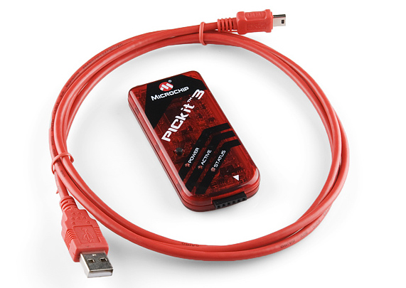
The trouble comes when I need to program the PIC32MX on this new board or prototype. Many are designed to be programmed via USB, but I can’t do that if the USB interface is already in use as a USB host. The USB Starter Kit II works around that problem by having two separate PICs, each with their own USB interface, but that’s complex and expensive. The other solution is to use a programmer like a PICkit 3 to program the chip via its ICSP pins, so that’s what I’ll do. Except I don’t own a PICkit 3. I ordered a PICkit 3 clone a while ago from Aliexpress, but it probably won’t arrive for several weeks. Until that happens, I’ll be taking a break from this project, aside from possible further sketching out of ideas on paper.
Read 11 comments and join the conversationUSB to ADB – Multitasking Two Interfaces
It’s time for a new progress report on my USB to ADB converter project! My goal is to design a simple PIC32 device that enables USB keyboards and mice to be used with vintage ADB-based Macintosh and Apple IIgs computers. You can read my earlier reports here: 1, 2, 3, 4, and 5. I don’t know when I’ve ever spent so much time investigating the feasibility of a project, without actually doing the project. Hopefully all this preparation will pay off.
Good news: I spent some time plowing through the details of Microchip’s USB library, as well as Suwa Koubou’s modified version, and things are beginning to make much more sense. Hosting a “simple” USB HID device like a mouse or keyboard is proving to be much more complex than I imagined, once you factor in all the behind the scenes work that would normally be handled by an OS or driver code. While I certainly don’t understand it all, I can say I understand the basic framework now. That should make life much easier as I go forward.
Bad news: the Microchip PIC32 tools and libraries continue to disappoint. On top of my previous complaints, I’ll add the poor quality of the Microchip USB stack source code. It looks like something that was hacked together by a team of student interns over a period of years. It’s a confusing and messy overall structure, with heavy use of #defines for function names, many lines commented out, comments that says useless things like “HHHHHHHHHHH”, hard-coded assumptions, debug print messages… not good. Maybe I’m looking at the wrong code? It definitely doesn’t feel like a professional-quality software library you can rely on for a real product.
More bad news: I’ve also discovered that the MPLAB X debugger is flaky. It will often stop in the middle of a debugging session and report “user program finished”, even when I can tell the program is actually still running. And I found that if you set a breakpoint while the program is running, it won’t necessarily work. You have to pause the program, set the breakpoint, and then resume. I only discovered that by accident in a moment of frustration.
The urge to throw the PIC in the trash and start over with something like the SAMD21 is growing, but I still haven’t done it. I keep rationalizing that I’ve already come this far…
Multitasking ADB and USB
The major bad news relates to servicing the ADB and USB interfaces simultaneously. I wrote about this concern previously: if USB-related interrupts happen too often and take too long to service, they may interfere with the software-derived timing of my bit-banged ADB interface. I did some earlier tests by setting breakpoints inside the USB interrupt handler, and determined that interrupts are only used for USB device attach and detach events. So my concern was unfounded… or so it seemed. In reality I was bitten by the breakpoint bug that I only recently discovered, and the USB interrupt actually fires at least once every millisecond, plus additional times when transfers are completed. Doh!
I thought I might still be OK if the USB interrupt handler was very short, so its impact on ADB timing would be minimal. ADB data is encoded at 1 bit per 100 microseconds, and given its encoding method, a timing error of up to 10-15 us could probably be tolerated without causing errors. Using the PIC32’s built-in core timer, I was able to measure the typical and worst case execution times of the USB interrupt handler, and it was about 50 microseconds at 80 MHz with code compiled using -O1 optimization. That’s definitely too slow to avoid causing ADB timing problems. What’s worse, for the final device I’d planned to use a cheaper version of the PIC32 that only runs at 40 MHz, so the interrupt handler time would actually be 100 microseconds.
So it seems that naively combining a USB keyboard/mouse example with my bit-banged ADB implementation is not going to work. What are my alternatives?
UART Hacking
If there were a hardware ADB peripheral on the PIC32, then there would be no problem. ADB bytes could be read in/out of a buffer by the hardware peripheral in parallel with USB activity or other unrelated code, and then handled later in the main loop via polling, or via an ADB interrupt. Of course there is no ADB peripheral, but maybe the UART could be abused to do the job? ADB is sort of like serial communication, in that there’s no independent clock, and it runs at a fixed bit rate. But it’s unlike serial in the way bits are encoded. Instead of a simple high voltage for logical 1 and low voltage for logical zero, ADB encodes every bit as a pulse whose width determines its logical value. There are also some non-data signalling elements in a typical ADB transmission. But maybe I could run the UART at like 10x the actual ADB data rate, and capture the oversampled ADB waveform in a buffer for later analysis through software.
I think this UART hacking idea might almost work, except that serial communication always involves a start bit, at a minimum. It’s how the UART knows that a new byte has begun, but ADB communication doesn’t include a start bit. That would likely cause weird problems when reading and writing UART-as-ADB data. Maybe this could be overcome… I’ll need to think about it more. Unfortunately my PIC32 dev board doesn’t have the UART pins broken out to a header, or to anywhere I can solder, so I’d need to get new hardware if I want to try this route.
SPI Hacking
If the UART peripheral can’t do the job, maybe the SPI peripheral can? SPI uses an explicit clock signal, which ADB lacks, so that’s obviously a problem. But there’s no framing or start bits to worry about, which is good for the kind of hackery I’m envisioning. If the microcontroller were configured as SPI host, then it would wiggle the clock line for SPI reads and writes, but I could leave that signal unconnected and ignored. It’s so crazy, it just might work. But again, my PIC32 dev board doesn’t have the SPI pins broken out anywhere, so I’d need new hardware to explore this.
One point I’ve glossed over with both the UART and SPI hacking ideas is that ADB is an open collector bus. The host and devices pull it low when needed, but never actively drive it high. Instead, there’s a pull-up resistor to do that job. I’d need to include some extra circuitry to adapt UART or SPI traffic to an open collector bus.
Timer Hacking
Another approach would be to replace my software-derived ADB timing with hardware timers and pin state change interrupts. For reading ADB traffic, instead of polling in a tight loop in order to measure the widths of pulses on the ADB bus, I would use a pin state change interrupt and then determine the pulse width by checking a timer value in the interrupt handler. For writing ADB traffic, I would use hardware timer interrupts to change the ADB bus value at appropriate intervals. That would eliminate busy loops, and enable the USB and ADB communication to happen in parallel to some extent.
This would only work if the ADB pin state change and timer interrupts had higher priority than the USB interrupt, else USB interrupts would still introduce ADB timing errors. And this approach might possibly introduce USB timing errors, if the USB interrupt handler were delayed from executing by one of the ADB-related interrupts. Another concern is the latency for context switching and entering the ISR handler, after a pin state change occurs. This would need to happen quickly, even if the USB interrupt handler had been in the middle of executing, in order for ADB timing measurements to be correct.
Two Microcontrollers
My final idea is to use two wholly independent microcontrollers: one for ADB and one for USB. They would communicate with each other using SPI or another method supported with a hardware peripheral. That would probably work, but wouldn’t exactly be simple, as now I would have two different microcontrollers each managing two different interfaces in parallel. It would also increase the cost and complexity of the board, and make firmware updates more difficult. But it still might be a reasonable solution overall.
To be honest, I don’t love any of these ideas. I’m sitting on my hands for now, hoping that a better approach will jump into my mind. Here’s hoping! 🙂
Read 30 comments and join the conversationUSB to ADB Progress – Good News and Bad News
I’m still chugging away slowly on this USB to ADB input translator concept, using a PIC32 starter kit. First the good news: the ADB end of things is pretty much finished. I’ve designed a demo that creates a phantom mouse on a Mac SE, and when I hold a button on the starter kit, it moves the mouse around in lazy circles. It also coexists happily with other real ADB peripherals, remapping itself if necessary to avoid ADB address conflicts, and asserting the SRQ signal as necessary when it needs attention to report new mouse movement data. So that part is looking good.
Now for the bad news: the USB side is looking to be much more difficult than I expected. I’m struggling to create even a simple demo of reading from a USB mouse, let alone dealing properly with keyboards or USB hubs. Microchip only provides a single USB Host example project for the starter kit, which writes a file to an attached USB storage device. It works, but it doesn’t tell me much about how to handle a mouse or keyboard, and all of the USB specifics are in a separate pre-compiled library.
My search for a simple USB example is made harder by the fact that most PIC example code was designed for older Microchip compilers, and needs modification to get it working with the latest XC32 and MPLAB X. I found this example by Suwa-Koubou, who modified Microchip’s USB library to add support for multiple, cascadable hubs. It includes a simple example program that displays messages when USB devices are attached and detached, as well as examples of dumping input data from a mouse, keyboard, and joystick. Sounds great! But it was designed for the older MPLAB 8 and C32 compiler.
I spent a few hours trying to update and port this example project, but I ran into several problems while trying to update it. Something about the interrupt declaration mechanism has changed (shadow registers?), and it was designed for a different model of PIC32. I updated the code as I thought was needed, but the modified example doesn’t work. It never logs any attach/detach events, and doesn’t really do anything at all, except once when it crashed after I attached a USB keyboard. So more work is needed there.
Assuming I can eventually get the code working for reading from a USB mouse and keyboard, through a hub, I’m still worried about how to multitask the USB and ADB interfaces. My understanding of the USB Host implementation is shaky, but I think some events are handled by interrupts, while other activity requires periodically calling USBTasks() from the main loop, every 1 ms or so. Both of those present potential problems for the ADB interface, which bit-bangs the ADB protocol using a purely software-based implementation. ADB transactions can take about 3 ms, plus a few milliseconds more waiting for an attention or reset signal. If I don’t call USBTasks() during that period, it may starve the USB Host controller and cause errors. But if I insert periodic calls to USBTasks() inside the ADB code, it may cause ADB timing errors depending on how longUSBTasks() takes to return. Similarly, if a USB interrupt fires in the middle of an ADB transaction, and it takes more than a few microseconds to complete, it may cause timing errors for any ADB transaction that was in progress. Hmm…
Read 14 comments and join the conversationUnderstanding the ADB Service Request Signal
In the comments section of yesterday’s post, I mentioned a concern about ADB’s service request (SRQ) mechanism. A device requesting service can pull the ADB bus low at a certain point midway through another ADB transaction, which is called an SRQ signal. It appeared that the SRQ would interrupt the transaction in progress, and cause the host to poll other ADB devices to find the one asserting SRQ. The traffic logs collected by my ADB packet sniffer matched this theory. That would create the potential for bus deadlock if two devices both requested service, each one forever interrupting the other.
To answer this question, I got out my Saleae logic analyzer, so I could directly inspect traffic on the ADB bus. Here’s what I saw for a typical ADB transaction without an SRQ signal:
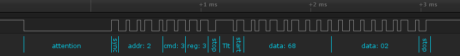
Everything up to the first stop bit is generated by the host. Everything after that is the reply from the device. Tlt is the “stop bit to start bit time” described in the ADB spec, a period of about 200 microseconds between the command and data sections during which the bus remains high.
A device asserts the SRQ signal by pulling the bus low during the first stop bit, after the command section of the transaction. I had thought this cancelled the rest of the transaction. Or maybe the SRQ signal (nominally 300 microseconds) ate into the Tlt time following it, but the rest of the transaction still finished, as shown by the dotted red line here:

My ADB traffic sniffer showed no traffic after the SRQ, so I assumed it cancelled the rest of the transaction. But when the logic analyzer captured a transaction including an SRQ, it showed this:
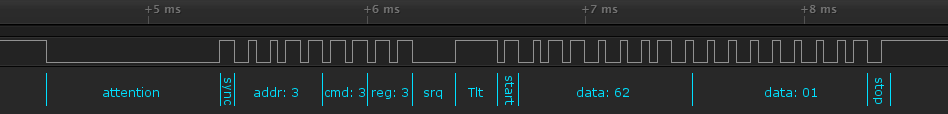
SRQ doesn’t cancel the transaction, nor does it eat into the Tlt time. It’s basically a stop bit with an extra-long low time, and it simply delays everything that follows. So there’s no fear of ADB bus deadlock.
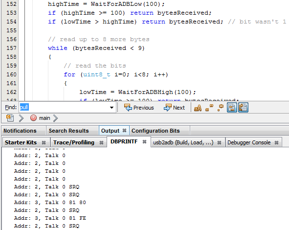
Why wasn’t my ADB traffic sniffer showing the data that follows the SRQ? It turned out this was wholly unrelated to my misunderstanding of the SRQ mechanism, but was just a bug in my code. I got too fancy trying to maintain a byte count and a separate SRQ flag in a single status byte, using bit masking operations, and my code didn’t work. With the bug fixed, I now see the true ADB traffic. Address 2 is the keyboard, 3 is the mouse. The keyboard keeps asserting SRQ, but that doesn’t prevent communication with the mouse.
ADB Reset
Addr: 0, Talk 3
Addr: 1, Talk 3
Addr: 2, Talk 3 62 02
Addr: 3, Talk 3 SRQ 69 01
Addr: 4, Talk 3 SRQ
Addr: 5, Talk 3 SRQ
Addr: 6, Talk 3 SRQ
Addr: 7, Talk 3 SRQ
Addr: 8, Talk 3 SRQ
Addr: 9, Talk 3 SRQ
Addr: A, Talk 3 SRQ
Addr: B, Talk 3 SRQ
Addr: C, Talk 3 SRQ
Addr: D, Talk 3 SRQ
Addr: E, Talk 3 SRQ
Addr: F, Talk 3 SRQ
Addr: 2, Listen 3 0F FE
Addr: 2, Talk 3 SRQ
Addr: F, Listen 3 02 FE
Addr: F, Talk 3 SRQ
Addr: 3, Listen 3 SRQ 0F FE
Addr: 3, Talk 3 SRQ
Addr: F, Listen 3 SRQ 03 FE
Addr: F, Talk 3 SRQ
Addr: 2, Listen 3 0F FE
Addr: 2, Talk 3 SRQ
Addr: F, Listen 3 02 FE
Addr: F, Talk 3 SRQ
Addr: 3, Listen 3 SRQ 0F FE
Addr: 3, Talk 3 SRQ
Apple ADB Traffic Sniffing
I’m continuing work on the USB to ADB input adapter for vintage Macintosh and Apple IIgs computers, and I now have an ADB traffic sniffer that’s more-or-less working. It doesn’t (yet) send any ADB traffic, but it displays ADB traffic from the host computer and other attached devices. This will help me confirm that my ADB decoding is working correctly, and that I actually understand what the heck is happening on the ADB bus, before I start trying to inject anything onto the bus.
The image above shows ADB traffic from a Macintosh SE, at the moment when I began to move the mouse. At first the Mac was repeatedly polling the keyboard (device address 2) by asking it to “talk” register 0, which is the primary data register for an ADB device. The keyboard didn’t have any keypresses to report, so it didn’t reply. At the end of one of these transactions, the mouse pulled the ADB data line low in order to request service for itself – this is the SRQ flag shown in the traffic log. The Mac responded by polling the other ADB devices it knew about, which in this case was only device address 3, the mouse. The mouse responded to the Talk 0 command with some position update bytes. After each Talk 0 command addressed to the mouse, the host sent another Talk 0 to the keyboard, which still didn’t reply. But the mouse again asserted SRQ to request service. Eventually (not shown here), the host stopped polling the keyboard and began repeatedly polling just the mouse. If the keyboard later had new keypress data to report, it would need to assert SRQ.
Here’s a log of the same Mac’s ADB traffic, from a cold boot:
ADB Reset
Addr: 0, Talk 3
Addr: 1, Talk 3
Addr: 2, Talk 3 63 08
Addr: 3, Talk 3 68 01
Addr: 4, Talk 3
Addr: 5, Talk 3
Addr: 6, Talk 3
Addr: 7, Talk 3
Addr: 8, Talk 3
Addr: 9, Talk 3
Addr: A, Talk 3
Addr: B, Talk 3
Addr: C, Talk 3 SRQ
Addr: D, Talk 3 SRQ
Addr: E, Talk 3 SRQ
Addr: F, Talk 3 SRQ
Addr: 2, Listen 3 0F FE
Addr: 2, Talk 3 SRQ
Addr: F, Listen 3 02 FE
Addr: F, Talk 3 SRQ
Addr: 3, Listen 3 SRQ
Addr: 3, Talk 3 SRQ
Addr: F, Listen 3 SRQ
Addr: F, Talk 3 SRQ
Addr: 2, Listen 3 0F FE
Addr: 2, Talk 3 SRQ
Addr: F, Listen 3 02 FE
Addr: F, Talk 3 SRQ
Addr: 3, Listen 3 SRQ
Addr: 3, Talk 3 SRQ
Addr: F, Listen 3 SRQ
Addr: F, Talk 3 SRQ
Addr: 2, Listen 3 0F FE
Addr: 2, Talk 3 SRQ
The Mac begins by asking every possible device address to report the contents of register 3, the configuration register. Only addresses 2 and 3 (keyboard and mouse) replied. I’m confused by the reply data bytes shown here – I think the decoding of replies must be buggy, because the lower nibble of the upper byte (3 and 8, respectively) should have matched the device address (2 and 3). Eventually the host sends device 2 a command of Listen 3 0F FE, which tells the keyboard to modify the contents of its configuration register. The effect is to reassign the keyboard from address 2 to address F. Later, it assigns it back to 2, then back to F, then back to 2, over and over. That sure looks odd. The temporary re-assignment of device addresses at startup is part of ADB’s system for discovering address conflicts, but I don’t see why it would need to do so many reassignments. Meanwhile, somebody else (the mouse?) keeps asserting SRQ, which interrupts many of the other commands.
Here’s a log of the startup ADB traffic on an Apple IIgs, ROM 01, with only a keyboard attached:
ADB Reset
Addr: 2, Flush
Addr: 2, Talk 2 9F 00
Addr: 2, Talk 0
Addr: 2, Talk 0
Addr: 2, Talk 0 39 FF
Addr: 2, Talk 0
Addr: 2, Talk 0
Addr: 2, Talk 0
Addr: 2, Talk 0
Addr: 2, Talk 0
Addr: 2, Talk 0
Addr: 2, Talk 0
Addr: 2, Talk 0
Addr: 2, Talk 0
Addr: 2, Talk 0
Addr: 2, Talk 0
Addr: 2, Talk 0
Addr: 2, Talk 0
Addr: 2, Talk 0
Addr: 2, Talk 0
Addr: 2, Talk 0
Addr: 2, Talk 0
Addr: 3, Listen 3 03 00
Addr: 2, Talk 0
Addr: 3, Listen 3 03 02
Addr: 2, Talk 0
Addr: 2, Flush
Addr: 3, Listen 3 03 00
Addr: 2, Talk 0
Addr: 2, Talk 0
Addr: 2, Talk 0 39 FF
Addr: 2, Talk 0
Addr: 2, Talk 0
Notice that the IIgs doesn’t appear to do any device address reassignment, so maybe it’s not able to handle ADB address conflicts the way the Mac does. I haven’t tried connecting two keyboards simultaneously to this IIgs, but given what I see in this log, I suspect they would both try to use ADB address 2, and neither one would work. Other interesting things here:
- The host tells the keyboard to Talk 2. This seems to be a special register in the Apple standard and extended keyboards, used to poll the current state of the modifier keys like shift and control. But the Mac doesn’t appear to use this.
- The keyboard twice responded to Talk 0 commands, with the data bytes 39 FF, even though I didn’t press any keys.
- The host repeatedly sends Listen 3 commands to the non-existent mouse, telling it to use device handler ID 0, and then handler ID 2. After reading the ADB docs, I’m unclear what this means.
PIC32 USB Starter Kit II
I’m not exactly loving the PIC32 USB Starter Kit yet. Somehow I missed the fact that this board has no external headers, except for a single super high density connector on the bottom with 132 pins. In practice, the only way to use that connector is to purchase the I/O Expansion Board, which costs more than the kit itself. Otherwise if you want to connect even a single GPIO to the outside world, you’re stuck. There isn’t even any connector for an external power source, other than USB. I ended up having to solder pins to a couple of board test points, and the unpopulated footprint for a 32 kHz crystal. This gave me exactly two GPIOs, 5V, 3.3V, and GND.
Thus far, the Microchip software experience has been not been good. The USB Starter Kit shipped with a CD containing the IDE and example projects, but they didn’t work. I got concerned when the installation instructions only mentioned Windows XP and Vista, and I couldn’t get the IDE to even recognize my board under Windows 7. It turned out that the CD contained MPLAB 8, which was discontinued several years ago, so I deleted everything and downloaded the newest MPLAB X from the Microchip web site, and separately downloaded the XC32 compiler. But all the USB Starter Kit example projects are MPLAB 8 projects, and when I converted them to MPLAB X projects, they didn’t work. After half a day of monkeying around, I finally resolved the issues, but it was a real mess.
For anyone else who may struggle with this, the main problem was that 99.9% of PIC example projects (including Microchip’s own USB Starter Kit examples) use a peripheral library called plib, which is no longer included with the MPLAB X IDE or XC32 compiler. Microchip has declared plib as “end of life”, and is trying to get everyone to use a new framework called Harmony instead, but the developer community seems to have roundly rejected Harmony as being too bloaty and high-level. To use any plib-based examples, you need to download plib separately from the IDE and the compiler, and install it. It makes sense now, but is definitely not a user-friendly process for a PIC newbie. Fortunately I think the environment is finally set up properly, so I can focus on ADB instead of struggling with the tools.
Read 16 comments and join the conversation