

Archive for the 'Yellowstone' Category
FPGA-Based Disk Controller for Apple II
Apple II disk controller cards are weird, there are a crazy number of different types, and many are rare and expensive. Can an FPGA-based solution save the day for retro collectors? You bet! Nearly all the existing disk controllers connect the same 8-bit bus to the same 19-pin disk interface, so a universal clone is merely a question of replacing the vintage 80s guts of the card with a modern reprogrammable FPGA. This hypothetical universal controller card could connect to almost any Apple II disk drive, or a Floppy Emu. Here’s my first attempt.
An Idea Takes Root
This project has been nearly finished since August, but I’d hoped to delay announcing it until it was 100% done. Back in July there was a surge of interest in the Liron disk controller, when I updated the Floppy Emu firmware to add Liron support. For the first time, it was now possible to emulate a 32 MB Smartport disk on an Apple II, II+, or IIe with the Floppy Emu. But only Liron card owners could benefit, and the Liron card is fairly obscure and difficult to find. People started asking about the possibility of a Liron clone card, so I went to work.
Mapping out the complete schematic of the Liron took a couple of days. It’s a single IWM (the famous Integrated Wozniak Machine), combined with a small number of standard 7400-series logic chips, and a ROM to hold the boot code. Writing Verilog code for the FPGA to duplicate the 7400 chips’ functions was easy. Creating a Verilog reimplementation of the IWM was harder, but with the aid of the IWM spec and a logic analyzer I got it done. By selecting a moderately roomy FPGA, I was able to incorporate the boot ROM functionality too, so no actual ROM chips are needed. The entire design boiled down to some 3.3V level converters and a single FPGA, with a bunch of connectors and passive components. I realized the design wasn’t limited to being a Liron clone, but could also probably be a Disk 5.25 or Disk 3.5 controller with just a change of firmware. Maybe even a UDC controller. Ooh, the possibilities!
Hardware
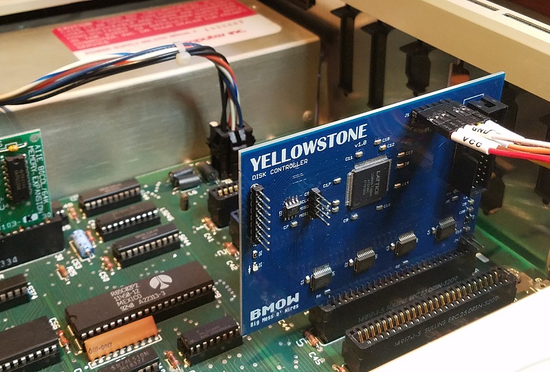
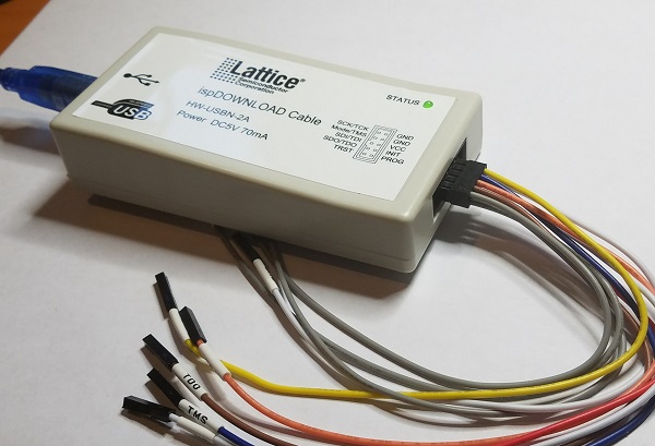
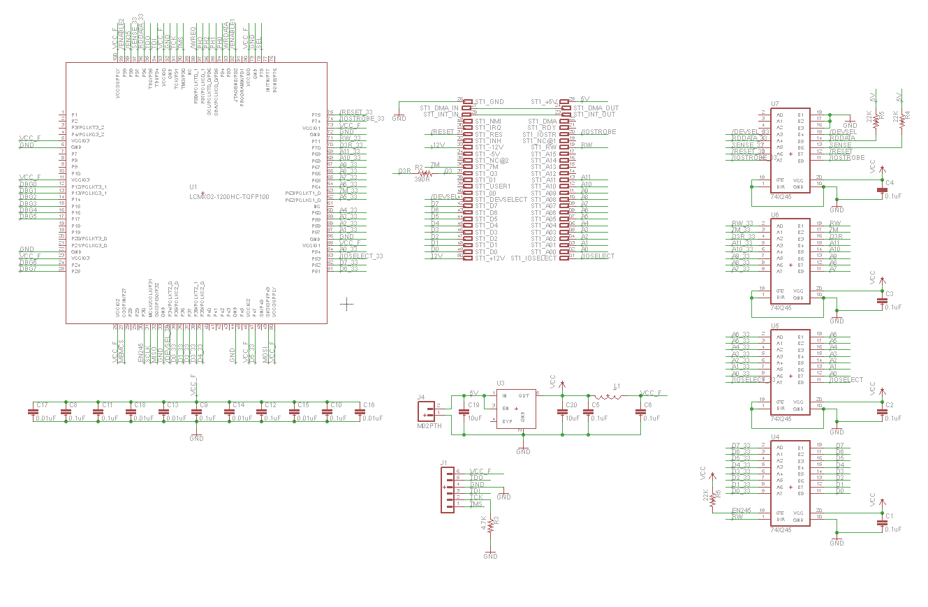
I worked like mad to finish the design in late July, just before a trip to Yellowstone National Park, which gave this project its codename. The core of the prototype board is a Lattice MachXO2 FPGA, specifically the LCMXO2-1200HC. This 100-pin bad boy has 1280 LUTs for implementing logic, and 8 KB of embedded block RAM to serve as the boot ROM or for other functions. It also has some nice features like a built-in PLL oscillator and integrated programmable pull-up and pull-down resistors. Unlike some FPGAs, the MachXO2 family also has built-in flash memory to store the FPGA configuration, so it doesn’t need to be reloaded from an external source at power-up. The FPGA can be programmed through a JTAG header on the card.
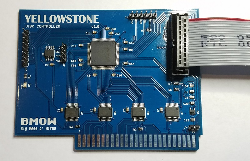
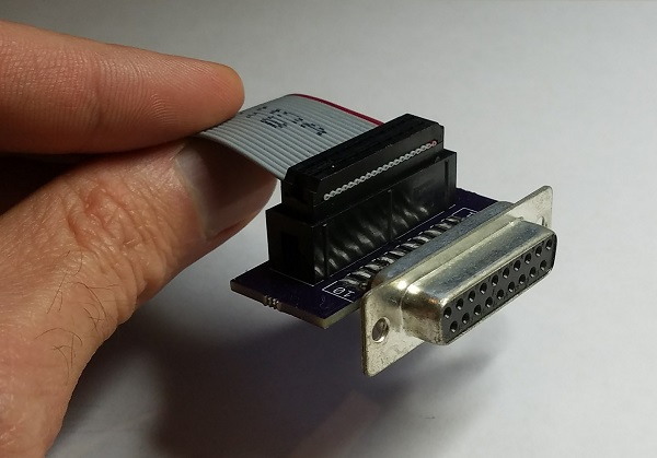
The external disk is connected to the card with a standard 20-pin ribbon cable, just like what you’d find inside an Apple IIc, or on the Floppy Emu. In fact for the Floppy Emu, you can connect a 20-pin ribbon cable directly from the Emu to the FPGA card, with no DB-19 required. For other external disk drives, I built a small adapter that converts a short length of 20-pin ribbon cable to a DB-19 female connector.
Because the FPGA’s maximum supported I/O voltage is 3.3V, but the Apple II has a 5V bus, some level conversion is needed. I used four 74LVC245 chips as bus drivers. These chips operate at 3.3V but are fully 5V tolerant, and the Apple II happily accepts their 3.3V output as a valid logic “high”. One of the chips operates bidirectionally on the data bus, and the others handle the unidirectional address bus and control signals.
There’s a tiny 3.3V voltage regular on the board, which you can see at the lower-right at U3. It’s barely any bigger than a 0805 size SMD capacitor. Even with these small components, I was still able to solder the entire prototype board myself by hand.
Just for grins I added a 2 MB serial EEPROM to the board, which you can see at U2. 2 MB is enough to store 14 disk images of 5.25 inch disks, or a single larger disk image. It’s not central to the design, but if it works then the card could function as an all-in-one virtual disk like the CFFA3000, in addition to functioning as a disk controller for external drives. More options!
Status
Here comes the embarrassing part. After July’s spurt of activity, the PCBs and parts arrived in the mail. And then I did…. nothing. Finally in October I assembled one prototype board, stuck it in my Apple IIe, and played with it for a bit. But since that day I’ve done…. nothing. I’m struggling with some internal dilemma about the balance between a hobby and a business, and doing things because I want to or because I think I should want to. I’m hoping that by publishing this summary, I may spur myself into further action.
The prototype board works as far as I’ve tested it, but that’s not very far. I verified that I can program the FPGA via JTAG, and that it responds to address and data on the Apple II bus, but that’s about it. I haven’t yet looked at what it’s doing on the external disk interface, or tried connecting a real drive. My attention has just been focused on other things, and even though I always mean to return to this project “soon”, somehow I never do.
There’s at least one serious bug with JTAG programming that needs to be addressed. When the board is outside the Apple IIe and powered from a separate 5V supply, JTAG programming works fine. But when the board is actually inserted in the IIe and powered from the slot, JTAG programming doesn’t work. It always fails with a communication error. I thought this might be some kind of noise or poor signal integrity on the JTAG traces when the board is in the IIe, but the traces are quite short and don’t cross any other signal traces that might carry interfering signals. I also thought maybe I had power problems, and the IIe’s 5V supply was drooping briefly when I tried to program the FPGA via JTAG. But as far as I can tell with a logic analyzer’s analog functions, the 5V and 3.3V supplies remain stable. It’s a mystery that will require some better tools and more careful testing.
Next Steps
What’s next for this FPGA disk controller, assuming I ever finish it? Will it become a new product in the BMOW store? That was certainly my original plan, although my lack of motivation these past months has cast some doubt on that idea. I want to keep fun hobbies fun, and not have them become an obligation and a chore, which I fear is already happening with the other retro computer gizmos I’ve developed in the past few years. We’ll see how it plays out.
Assuming this eventually becomes a new product, how will users reprogram the FPGA in order to clone a different type of disk controller? It’s not reasonable to expect that everyone will own a stand-alone JTAG programmer and know how to use it. Unfortunately I can’t see any alternative solution that wouldn’t require extra hardware and complexity, and push up the cost of the board. I might add a microcontroller and an SD card socket for loading alternate firmware, but that would be a fairly ridiculous amount of extra baggage if it were used only for JTAG. Perhaps the Apple II itself could be used as a JTAG programmer, with some extra hardware that optionally bridged the data bus to the JTAG interface? Sounds complicated, and it would leave the question of how to get the firmware onto the Apple II first. Or maybe the user could choose between a few different built-in firmwares using a switch, but would be unable to load new ones? That sounds more plausible, but would mean a bug in the firmware couldn’t be easily fixed.
Fortunately those questions can wait. The first priority is to finish debugging the prototype, connect it to some real disk drives, and verify that it works. Maybe by Christmas…
Read 38 comments and join the conversationYellowstone JTAG Debugging
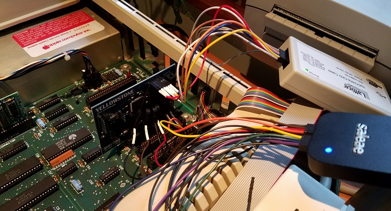
After a month of inactivity, I finally returned to my unfinished Yellowstone disk controller project to investigate the JTAG programming problems. Yellowstone is an FPGA-based disk controller card for the Apple II family, that aims to emulate a Liron disk controller or other models of vintage disk controller. It’s still a work in progress.
Last month I discovered some JTAG problems. With the Yellowstone card naked on my desk, and powered from an external 5V supply, JTAG programming works fine. I can program the FPGA to blink an on-board LED. And when I insert the already-programmed card into my Apple IIe and power it from the slot, it works – the LED blinks. But if I try to do JTAG programming while the card is inserted in the IIe, it always fails with a communication error. I’ve run through several theories why:
- It might be some kind of noise or poor signal integrity on the JTAG traces. But the traces are quite short and don’t cross any other signal traces that might carry interfering signals.
- Maybe I have power problems, and the IIe’s 5V supply is drooping briefly when I try to program the FPGA via JTAG. But I measured the 5V and 3.3V supply voltages during JTAG programming, and they look fine.
- There might be a ground loop, due to the Apple IIe and JTAG programming having different ground potentials. But I measured the difference in grounds, and it’s only 4.3 millivolts.
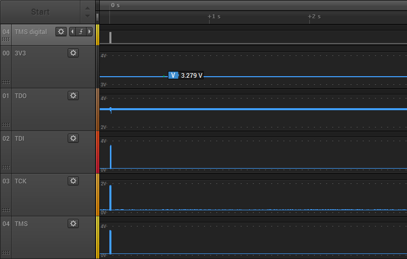
To help solve this mystery, I used the analog mode of my Saleae Pro 8 Logic analyzer. In analog mode, it functions like a simple 8-channel 12.5 Ms/sec oscilloscope. I recorded the 3.3V supply for the FPGA, as well as all the JTAG signals. First, here’s what the first three seconds of JTAG traffic look like when programmed externally:
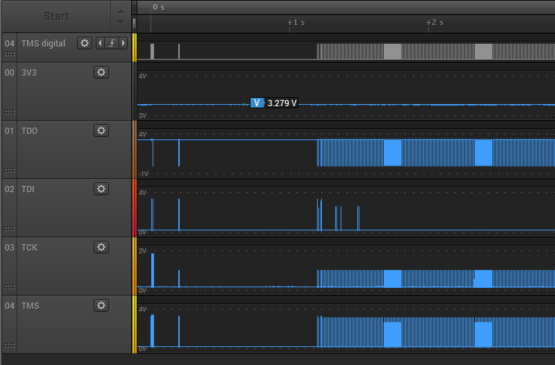
There’s about 1 second of preamble communication, and the rest is the FPGA configuration data arriving at high speed. The 3.3V supply for the FPGA remains at about 3.28V through the whole process. The JTAG signals TMS, TDI, and TDO span the voltage range from 0.17V to 3.2V, which seems fine. But the the TCK signal never goes higher than 1.86V. Uh oh, what’s happening there? Let’s zoom in a little:
Zooming in, things are even worse than they appeared initially. TCK never climbs above 1.86V, but many TCK pulses only get half that high, stopping at 0.97V. TMS and TDI show some runts too. Zooming in even further on one of the problem areas:
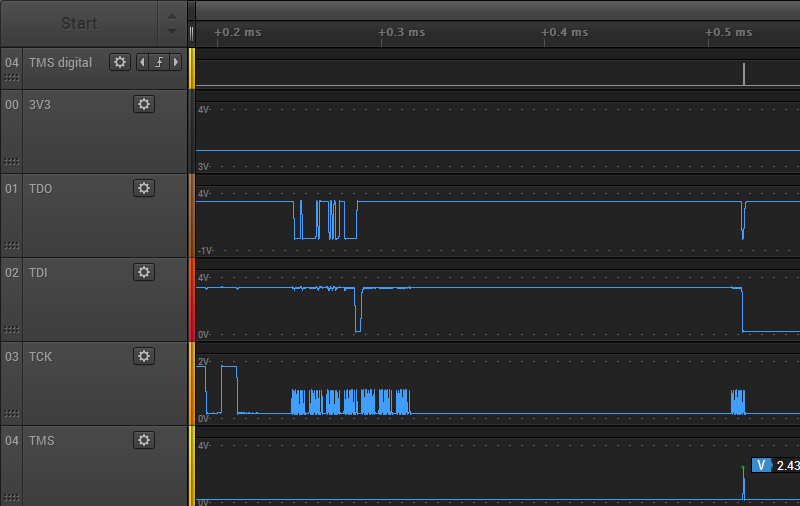
Here you can see a couple of the 1.86V TCK pulses, followed by a whole mess of the runtier 0.97V pulses. Ugh. These should all be using the full range 0 to 3.3V, or something close to it. With a clock signal this bad, it’s amazing the JTAG programming still works.
Do these graphs really reflect what’s happening? I’m a little suspicious that I’m running into limitations of the Saleae Pro 8’s analog mode. At 12.5 Ms/sec, it’s taking one analog sample every 0.08 microseconds or 80 nanoseconds. That’s pretty poor as scopes go, but the period of the JTAG clock is slow: about 1 microsecond (1 MHz operation). There should be 12.5 samples per clock period, more than enough to get a decent reading for the min and max voltage of each clock period. Therefore I think the graphs are accurate.
My conclusion is that although external JTAG program succeeds, the JTAG signals look terrible. The fact that JTAG programming fails when the card is in the Apple IIe slot likely has little to do with the IIe, and everything to do with some other basic signal quality problem.
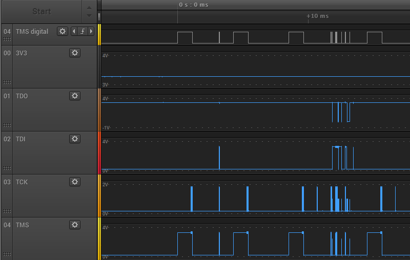
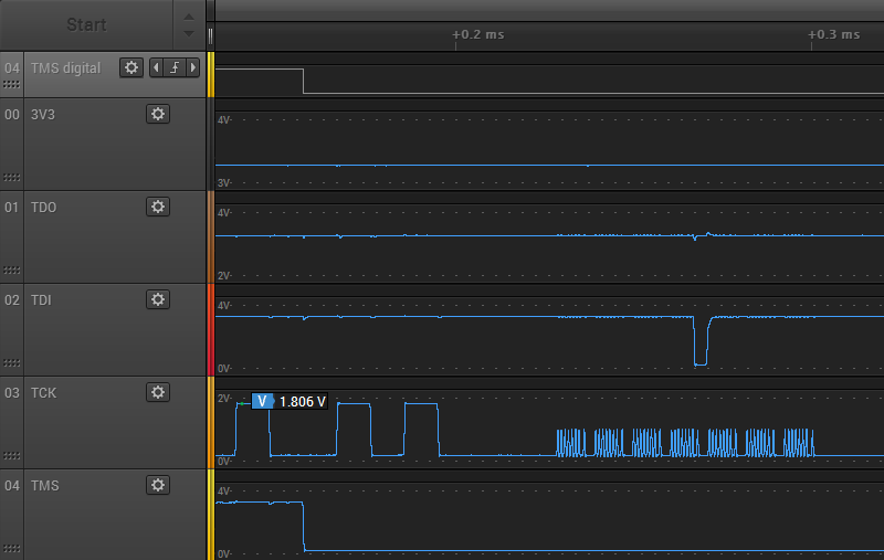
Next I put the Yellowstone card into the Apple IIe, and repeated my test. Here’s the first three seconds of JTAG traffic again:
There’s a short bit of preamble communication, then nothing. Something must go wrong at the beginning, and the rest of the communication is aborted. The voltage levels all look about the same as when programming externally. The 3.3V supply is about 3.28V, TCK never goes higher than 1.86V, but the other JTAG signals use the full voltage range. Zooming in, we observe the same extra-runty TCK pulses as with external JTAG programming:
It’s not obvious to me why external JTAG programming succeeds, but programming in the Apple IIe slot fails. Both cases look equally bad. The only real difference I noticed is the TDO signal. In the case of external programming, the TDO high voltage is very steady at about 3.268 volts, and never varies by more than 0.01V. It also drops low at many points during the JTAG communication. But in the case of in-slot programming, the TDO signal is always high and the voltage is noisier. It’s a subtle difference, but you can see the minor noise here:
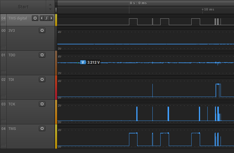
The TDO high voltage ranges from 3.187V to 3.314V, so it’s about 10x noisier than during external programming. It’s still within an acceptable range though, so maybe this isn’t important.
Finding the Culprit
Now that I know I have poor quality JTAG signals, where do I look for the cause? Poor quality JTAG programmer? Bad PCB design? Here’s a section of the PCB, showing the path of the JTAG signals from the connector to the FPGA:
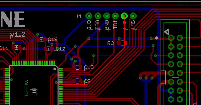
There’s not much opportunity for interference. The only PCB tracks that are crossed by the JTAG signals are voltage supplies and the disk I/O signals, which were unconnected during this test.
The prime suspect is R3, a 4.7K pulldown resistor on TCK. This was recommended by Lattice, as a precaution to prevent spurious TCK pulses causing unwanted JTAG activity when no JTAG programmer is present. Lattice technote TN1208 for the MachXO2 family says on page 12-2 “TCK: Recommended 4.7kOhm pull down.” The other JTAG signals discussed here all have internal pull-ups. 4.7K isn’t much, but maybe the JTAG programmer has an anemic drive strength and is unable to drive TCK fully to 3.3V with the pulldown present? I could try removing R3, but that wouldn’t explain why there are also some runt pulses seen on TMS and TDI. I double-checked to confirm I didn’t accidentally use the wrong value resistor for R3, but no: it’s 4.7K as intended. I also measured the resistance between TCK and GND, to see if there’s some other unintended low-resistance path to GND that’s screwing up everything, but it measured 4.7K exactly.
Read 31 comments and join the conversationNo Device Connected
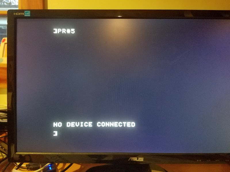
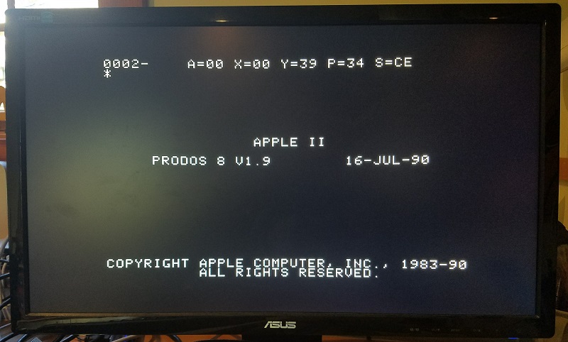
Finally, the first real progress on the Yellowstone disk controller since last summer! Sometimes an error is a good thing. It doesn’t look like much yet, but this error demonstrates that the Yellowstone card is correctly decoding address references to its slot, and is serving up data from a simulated ROM inside the FPGA. In this case the ROM data is the firmware from a stock Liron card. The Apple II’s 6502 CPU runs the firmware, which tries to use the FPGA’s soft-IWM to find a Smartport-capable disk drive. It finds none, and prints an error message. Hot stuff.
An error message is much better than having PR#5 crash the computer. That’s what happened on the many previous iterations of this test.
The next step is to stick a logic analyzer on the card’s disk interface, and see if the I/O lines are moving as expected. If that works, I’ll connect a disk drive and cross my fingers.
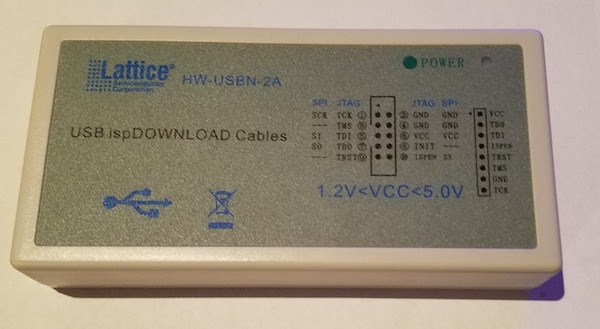
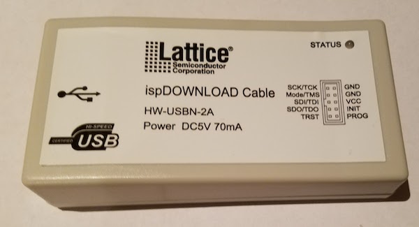
I also received another Lattice clone JTAG programmer in the mail today. This one worked on the first try, and the power/status LED works too! After a week of fiddling with my first Lattice clone, and reworking its PCB to replace the 74LS244 with a 74HC244, I finally got that one working as well. Fixing the first JTAG programmer was an interesting digression, but not really how I’d hoped to spend my time. If you’re shopping for a Lattice clone JTAG programmer, choose the one that looks like this:
not this:
Time for a celebratory beer.
Read 3 comments and join the conversationYellowstone: Cloning the Apple II Liron
FPGA-based disk control for Apple II is finally working! Six months ago, I began designing a universal disk controller card for the Apple II family. Apple made a bewildering number of different disk controller cards in the 1970s and 80s, and my hope was to replace the IWM chip (Integrated Wozniak Machine) and other assorted ICs typically found on the cards, and substitute a modern FPGA. With a little luck, that would make it possible to clone any vintage disk controller card – some of which are now rare and expensive. It would also enable a single card to function as many different disk controllers, simply by modifying the FPGA configuration. With the successful cloning of a Liron disk controller, the first major step towards those goals has been made.
Six months passed from the initial design until now, but it wasn’t exactly six months of continuous work. After a short spurt of activity last summer, the project sat collecting dust on my desk until I recently picked it up again. Sometimes it’s hard to find motivation!
Hello Liron
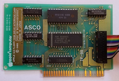
The “Liron” disk controller was introduced by Apple in 1985. More formally known as the Apple II UniDisk 3.5 Controller, it’s designed to work with a new generation of “smart” disk drives more sophisticated than the venerable Disk II 5.25 inch floppy drive. The smart disk port on the Liron is appropriately named the Smartport, and it can communicate with block-based storage devices such as the Unidisk 3.5 (an early 800K drive) and Smartport-based Apple II hard drives.
Why care about the Liron? The Apple IIc and Apple IIgs have integrated disk ports with built-in Smartport functionality, but for the earlier Apple II+ and IIe, the Liron is the only way to get a Smartport. For owners of the BMOW Floppy Emu disk emulator, the Liron card makes it possible to use the Floppy Emu as an external hard drive for the II+ and IIe. Unfortunately finding a Liron is difficult, and although they occasionally turn up on eBay, they’re quite expensive. That made cloning the Liron a logical first goal.
John Holmes was kind enough to lend me his Liron card for examination. Later Roger Shimada made the generous gift of a Liron and a Unidisk 3.5. I’m indebted to both of these kind gentlemen for their help.
The Liron contains an IWM chip, a 4K ROM, and a handful of 7400-series glue logic chips. It took a few hours to trace all the connections on the card and create a schematic. Except for the IWM, the exact functions of the other chips are all well known and relatively easy to implement in a hardware description language for the FPGA. Fortunately there’s a spec sheet for the IWM too, written by Woz himself, available if you search through dusty corners of the Internet. Based on that information, I was able to create an HDL model of the IWM for synthesis in the FPGA. It was a fairly big project, but I’d already done part of it back in 2011 for my Plus Too Mac replica.
Yellowstone Prototype
The first Yellowstone prototype was sketched out during a single hectic week. I’d never made an Apple II card before, but it’s just a standard thickness PCB with a specific shape and pattern of edge connectors. The core of the Yellowstone board is a Lattice MachXO2 FPGA, specifically the LCMXO2-1200HC. This 100-pin chip has 1280 LUTs for implementing logic, and 8 KB of embedded block RAM to serve as the boot ROM or for other functions. It also has some nice features like a built-in PLL oscillator and integrated programmable pull-up and pull-down resistors. Unlike some FPGAs, the MachXO2 family has built-in flash memory to store the FPGA configuration, so it doesn’t need to be reloaded from an external source at power-up. The FPGA can be programmed through a JTAG header on the card.
Because the FPGA’s maximum supported I/O voltage is 3.3V, but the Apple II has a 5V bus, some level conversion is needed. I used four 74LVC245 chips as bus drivers. These chips operate at 3.3V but are fully 5V tolerant, and the Apple II happily accepts their 3.3V output as a valid logic “high”. One of the chips operates bidirectionally on the data bus, and the others handle the unidirectional address bus and control signals.
The prototype card also has a 2 MB serial EEPROM. I’m not exactly sure how this will be used, but I’m hoping to find a way to load disk images from the EEPROM as well as load disks from a real drive. 2 MB is enough to store 14 disk images of 5.25 inch disks, or a single larger disk image. It’s not central to the design, but if it works it would be exciting.
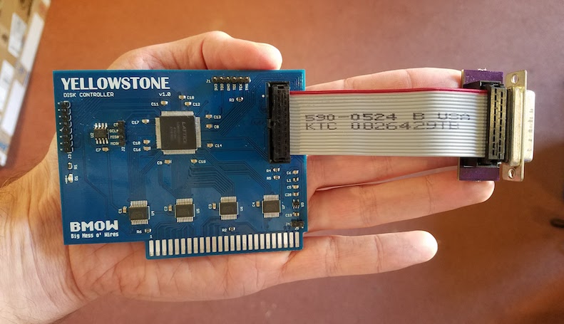
To make the physical connection to an external disk drive, I attached a short cable to another custom PCB with a DB19-F connector. The female version of the DB19 isn’t quite as difficult to find as the male, but it’s not exactly common. If Yellowstone eventually becomes a product and sells in any appreciable volume, obtaining sufficient supplies of the DB19-F will likely be a problem.
Putting it All Together
After months of procrastination, and a long digression into what proved to be a faulty JTAG programmer, I was finally ready to put Yellowstone to the test. After a few quick fixes, it worked right away! I was very surprised, considering that the complex IWM model for the FPGA was developed without any iterative testing or validation. I got lucky this time.
Here’s Yellowstone, booting an Apple IIe from a 6 MB hard disk image using a Floppy Emu Model B in Smartport mode:
And here’s Yellowstone again, booting an 800K ProDOS master disk from an Apple Unidisk 3.5 drive:
What’s Next?
I’ve made it this far – phew! Next, there are lots of little things to fix on the card. Some parts are labeled incorrectly, it’s slightly too wide, some extra resistors and buffers are probably needed for safety, etc. Addressing all those items will keep me busy for a while.
Second, I’d like to investigate cloning other types of Apple II disk controllers. The Disk II controller card should be fairly easy to clone – or the Disk 5.25 controller, which is essentially the same card with a different physical connector. I’m about 90% sure I can make that work. I would love to clone the Apple II 3.5 Disk Controller too (aka the Superdrive controller), but that would be a much larger effort and I’m not certain it’s possible. I believe the real Superdrive controller contains an independent 6502 CPU and is quite complex.
In theory the Yellowstone card could also implement other non-disk functions, although it might require a different physical connector to make use of them. A serial card maybe? Some kind of networking? A coprocessor?
The elephant in the room is the question of Yellowstone’s ultimate goal. Is it a hobby project, or a product? If a product, how much demand really exists for something like this? How would the demand change, depending on what kinds of other disk controllers I’m ultimately able to clone? And how would Yellowstone buyers update the FPGA with new firmware for new clones and bug fixes? I probably can’t assume that every customer owns a JTAG programmer and has the tools and skills to use it. But I’m reluctant to add a USB interface or microcontroller that’s used solely for JTAG/firmware updates and is dead weight otherwise. I’m still waiting for a great solution to hit me.
I’m happy the Apple II bus interface is so easy to understand and implement. Thanks to Woz for that. With just a ROM and a bit of glue logic (or their equivalents in FPGA), you can do all sorts of creative things. With today’s computers being such closed systems, I’m glad we still have antiques like the Apple II to provide an outlet for my electronics tinkering.
Read 62 comments and join the conversationYellowstone Bugs
I’ve discovered a troubling problem with the Yellowstone disk controller for Apple II, and I’m unsure how to debug it. When it’s functioning as a Liron clone, Yellowstone isn’t playing nicely with other cards like a stock Disk II controller card. While booting from a Prodos 1.9 disk image using a Disk II controller in slot 6, Prodos crashes midway through booting if the Yellowstone card is present in slot 5. This happens even if there aren’t any drives connected to the Yellowstone card. It’s not 100% reproducible, but happens maybe 90% of the time. Yet everything works fine if I repeat the test with a real Liron controller card instead of the Yellowstone card. That means it’s my problem, and not the Liron designer’s.
I believe what’s happening is this: the Apple II scans the slots beginning with slot 7, and moving towards slot 1, looking for cards with a bootable ROM. It finds the Disk II card in slot 6, and jumps to its ROM code. That code loads sector 0 from the Prodos disk, displaying the splash screen shown in the photo. Then before Prodos has finished fully loading, the Apple II resumes the scan and jumps to the Yellowstone ROM code for slot 5. This code should look for attached Smartport devices, find that there aren’t any, and return. But somewhere during the execution of that ROM code, or during execution of the Prodos code just afterwards, something goes wrong. The Apple II stops and displays a system monitor prompt. Crash.
Where do I begin, with a bug like this? I don’t really know anything about the inner workings of Prodos, or even about the ROM code on the Yellowstone card, since I simply copied it verbatim from the Liron card without really studying it. That means I can’t easily figure out what the computer is trying to do at the moment it crashes.
My first guess is that I’m experiencing data bus contention, and the Yellowstone card is interfering with the Disk II card. The Disk II controller card and the Yellowstone card might both be attempting to put data on the bus at the same time, interfering with each other, and causing wrong values to be read from ROM code. But it’s hard to imagine how Yellowstone could be driving the bus at the wrong time. The output enable logic is pretty simple, and the Apple II already provides each slot with its own fully-decoded enable signals /DEVICE and /IOSELECT. There is a region of the Apple II address space that’s shared by all cards, and that uses a shared /IOSTROBE enable signal, but the Disk II card doesn’t use that address space.
My second guess is the reverse of the first: the presence of the Disk II card is somehow interfering with the Yellowstone card, exposing a flaw in the Yellowstone design that doesn’t appear when Yellowstone is the only card present. Maybe it’s somehow causing Yellowstone to malfunction. But I can’t really imagine what could cause that.
A third possibility is a problem caused by Prodos itself, rather than by the Disk II card. Maybe the first portion of Prodos alters some memory locations or sets some interrupt timers, or changes the system state in other ways that cause the Yellowstone boot ROM to fail. But it’s unclear why such an issue wouldn’t also affect a real Liron controller card in the same way.
A final possibility: maybe there’s a hardware problem with my Apple IIe, and there’s not enough juice to power two cards simultaneously, or the logic board is flakey. In the past on this same computer, I’ve occasionally seen similar crashes to the system monitor while booting Disk II software, long before Yellowstone even existed. Coincidence, or clue?
I’m scratching my head, trying to think what I could do to help troubleshoot this further, but I don’t have any great ideas.
Read 44 comments and join the conversationApple II Card Electrical Woes
The digital abstraction of zeroes and ones is lovely, but electronics debugging often requires a deeper look into the realm of analog signals. That’s the story of my Yellowstone FPGA-based disk controller for Apple II, and it’s slowly driving me crazy. Those nice clean zeroes and ones are gone, and instead I’m struggling with voltages, logic thresholds, capacitance, and power in an attempt to explain what’s going wrong.
This story begins 12 days ago, the first time I successfully booted my Apple II using the Yellowstone card. With Yellowstone configured to clone a Liron disk controller, I was able to boot from a Unidisk 3.5 drive as well as from a Floppy Emu in Smartport emulation mode. Success! But the excitement was short-lived: it only worked when Yellowstone was the only card installed in the Apple IIe. With another card present, the computer would crash into the system monitor during power-up about 90% of the time. With more investigation, I gathered these clues:
- it didn’t matter what the other cards were
- it didn’t matter what slots the cards were in
- the crash occurred even when no disk drives were attached – so it’s unrelated to the drive or the disk contents
- the crash occurred in an Apple IIe and an Apple IIgs
- in the Apple IIgs, crashes were more likely to occur as the number of other cards increased
Based on this, I suspected some kind of electrical problem as opposed to a logic design problem. More cards means more capacitance on the data bus: maybe the Yellowstone output driver wasn’t able to switch the bus signals fast enough? More cards also means more load on the data bus: maybe the Yellowstone output driver wasn’t able to source or sink enough current to maintain a valid logic high or low voltage?
With a logic analyzer, I examined the pattern of card accesses during good and bad power-up sequences. During a normal boot, there’s a 93ms period of near-continuous Yellowstone ROM access, which is probably running the ROM code to look for an attached drive. During a boot-up where the computer crashes, this ROM access lasts a much shorter random-seeming amount of time. I measured times of 0.19ms, 1.57ms, and 28.5ms. From this I concluded that the crash is happening during execution of the Yellowstone ROM code, rather than the Yellowstone card somehow causing an error with another card or with the Apple II itself.
Some hardware background: shown above is a simplified schematic of the card (click for a hi-res version). The FPGA runs at 3.3V, powered from a Micrel MIC5504-3.3YM5-TR LDO regulator. A set of four 74LVC245 chips provide 5V to 3.3V level translation. Three of the chips are configured for unidirectional signals like the address bus and control signals, and the fourth is bidirectional for the 8-bit data bus. Each 74LVC245 has a 0.1 uF ceramic bypass capacitor about 2 mm from its VCC pin. The FPGA has twelve 0.1 uF ceramic bypass capacitors for each of its power/ground pin pairs, and its 3.3V supply is isolated from the rest of the board’s 3.3V supply with a ferrite bead, as recommended in the FPGA datasheet. There are also 10 uF ceramic capacitors on the input and output of the LDO.

So… where to begin troubleshooting? Based on suggestions from helpful commenters on a previous post, I used a scope to measure the Yellowstone card’s GND and 3.3V relative to a ground point on the Apple IIe motherboard. They both looked pretty noisy, with peak-to-peak oscillation of 680 mV for Yellowstone’s ground and 460 mV for 3.3V, at the moment Yellowstone begins to drive the data bus. But surprisingly I also observed virtually the same oscillation when Yellowstone was *not* driving the data bus and the Apple II was idle – shown in the trace above where where light blue is GND and pink is 3.3V. Then for comparison I examined a standard Disk II controller card, when Yellowstone wasn’t installed in the computer. On the Disk II card, while the Apple II was idle, I measured 600 mV of oscillation on GND and 280 mV on 5.0V. I’m not sure how to explain all this, except to note that Yellowstone’s supply oscillations don’t seem dissimilar to other cards.
At this point I tried a few quick experiments:
- Adding a 47 uF electrolytic capacitor across the Yellowstone card’s 3.3V and GND supplies didn’t make any noticeable difference.
- Connecting an extra ground wire between the Yellowstone card and a ground point on the motherboard helped a lot. The frequency of crashes after reset dropped from 90% to 20%. Hmmm.
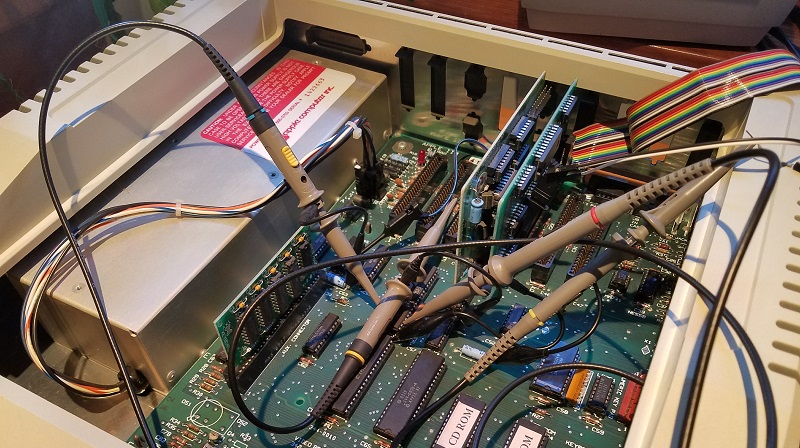
To check the data bus voltage levels and timings, I used a 4-channel scope:
- Channel 1 (yellow) – /IOSELECT – Asserted when the Apple II wants the card to drive ROM data onto the bus.
- Channel 2 (light blue) – Phi 1 – 6502 clock signal.
- Channel 3 (pink) – Phi 0 – 6502 clock signal. A read operation terminates at the rising edge of Phi 0.
- Channel 4 (dark blue) – A bit on the data bus, either D0 or D7 depending on the test.
/IOSELECT was measured at the card. Phi 0 and 1 were measured directly on the 6502. The data bus was measured at the motherboard’s 74LS245 buffer, chip UB2 on the Apple IIe motherboard.
To make a long story short, everything looked mostly fine, and I’m stumped as to why Yellowstone crashes when other cards are present. Here’s a selection of scope traces.

As a starting reference, the trace above shows a real Liron card with no other cards installed. When /IOSELECT is asserted, D0 goes high about 64 ns later. It overshoots to 4.7V before settling back to 3.8V. After the rising edge of Phi 0 and /IOSELECT is deasserted, the data bus stays high for 270 ns more. I suspect this is bus capacitance holding the old value while nothing is actively driving the bus, as opposed to the Liron card actually driving the bus beyond when /IOSELECT is deasserted.

Here’s the Liron card driving a logic low voltage on D7. The signal timing is the same as for the logic high on D0. The low voltage is about 80 mV.
I repeated both of these tests with a Liron and a Disk II card both present, and the results looked basically the same.

Here’s the Yellowstone card, with no other cards installed. The signal timing looks the same as with the real Liron card, including the 270 ns “hold period” after /IOSELECT is deasserted. D0 shows a large overshoot to 5.7V before settling back to 3.4V, which is about what I’d expect from a 3.3V card. While that’s a lower voltage than seen from the Liron card, it’s still well above the logic high threshold of 2.0V for the Apple IIe’s 74LS245 buffer.

Yellowstone driving a logic low. There’s some significant undershoot, then the voltage goes to 0V, and timing looks OK.

Now comes the interesting part: the trace above shows the Yellowstone card with a Disk II card also installed. This is the case that doesn’t work, where the computer crashes during power-up. I expected to see something wrong on the scope trace, but I didn’t. It looks very similar to previous test with Yellowstone by itself. The signal timing is the same. The high voltage overshoots to 5.4V before settling back to 3.3V.

Finally, here’s the Yellowstone card with a Disk II card also installed, driving a logic low. The bus voltage goes to 0V. It looks the same as the case when no other cards are installed.
So what now? The only thing that looks maybe concerning in these traces is the large amount of overshoot from Yellowstone when driving a logic high voltage. But the overshoot is actually less severe when a second card is installed, not more severe, which doesn’t fit the pattern of more cards leading to more crashes.
Maybe the bus voltages are only bad at certain moments, when a specific value is driven onto the bus, or some particular combination of control signals occurs? That’s possible, as my test was only able to capture the very first access to card ROM during a boot-up. If there are bad voltages appearing later, I wouldn’t have seen them.
Maybe the problem isn’t bad voltages driven on the data bus by Yellowstone, but bad voltages received by Yellowstone from the data bus and from control signals? If the Yellowstone card’s ground were pulled above the Apple IIe’s ground, it would have the effect of raising the voltage threshold for Yellowstone to receive a logic high, and cause it malfunction if signals were received incorrectly. This might explain why attaching an extra ground wire seemed to help. But from what I’ve seen of the logic signals from the Apple IIe, they’re in the 3.8V and above range, which is significantly higher than the 2.0V threshold of Yellowstone 74LVC245 buffers, even when allowing for a few hundred millivolts of ground differential.
Maybe I’m wrong about this being an electrical problem at all, and despite the circumstantial evidence, it’s actually some kind of logic bug?
Read 37 comments and join the conversation