

Halloween LED Display Demo
I’ve been working with my daughter Alice on an LED lightboard project for Halloween, and today we finished the construction. Whew! We started out two weeks ago with a giant 4 foot x 2 foot pegboard from Home Depot, and ambitious plans to make various Halloween shapes by populating specific holes. Reality quickly sunk in, though, as we realized how much work it would take to do something interesting with a 1152 hole pegboard. We eventually settled on building a much smaller 8 x 8 fully-populated LED matrix instead, controlled through software to make a variety of patterns and designs.
Even this 8 x 8 matrix was a lot of work, and for anyone contemplating a similar project, I’d recommend just buying a prebuilt LED display matrix like the Peggy 2LE instead. We probably could have found a simpler way to build the matrix, but it was a fun project nonetheless, and the result looks great. Take a look at the video, and then I’ll explain how it’s built.
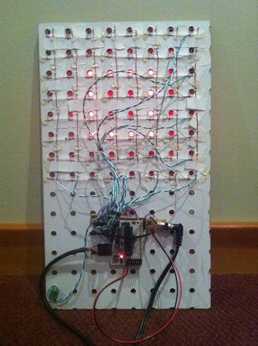
We started with a pegboard with 1-inch hole spacing, painted black on the front display side. Alice cut lengths of bare copper wire for the column busses, and lay them on the back of the board, just to the right of the holes. The bus wires were temporarily fixed in place using torn strips of adhesive tape. She then laid more bare wire on top to form the row busses, with additional layers of tape at the crossing points to ensure the row and column wires didn’t touch. The tape didn’t stick very well, so she reinforced the grid with hot glue, taking care not to cover the points where LEDs would be soldered later.
The next job was mine: building the controller circuitry. I used a MAX7219 LED driver, which is a nice (but expensive) single chip solution for controlling up to 64 LEDs. It handles all the multiplexing and storage of pixel values, so the microcontroller doesn’t have to do anything expect send SPI commands to change values when desired. The 7219 rapidly scans through the columns at about 800 Hz, activating each one in turn. This is fast enough that human vision sees them as being all active at once. The chip has sixteen driver pins: one for each row and column. It pulls one column high while the others float, and pulls rows low if the LED at that row/column intersection should be lit.
The 7219 can supply 320 mA to a column, which when divided by eight rows provides 40 mA per LED when the column is activated. Because the scanning action results in a 1:8 duty cycle for the columns, the average current per LED is only 5 mA. Typical current for an LED is about 15 mA, so 5 mA is fairly low. I was worried the display would look pretty dim as a result, but as you can see in the video, it’s actually quite bright.
I built the 7219 circuit on a piece of perfboard, hand-placing all the connections between the chip, row/column headers, control header, and power. What a mess! Whenever I build something on perfboard, no matter how simple, it always seems to turn into a giant mess with flakey connections everywhere. Unfortunately this example was no different. Soldering in the components is no problem, but I can never get the wires to stay put when soldering the connections. Any connection involving more than two wires is also a hassle. My pain with perfboards is why I favor manufacturing custom PCBs even for simple projects, but in this case there wasn’t enough time before Halloween.
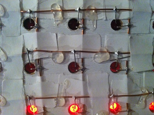
With the control circuit ready, the final construction step was to populate the board with 64 LEDs. Alice and I took turns soldering and bending LED legs to shape. It was her first big soldering project, and she had a blast. It helped that everything had wide open joints to solder, and a mistake couldn’t do anything worse than kill a 10 cent LED. Populating the whole board took about two hours, working slowly and carefully through each joint.
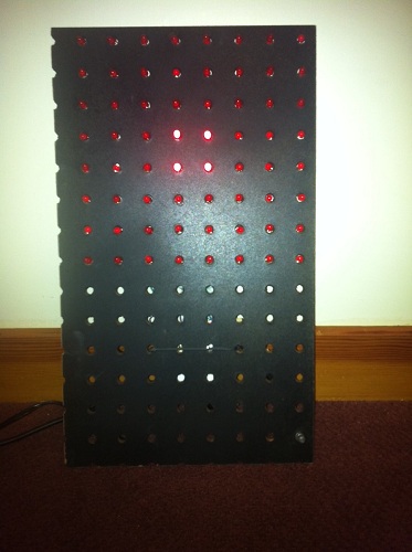
The finished board worked– sort of. It worked as long as you never lit more than 5 LEDs in a column, otherwise the display would go dark until you reset the Arduino. I wasn’t expecting this, but with my geek dad pride on the line, I had to find a solution.
My first thought was that this was some kind of clock glitch problem. I guessed that my terrible wiring combined with the sudden voltage swing from 6+ LEDs turning on was glitching the SPI clock. I spent some time fiddling with the clock wire and other control lines in an attempt to clean things up, to no avail. I also realized that a glitchly clock would likely produce display errors, but not make the screen go permanently dark, so I started looking for another explanation.
The display was finally fixed by reducing the current draw (and resulting brightness). The 7219 uses a current set resistor between two pins to control the current to the LEDs. I initially followed the sample circuit in the datasheet, using a 10K ohm resistor to provide maximum brightness. Through trial and error, I found that I had to increase the resistance to 30K before the display worked reliably. This should have resulted in a 3x reduction in current to the LEDs, but I only noticed a very minor reduction in perceived brightness.
Why was it necessary to use a larger set resistor? One possibility is that it was somehow drawing more than 320 mA with the original resistor, causing the 7219 to overheat or trip some kind of internal protection circuit. I can’t think what I might have done to make it draw too much current, though. A more likely explanation is that my shoddy power and ground wiring has a non-trivial amount of resistance, so when the current draw is high enough, +5V is pulled down and ground is pulled up far enough that either the Arduino or the 7219 no longer function. Either way, reducing the current fixes the problem, but one is a thermal problem and one is a supply voltage problem. I’ll leave further investigation for another holiday.
Now we need some cool animation displays for this board! Alice has been learning the basics of programming at Codecademy, and has already done some simple button-pushing and LED-blinking Arduino projects, so with a little help from me I think we can create a great-looking Halloween display.
Read 7 comments and join the conversation7 Comments so far
Leave a reply. For customer support issues, please use the Customer Support link instead of writing comments.
Great write-up. I’m working with the 7219 and seeing it “Brown-out” with larger # of leds on. I was thinking of going to a diff setup with higher supply but your idea of raising the R value is def worth a test!
Thanks!
BTW: I sent my daughter that Codecademy link with $20 if she completes it 😉
Good luck! After more thought, the VCC droop or ground raise theory sounds pretty likely to me. The minimum supply voltage is 4V, so it only takes 1V of combined droop and raise from a 5V supply to cause it to fail. If you’re drawing 320 mA, then it only takes 3 ohms of combined resistance in the power and ground lines to create a 1V delta. I’m not sure if a poor soldering job could result in that much resistance in a connection, but it sounds plausible.
One further thought: there’s not only a large current here, but due to the rapid multiplexing action of the lines, there is a _changing_ current. Due to the parasitic inductance of the wiring, there will be some additional voltage drop V = L * di/dt. This will be in addition to the resistance losses in the wire. In short, I think if you built this circuit carefully with short, cleanly-soldered wires, then it would perform much better. Also a simple bypass capacitor for the 7219 would probably help substantially too. I didn’t use one, did you? See http://www.vagrearg.org/?p=decoupling
[…] over at Big Mess o’ Wires has posted a terrific writeup of the Hallowe’en LED project he did with his daughter. His […]
Good work!
You always get everything working in the end.
It’s a shame you’ve only got 6 empty rows underneath the display otherwise you could put 64 push buttons in so that you can program animation frames up interactively.
Saved as a favorite, I like your website!
Feel free to surf to my weblog … led panel
Nice effect. And who’s the little lady which kindly models around the hardware ?