More Fun with Apple IIgs Disks

Last week I wrote about Apple II 800K disk emulation for Floppy Emu, which I used to boot my Apple IIgs. I posted the new Apple II firmware, so anybody with an Emu board and a IIgs could try it for themselves. Now I need help from anyone with the necessary hardware – could you take a few minutes to try it out, and let me know the results? I need as much information as I can get about compatability with different ROM versions and system configurations.
On my IIgs (ROM01 with 512K RAM and no other cards), I can connect the Floppy Emu to the DB19 port, load its Apple II firmware, and it works fine as Apple 3.5 Drive #1. I can boot the IIgs from it, using either ProDOS or GS/OS disk images. I can read and write to the emulated disk, eject it and insert a different disk image, no problems. The only limitation is that the Emu can’t be daisy-chained behind an Apple 3.5 Drive, making it 3.5 drive #2. This is because the extension cable I use, as well as the Emu itself, lacks two enable signals that are important for daisy-chaining.
Yesterday I heard from somebody for whom the Apple II firmware isn’t working correctly, on a ROM03 IIgs. He’s got the Emu board connected directly to the DB19 port on his IIgs, and is using the Floppy Emu Apple II firmware, just like my setup. But he can’t boot from the Emu: a ProDOS floppy image just hangs, and GS/OS floppy images start to boot, but eventually fail with errors like “Unable to load START.GS.OS file. Error=$002E” or “UNABLE TO LOAD PRODOS”. If he boots GS/OS from a hard drive while the Emu is attached, he sees an error about the “AppleDisk3.5 driver” midway through boot-up. They only thing that works is booting ProDOS from the hard drive, then doing CATALOG,S5,D1 to view the contents of the Floppy Emu disk.
Why does this work so poorly for him, when it works well for me? We’ve stepped through troubleshooting ideas by email, including removing the hard drive and other cards, but nothing seems to help. At this point, I think we’ve narrowed it down to either being a hardware problem with this specific Emu board or IIgs, or else a behavior difference between ROM01 and ROM03. That’s why I need as much info as I can get from other Floppy Emu users who’ve tried this firmware on their IIgs.
Apple II Disk Daisy Chaining
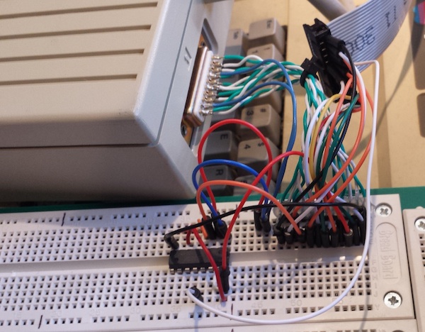
Fortunately there’s some good news among all of this. Remember those two enable signals I mentioned, important for daisy-chaining, but not present on the Emu or Emu cable? Yesterday I put together a hand-made DB19 to IDC20 adapter on a breadboard, along with an external logic chip, and got the Floppy Emu working successfully while daisy-chained as 3.5 drive #2. The adapter is the rather unattractive jumble of wires you see in the photo at the top. While it’s of no immediate value to anybody, the fact that this adapter works seems to confirm that my understanding of all these crazy Apple disk enable signals is correct.
Here follows a long boring discussion of enable signals. Refill your coffee now.

On a Macintosh, pin 17 of the DB19 floppy connector is the drive enable signal. When it’s low the drive is enabled, and when it’s high the drive is not enabled. Only one floppy drive can be connected, so there’s only one enable signal.
On an Apple II, things are more complicated. The Apple 5.25 controller card was the first to use a DB19 connector, and it supported two daisy-chained 5.25 inch drives. Pin 17 is /DRIVE1 enable, and pin 9 (unconnected on the Macintosh) is /DRIVE2 enable. Within each drive, internal circuitry routes the signal from input pin 9 to output pin 17 on the daisy-chain connector. Drive #2 doesn’t actually know that it’s drive #2 – it enables itself by observing /DRIVE1 on pin 17, just like the first drive – only the first drive has sneakily rerouted /DRIVE2 to /DRIVE1. This allows for two drives to be daisy chained.
On an Apple IIgs, it’s even more complicated. Its DB19 connector supports daisy-chaining two 3.5 inch drives, and two 5.25 inch drives – as well as even more SmartPort drives, which I won’t discuss now. Pin 4 (GND on the Macintosh) is /EN3.5, a new signal that enables the 3.5 inch drives when it’s low, or the 5.25 inch drives when it’s high. The 3.5 inch drives must appear before any 5.25 inch drives in the daisy chain. When /EN3.5 is low, the 3.5 inch drives use pins 17 and 9 to enable themselves, and when /EN3.5 is high, the 3.5 inch drives pass through the signals on pins 17 and 9 unmodified to the 5.25 drives behind them.
This is getting complicated, but there’s one final kick in the nuts: when the first 3.5 drive is enabled, by the IIgs setting /EN3.5 and /DRIVE1 both low, you would think the drive would disable the next 3.5 drive behind it by setting both /DRIVE1 and /DRIVE2 high at the daisy-chain connector. But no, the first 3.5 drive disables the second 3.5 drive by setting both /DRIVE1 and /DRIVE2 low! This looks like both are enabled at the same time, which would be a definite no-no, but the Apple 3.5 Drive contains circuitry that recognizes this “double enable” as being equivalent to a disable. Why it’s done this way, I don’t know, but I’m sure it has some purpose.
The end result is that for proper behavior in either first or second position, a Floppy Emu trying to emulate a 3.5 drive should respond only if /EN3.5 and /DRIVE1 are low and /DRIVE2 is high. All three signals must be checked.
Floppy Emu doesn’t have connections for /EN3.5 or /DRIVE2, so it responds whenever /DRIVE1 is low. When connected as a second 3.5 drive, that means it’s unable to recognize the “double enable”, and it responds at the same time as the first 3.5 drive, so neither of them work properly. But when connected as the first 3.5 drive, there’s no double enable to worry about, and /DRIVE2 can be safely ignored. Ignoring /EN3.5 does mean the Emu will also respond to attempts to access 5.25 drive #1, but since there is no such drive anyway, that’s not really a problem.
Building an Adapter
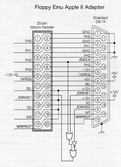
So how can we solve this mess, without requiring a new version of the Floppy Emu? The solution I’ve used is to combine the /EN3.5, /DRIVE1, and /DRIVE2 signals externally, and feed the result to the Emu’s single /ENABLE input. I used a 74LS138 decoder chip to do this, configured to drive a single output low only when the inputs are 0, 0, and 1 respectively. You could accomplish the same thing with a few OR and NOT gates as well. Here’s a schematic:

At some point in the future, I’ll probably manufacture and sell some adapter boards like these. The best way to put the idea into production isn’t obvious, though. This adapter design has 3.5 inch specific functionality baked directly into its circuitry, and it would be wrong if you were using the Floppy Emu to emulate a 5.25 inch or SmartPort disk, or a Mac disk. It would be annoying if people had to attach and remove an adapter every time they wanted to change what type of disk they were emulating. Maybe I could put a switch on the adapter, to select between 3.5 inch and other emulation modes, but that would be annoying too and would add further to the hardware cost. Nobody wants to flip an external switch – they want to select an emulation mode, and just have it work.
Another uncertainty is what form this adapter would take. Should it be an inline adapter, with an IDC20 connector for input and another for output? That would work, but it would mean Apple II users would need a DB19 to IDC20 extension cable, and an adapter – two different things to connect between the computer and the Emu board. A better solution is probably to make a new version of my DB19 to IDC20 extension cable, that has the adapter circuit and switch built into it. But that would drive up the cost by a few dollars – so would I continue to sell the old cable as well, or encourage everyone to buy this new, more capable but more expensive cable? If I sold both cables, would I get tons of email from people confused about which one to buy, or upset because they didn’t understand they needed a specific cable to enable specific types of emulation?
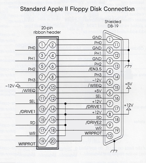
There’s another matter too – for most purposes the DB19 and IDC20 connectors are interchangeable, and there’s a standard pin mapping between the two, shown above. But the /DRIVE2 signal on DB19 pin 9 was only ever used in DB19 cables, and there is no standard mapping for it on the IDC20 connector. So how can I even physcially route that signal on a 20-pin ribbon cable? I could substitute it for one of the existing signals I’m not currently using, like one of the +12V supply lines. That would be fine for Floppy Emu and my adapter boards, but someday someone would surely use one of my cables to do something strange, like connect a Disk II to an Apple IIgs. Then they’d get +12V from the Disk II feeding backwards into the computer’s /DRIVE2 output, causing it to burst into flames and burn down their house.
Sometimes I think about things too much. 🙂
Read 3 comments and join the conversation3 Comments so far
Leave a reply. For customer support issues, please use the Customer Support link instead of writing comments.


Probably nothing you don’t know, but I also found this last night, and it seems to relate some of the pieces between the Apple II, Apple3.5 and Smartport stuff…
http://mirrors.apple2.org.za/apple.cabi.net/FAQs.and.INFO/DiskDrives/drive.order.txt
Steve, also, even if I boot the ROM1 IIgs over AppleTalk (I didn’t try the HD in here) to GSOS 6.0.1 I get the same error about the “AppleDisk3.5 driver” midway through boot-up. So this is not a pure ROM1/ROM3 issue.
Hi,
I do not get the note about chaining 2 3.5″ and 5.25″ together.
The first drive gets enable with /drive1 and /en3.5 and then forwards /drive1 low and /drive2 low. You reason there is a logic that the second drive identifies this special case, referring esp. to 3.5″ drive’s logic boards.
What if I have 1 3.5″ drive and two 5.25″ drives. The 3.5″ drives ‘disables’ the followers by /drive1 and /drive2 low … hitting the 5.25 (first) directly? The 5.25″ does not see the /en3.5 signal actively, I presume? Hmmm, what does the 5.25″ drive know about this? Do they also have an inhibiting logic for this case? So if both are low, the boards just cut it?