

Floppy Emu Technology Design

Floppy Emu was developed here at Big Mess o’ Wires, over a period of several years. You can view the tech planning, problems, and progress reports from the development blog if you’re interested in its history and operation. There’s a wealth of information on all the nitty gritty details and issues solved along the way, so check it out!
Floppy Disk Theory
Every floppy disk drive communicates with its attached computer by reading and writing a stream of serial bits. On the floppy disk media, these bits are stored as magnetic flux transitions in concentric circular rings called tracks. As long as the read/write head is positioned over a particular track, and the disk is spinning, the same circular stream of bits will be sent to the computer over and over. It’s the computer’s responsibility to make sense of this bit stream: identifying the boundaries between bytes, decoding the “disk bytes” into standard data bytes, locating specific sectors in the bit stream, and so on.
Outside of the bit stream itself, floppy drives also provide several control signals. The computer can turn the drive motor on/off, and move the read/write head to the next track inward or outward – a process called stepping. Some drives can report whether a disk is currently inserted, and can be instructed to eject the current disk.
Individual floppy designs vary widely. The number of tracks and their relative spacing varies from one design to another. Some drives have tracks on both sides of the disk media, and some only on one side. The density of the magnetic flux transitions can vary, as well as the bit rate of the serial bit stream. The speed at which the disk rotates differs among designs too. A few drives even use different rotational speeds for different regions of the disk. Some disks have a physical marker to indicate the location of the first sector on each track, while others are soft-sectored. Data isn’t typically recorded directly as magnetic flux transitions, but instead is encoded as specialized disk bytes, and this encoding format also varies between drive designs.
Making an Emulator
Building a floppy disk emulator requires creating hardware that acts identically to a floppy drive, as far as the computer is concerned, but that doesn’t actually use floppy disks. Typically a floppy disk image file is loaded from a memory card, USB, or another source, and stored in the emulator’s on-board RAM. The emulator then looks at the stepping commands and other information coming from the computer, and uses them to determine which portion of the disk image the computer is trying to access. It then synthesizes a virtual track on the fly, creating a serial bit stream with the desired data, with the proper bit rate and encoding.
Most floppy emulators use a PIC, AVR, ARM, or other similar microcontroller as the brains of the device. The mcu does all of the hard work, fetching disk images from memory cards or USB, and communicating with the host computer. For most floppy emulators, a single microcontroller is the only complex chip required.
The Sony floppy drives that are used in Lisa and Macintosh computers operate differently from the floppy drives in virtually every other computer, and these differences make it challenging to create a Mac/Lisa floppy emulator. Unlike other drives which spin at fixed speeds, the Sony drives spin at a variable rotation speed, depending on which track is being accessed. The drive reports its current rotation speed to the computer, and the computer will check that the speed is within an acceptable range before performing any disk I/O. This speed reporting must be performed in parallel with the actual data bit stream. Depending on the microcontroller used, generating two truly parallel bit streams may be difficult or impossible, since the mcu is typically a single-threaded device.
The second big difference between Mac floppy drives and others is the way control signals are handled. A standard PC-style floppy drive has a 34 pin connector, with each control signal broken out onto a separate pin. This makes it relatively easy for a microcontroller to poll the control inputs whenever it wants, and set the status outputs on the appropriate pins. In contrast, a Mac floppy drive has a 20 pin connector, with the control signals multiplexed like a 16 x 1-bit register file. The computer selects one of 16 different control signals by putting its address on 4 pins, then reads or writes the control value with a 5th pin. This style of control is almost impossible for a microcontroller to emulate by itself, because it would require lightning fast interrupt response times to any changes on the address pins.
To address the unique challenges of emulating a Macintosh floppy drive, Floppy Emu combines a CPLD with a microcontroller. The CPLD is a programmable logic chip, like a smaller version of an FPGA, and it can handle true parallelism and nanosecond-level response times to input changes.
HD20 Hard Disk Emulation
The HD20 was an early model of Apple hard disk that connected to the Mac via the floppy port. Functionally it had virtually nothing in common with floppy drives, except for sharing the same connector. While a floppy drive is effectively a dumb device in which the computer directly controls a motor and a read/write head, the HD20 was a smart device with its own internal processor. The computer sent commands to the HD20, using an Apple-specific protocol called DCD – directly connected disk. The HD20 then replied with a DCD response. A typical exchange might have involved the computer requesting 4 sectors beginning at sector number 288, and the HD20 responding with the contents of those sectors.
Although the HD20 had a capacity of only 20 megabytes, the DCD protocol can support much larger disks. With an update to the CPLD and microcontroller firmware, the Floppy Emu is able to speak the DCD protocol, and emulate hard disks up to 2 GB in size for those Macintosh models that support the HD20.
Floppy Emu
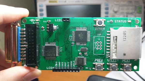
The Floppy Emu hardware consists of a Xilinx XC9572XL CPLD working cooperatively with an ATMEGA1284 AVR microcontroller. The CPLD implements all the timing-sensitive functions and communication with the Macintosh, while the microcontroller provides the brains of the device. The microcontroller uses SdFatLib to read sectors from a disk image file on the SD card, and synthesizes sector headers, footers, and checksums on the fly. It also performs the necessary conversions between logical data and the GCR encoded data format used on Macintosh floppy disks. The microcontroller then passes the bytes one at a time to the CPLD, at a speed that mimics a normal floppy drive. The CPLD performs the parallel-to-serial conversion and implements the serial signalling convention expected by the Mac. To the Mac, the emulated floppy disk appears identical to a real disk in speed and capacity.
Using a built-in bootloader, the AVR microcontroller’s software can be updated from the SD card. The CPLD’s configuration firmware can be updated as well, using the mcu to program the CPLD via JTAG. This means an external Xilinx JTAG programmer isn’t needed.
2 comments2 Comments so far
Leave a reply. For customer support issues, please use the Customer Support link instead of writing comments.
Hey Steve, how would I be able to build my own for an extra challenge?
That was an old reference and that option is no longer available, sorry.