

Notes on Video
The high-level design of the BMOW video system is mostly complete now, but is scattered across eight pages of scrawled notes and the inside of my head. It’s proving to be a complex beast, and there are still many smaller details I need to resolve, but I think I’m finished with the worst of it. Hans Summers’ custom-built Z80 video circuit design validated my original approach, and provided a few key ideas for getting more flexibility from the same amount of hardware.
My design has a screen resolution of 320×240, and devotes 64 bytes of video memory to each scan line. Of these, 40 are used to create the visible portion of the line, and 24 are unused. This wastes a considerable amount of memory, but it simplifies the hardware, and memory is cheap. The simplest case is text mode, in which each of the 40 bytes translates to a character to display, and each character is composed of an 8-pixel wide black-and-white bitmap, so 40*8 = 320 and the screen gets filled with text. Here the resolution is 1-bit-per-pixel, as each of those 320 pixels is one of two colors.
Things get more interesting in the graphics modes. I’m especially happy that I found a way to support the 1bpp text mode as well as 2bpp, 4bpp, and 8bpp graphics modes all through software changes to the color palette, without any hardware differences for the different bit depths. At the same time, I was also able to eliminate the shift register that most video generators need for shifting out the bits in a byte to create pixel data. Again, the answer is the color palette. Here’s a diagram:
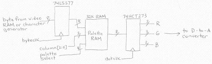
At the left, bytes are clocked in from video RAM or the character generator. For text mode they’re clocked at one byte every 8 pixels, and for graphics modes bytes are clocked at one every 4 pixels. The byte is then passed to the palette RAM as part of its address, along with the lowest three bits of the column count. Four bits of palette select are also provided, so the software can quickly change between several different ones. Think of the RAM as a lookup table, that determines the color to display as a function of the data byte and the three bits of column count. Using those inputs, it’s possible to create 8bpp, 4bpp, 2bpp, or 1bpp just by storing different color data in the palette. For each increase in bit depth, the pixels get twice as wide, so you can get 320 pixels @ 2bpp, 160 @ 4bpp, or 80 @ 8bpp.
Here’s how it works. For 1bpp operation during text mode, you set the palette so that the three column bits select one of eight “sub-palettes”, corresponding to the eight columns. Each of those sub-palettes then contains the value for white whenever the bit in the corresponding column is set, and black otherwise. No shift register is needed to create the eight output pixels. The palette looks like this (X means “don’t care”):
| column[2:0] | data byte | color |
|---|---|---|
| 000 | XXXXXXX0 | black |
| 000 | XXXXXXX1 | white |
| 001 | XXXXXX0X | black |
| 001 | XXXXXX1X | white |
| 010 | XXXXX0XX | black |
| 010 | XXXXX1XX | white |
| 011 | XXXX0XXX | black |
| 011 | XXXX1XXX | white |
| 100 | XXX0XXXX | black |
| 100 | XXX1XXXX | white |
| 101 | XX0XXXXX | black |
| 101 | XX1XXXXX | white |
| 110 | X0XXXXXX | black |
| 110 | X1XXXXXX | white |
| 111 | 0XXXXXXX | black |
| 111 | 1XXXXXXX | white |
For 2bpp, you create four sub-palettes, selected by the two higher-order column bits. Each of these contains one of four color entries, depending on the pair of data bits corresponding to the column count. Similarly for 4bpp to select one of 16 colors. For 8bpp, the column bits don’t matter, and the entire 8-bit byte is used to select one of 256 colors.
If this seems confusing, another way of viewing it is that the horizontal resolution is always 320, and the hardware outputs four pixels at a time. Those pixels can all be different colors, or pairs of identically-colored pixels, or a single 4-pixel block of color.
Since the palette RAM is a normal memory with 8 bits per address, the palette entries are 8 bits wide. They define 3 bits of green, 3 bits of red, and 2 bits of blue color data, which is then latched in an output register, and finally converted to an analog voltage for the VGA monitor. 8-bit palette entries certainly aren’t ideal. There’s more precision for red and green than blue, and the overall precision is poor. In fact for the 8bpp indexed color mode, the indexes are as large as the palette entries themselves, and you could just as easily use them directly as color data, skipping the palette entirely!
I’m hoping that 8-bit palette entries will be good enough for my purposes, but if not, I could add a second palette RAM in parallel with the first, and pass it the same address data. That would effectively create a 16-bit wide memory: enough for 555 or 565 encoding of the RGB color data, which should look pretty good. Unfortunately it would add an additional RAM chip, a second output register, and require doubling the size of the DAC, so it might well be more trouble than it’s worth.
Be the first to comment!No comments yet. Be the first.
Leave a reply. For customer support issues, please use the Customer Support link instead of writing comments.