

Apple II Machine Language Monitor
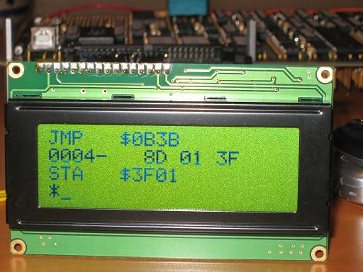
While waiting for the parts I need for the video system, I ported the machine language monitor from the Apple II ROMs to BMOW. Somehow I’d never gotten around to writing an interactive program to examine and modify memory, which I’ll certainly need once I start trying to poke bytes into video memory and see something on the screen. Rather than write my own monitor program, I decided it would be interesting to port the Apple II’s. BMOW’s instruction set is mostly a superset of the 6502 CPU in the Apple II, and the monitor program’s source code is listed in the famous Apple II “Red Book”. It was written by Steve Wozniak and Allen Baum in 1977. I figured it shouldn’t be too hard to convert it for BMOW’s purposes. After a longer than usual amount of fiddling I have it mostly working now, but it proved to be a major pain in the ass! Here’s a photo of the monitor program in action, showing a disassembly of itself.
The monitor is pretty darn impressive for a 2K program. Its features:
- Examine a single memory location or a range of addresses
- Disassemble a program at a given address
- Store one or more user-supplied bytes beginning at a given address
- Block move memory
- Compare two blocks of memory
- Run a program at a given address
- Single step a program at a given address
- Perform hexadecimal math using a built-in calculator
The original Apple II version also included an assembler, as well as functions to read and write data from a cassette tape. Ah, those were the days!
To port the monitor program to BMOW, I expected I’d need to solve a couple of problems:
- Replace the original keyboard input and screen output code with BMOW equivalents
- Adapt the output for a 20×4 LCD, instead of the original 40×24 television
That wasn’t too difficult. The bigger problem I hadn’t expected was that BMOW was much less 6502-compatible than I’d thought. In particular, which condition codes are set by which instructions differed quite a lot between the 6502 and BMOW. It turned out that the Apple II monitor relied substantially on the fact that certain instructions like INC would set the zero and negative flags, but leave the carry flag untouched. BMOW wasn’t designed to work that way, and unfortunately it took me many hours of digging through the source code to understand how it worked before I picked up on this detail, and even longer to find and fix all the instances where it caused bugs. My BMOW simulator proved to be extremely valuable, and I even spent some time to add rudimentary source-level debugging to the simulator. The good news is that I found and fixed a lot of BMOW microcode bugs, and I was eventually able to find a way to change BMOW’s condition code usage to match the 6502’s by reprogramming a GAL, with no wiring changes at all. And now I have a working monitor program!
After spending all that time in the monitor source code, I’ve come to know it pretty well, and I have to say that Woz and Baum must be crazy! OK not crazy, but they certainly approached programming much differently than people would today. The program makes widespread use of some pretty bizarre techniques which I’m sure were intended to economize every last byte. Functions are constantly calling into the bodies of other functions to borrow a little snippet here or there, so it becomes difficult to identify which bits of source code are related to any particular program feature. Conditional branches are used in many cases where it’s obvious that the condition will always evaluate true, which I think is because the conditional branch instruction takes less program space than an unconditional jump.
Beyond that, it also looks as if they intentionally designed the program so that certain parts of it would end up at very specific memory addresses. The program is precisely 2048 bytes. There are NOPs and padding bytes in a couple of places, and in a few places I saw a bigger instruction used where a smaller one could have been. For example, some code does a branch to another instruction, which is a RTS (return from subroutine). Why not just put the RTS in directly instead of having the branch? It seems that Woz and Baum may have started with goal addresses in mind for portions of the program, so that certain address arithmetic would work out nicely and save a few instructions, and then they went out of their way to make sure those goal addresses were achieved.
Maybe Woz or Baum or someone else who knows will follow up and explain what they were thinking; I’d be curious. Years ago I once received a shareware registration from Woz for a Macintosh game I wrote, it was a $10 check (signed simply “Woz”). In retrospect it might have been fun to hang on to, but I cashed it. After that we exchanged a couple of emails, though, and I even sent him a game T-shirt. I wonder if it’s still wedged at the bottom of his dresser drawer.
Read 11 comments and join the conversation11 Comments so far
Leave a reply. For customer support issues, please use the Customer Support link instead of writing comments.
Wow!
That is one heck of a good example of talent. I must say you’ve gone and done the impossible.
At one time I specialized in writing 6502 assembler, and even worked out how to do things most people did using BASIC, except for graphics, and of course, math.
Next question, can you recall when you bought the Red Book on the monitor that the Apple wore? I remember seeing a copy in my favorite computer store, and naturally ignoring it.
Incidentally who makes the LCD display that you are using?
Thanks Greg! I’m still learning the ins and outs of 6502 assembly. I know what all the instructions do, but I haven’t really learned all the “tricks” of which ones to use to achieve a desired purpose. Digging through Woz’s code was a good tutorial, though.
I don’t have a physical copy of the Apple II Red Book, but a nicely recreated PDF version of it is here: http://apple2history.org/dl/download.pl?file=redbook.pdf
The LCD is a generic 20×4 text display with an 8-bit parallel interface. It uses the standard Hitachi LCD interface that seems to be shared by every LCD on the planet. I think I bought it from Futurlec for $5 or so.
Good progress! The video ideas will be helping me in the future. I’ll do that project later…
Will the video run separately from the processor? I mean will the ram be continuously clocked out, that way the processor only has to update the changes. That’s how I would do it, but I suppose there are drawbacks. Also, you mention “GAL”s I’ma look them up. Any recommended reading on that?
Exactly, the video circuit will be constantly reading data from memory to create the VGA signal, and will only be interrupted when the CPU wants to read or write that same memory. Like you said, the CPU doesn’t need to do anything at all to refresh the screen at 60 Hz, it only needs to worry about making changes to the screen data.
GALs are rewritable PALs, which are a very simple form of programmable logic. They’re a precursor to modern devices like FPGAs. The type I’m using is a standard 24-pin DIP chip with 12 inputs and 10 outputs, where each output can be programmed to perform an AND/OR equation of the inputs. They’re helpful for reducing the number of chips in your project, but you could get the same result with a few regular AND/OR chips like the 74LS32. I wrote an article about using GALs for electronics projects a while back for uCHobby: http://www.uchobby.com/index.php/2008/03/30/gals-for-electronics-hobby/
That was a great help! I looked at the isp options, as that would probably be easier – I already have an atmel isp programmer. I’d wanted to get into some form of programmable logic. I aim to somewhat re-create what you are doing with video.
My goal is to create counters, and certain logic chips like buffers, multiplexers and the sort. I suppose GALs and CPLDs are my solution. I’ll see about buying some of these because I have an ISA backplane I need to fill up with electronics!
Time to start designing! Also, as an afterthought, my work is getting rid of a lot of old isa cards, some of which are video, before we scrap/recycle them, should I be looking for anything of interest? There’s one from the mid 90’s that caught my eye…
It might be worth digging through those old ISA video cards for a video palette chip, if you’re planning on doing a video project at some point. Look for a 28-pin chip labeled UM70C171 or IMSG171. That’s the VGA palette chip I wrote about earlier.
As for me, I’d originally planned to stick with my custom design for the video output stage, and not use the UM70C171 I found at Weird Stuff. After cranking through the design details some more, though, I think I may change my mind. At this point my custom design looks like it’ll be 20 chips, which will just barely fit in my remaining board space, with no space left for future audio chips. Using the UM70C171 would cut that to 17, which would help.
But more importantly, I think using the UM70C171 would increase the chances of the whole thing working successfully at all. The timing requirements of the output stage are pretty tight; since I’m now targeting 640 pixels of horizontal resolution, that’s just 40ns per pixel. I need to pay very close attention to the setup, propagation, and hold time requirements from the datasheets to create a successful output stage circuit using plain registers and RAM, and I’ll probably need to use faster 74AC or 74ACT components.
I’m also not confident my custom built D-to-A converter using resistor ladders will produce good-looking results. I’m sure it’ll work to a degree, but I think there will be substantial amounts of error in the D-to-A conversion due to not having exactly the right resistor values. Also the register I would use to drive the D-to-A converter is just a regular 74HCT273, and its logic “1” outputs won’t necessarily be exactly 5v, but will probably vary a little depending on the state of all the other inputs and outputs. In practice the effect may be negligible and the result may look fine, but I can’t be sure until I build it.
On the other hand, using my custom output stage wins me more nerd credit points. Using some fancy-shmancy VGA chip feels like cheating, in a way. The custom design also gives me more flexibility (256 simultaneous colors, different palettes per line) that I’d lose if I switch to the UM70C171. So I guess it’s a choice between a more flexible and “cool” custom design, versus a simpler, more reliable one.
Well, I just did a few maths (poor they were ;)), and I wired up a divider. It just works out to give me 120hz and 31.? khz with 1MHz input. Its divide by 5 and divide by …14. 15 works as well.
I’ma post a picture of what it looks like – bad. as long as I feed somewhat regular signals to the monitor, it will turn on, and if I press menu, it will attempt to display a menu at that resolution… It’s having a bit of trouble with these 50% duty cycle sync signals! I suppose I’ll have to sacrifice a $4 ATMega168 to do the job >.>
Oh, about your DAC: I built an 8 bit R/2R DAC with some 1% resistors (I think) I had. It was fine for audio, haven’t tried with video yet. It worked alright without a buffer as well.
About your audio: You can do it all on one Atmel uC, otherwise, I’d consider using digital to analog conversion and voltage control, or a synthesis chip like the speakjet or SID.
BMOW could always use another mainboard, but that kind of traps you in an endless loop of ever-expanding complexity. Imagine ethernet and wireless and a floppy drive, oh boy.
Thanks for the info HDL-SDK. Post a link to a photo of your creation! I’m sure you’ve seen the summary of VGA sync timing specs at http://www.epanorama.net/documents/pc/vga_timing.html . It should be about 60Hz vertical and about 31.5kHz horizontal for 640×480. It’s definitely not a 50% duty cycle though, so I’m surprised your monitor was able to make sense of it at all.
I guess an unstated goal of BMOW is to build everything from the simplest parts possible. There are plenty of cool microcontrollers and programmable elements that I might have used, and for that matter I could probably have built the entire thing using a single FPGA. That seems much less satisfying to me, though. Ideally I would have built everything using just 7400-series stuff and RAMs and ROMs. I made a concession for the GALs, since they’re still fairly “old school” being mid-80’s technology. I used a modern FTDI chip for USB connectivity, since there was no other choice. That’s why I’m reluctant to use the UM70C171 instead of a totally custom solution, and why I probably wouldn’t use a microcontroller for audio either.
You’re right about the endless loop of expanding complexity. I’m definitely planning to keep to one board, and I’m looking towards the end of the hardware construction phase for BMOW. I’m hoping I can fit on video, rudimentary audio (maybe just bit banging the speaker), and some kind of non-volatile storage (probably battery-backed RAM), then I’ll call it finished.
It’s amazing
Hi there!
My first post at this great blog!
I wanna show u my dayly updated blog: Black Amateur Fuck Video
Have a nice day!
BB!
P.S. if you don’t want to see this message please write me to no.ads08@gmail.com with subject “NO ADS” and URL of your forum
Thank you for cooperation!
[…] Thu 11-12-2008 $12 MIT Computer Based On NES, Not Apple II Saved by anniekbm on Mon 08-12-2008 Apple II Machine Language Monitor Saved by LittleAkamaru on Sat 06-12-2008 VisiCalc, la “killer application” per Apple II Saved […]