

Progress on Audio
I’ve made some good progress on the audio hardware, working with the SN76489 and an Arduino microcontroller to help test things out. I put those components plus a clock generator on a breadboard, and wrote some simple Arduino programs to exercise the SN76489’s inputs. It didn’t take too long to get some simple tones, but I expect it will take much longer to learn to use the sound generator creatively to get the best possible results. Here’s a video of my contraption playing a continuous chord with one of the three voices ascending and descending:
I’m still not really sure what the “correct” way to connect this part to an external speaker is, but here’s the schematic showing what I did: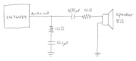
The first 10 Ohm resistor and 0.1 uF capacitor are there because they were in the datasheet for the related SN76494, to “prevent oscillation”. Whether they’re present or not doesn’t actually seem to make any difference, on the scope or to my ear. The 470 uF capacitor is there to remove the DC bias from the SN76489’s output, which swings back and forth around an average of roughly 3 volts. Without it, the circuit still works, but the sound isn’t as loud. The value of 470 uF was pure chance: I tried some smaller values around 1 uF, but they messed up the audio waveform. 470 uF was the next smallest value I had, and it worked. I’m not sure the second 10 Ohm resistor is necessary at all. I was trying to add some resistance to help prevent the total current draw from the SN76489 output pin from exceeding 10 mA, but I don’t think I succeeded.
With a single voice at maximum volume, and no speaker connected, the peak-to-peak voltage swing at the output pin is about 560 mV. With all three tonal voices at maximum volume, the swing is about 2 volts. The measured voltage drops by about half when the speaker is connected. Subjectively, the volume from the speaker is only medium-soft.
This all looks pretty promising, but despite that, I think I’m going to dump the SN76489 and put in the extra effort to try to get the AY-3-8913 working instead. While they’re generally similar, the AY-3-891x chip is enough more advanced that it sounds a lot better, at least to my ears. It’s in stereo, it’s got hardware envelope control, tonal voices can have noise in them, and there are two more bits of precision on the tone frequency settings. The SN76489 kind of makes me want to claw my eyes out after five minutes. Listen to this SN76489 music sample, and compare it to this AY-3-8910 sample, and you’ll see what I mean.
Read 18 comments and join the conversation18 Comments so far
Leave a reply. For customer support issues, please use the Customer Support link instead of writing comments.
The DC blocking capacitor along with the resistance after it (the speaker and extra resistor) form a high pass filter. It’s “cut-off” frequency is 1/(2*pi*r*c). It’s actually a smoother transition between the pass-band and stop-band than “cut-off” implies, but it’s a good place to start. In your circuit, r=10+8=18. With a 1 uF cap, c=0.000001, you will get a cut-off frequency of 8842 Hz and obliterate most of the useful audio spectrum. With the 470 uF cap, c=0.00047, you will get a cut-off frequency of 19 Hz and only lose the really deep bass that a basic speaker wouldn’t be able to play anyway.
You really should use an audio amplifier chip of some sort so that you aren’t pulling so much current directly from the sound chip’s output, even if you don’t need louder volume. If you exceed the current rating long enough, the output driver for that pin will eventually fail. The LM386 someone else previously mentioned has wide availability, is easy to use, is inexpensive, and comes in an 8-pin DIP (so you should still have room for it).
And since this is my first comment, congratulations on the success of your project so far.
Thanks for the analysis! I have an LM386 among my spare parts. I guess it doesn’t matter now, but I’m curious how to measure the current draw from the chip. Assuming the 10 Ohm / 0.1uF leg of the circuit is gone, the 470 uF capacitor should charge to the average DC value of the output pin, which is about 3v. At the maximum 2v peak-to-peak swing, it’s swinging between 4v and 2v. So the output might shoot up near-instantly to 4v. The capacitor will still drop 3v since it can’t change its charge instantly, leaving 1v. 1 volt through the combined 18 Ohms resistance gives a current of 55 mA. If my reasoning is correct, a resistor of 100 Ohms would be enough to make sure the current rating of 10mA was never exceeded. Does that sound right?
Yes, that would avoid drawing too much current. However, only 8/(100+8)=7% of the available power would go to the speaker (and some percentage of that turns into mechanical motion and hence sound) and the rest would be wasted in the resistor. With the 10 ohm resistor, the speaker had 8/(10+8)=44% of the available power. Switching to the 100 ohm resistor would certainly be safer, but the final sound would be much quieter too.
Ah, that makes sense. So is there any way to get closer to 100% of the available power to the speaker, while avoiding drawing too much current? I think the only solution would be to use a different speaker with a higher impedance.
I have the AY-3-8913 PSG working with the Arduino now, to about the same degree as I had the SN76489 earlier. For the longest time, I was getting all kinds of random behavior that I couldn’t explain, which I finally traced to a misunderstanding about the PSG register numbers. The datasheet says there are 16 registers numbered R0 to R17. Huh? That would make 18 registers, yet R8 and R9 are mysteriously undefined.
Bonus points if you guessed what took me so long to realize: the register numbers are in octal! So R10 is actually the eighth register, etc. I was storing values in the wrong registers for all registers beyond R7. DOH!!!
One odd thing I found with the AY-3-8913 is that using a blocking capacitor to remove the DC bias, as I did with the SN76489, actually causes the audio signal to disappear. As soon as I connect it, I’ll hear a faint tone for a second or so, but it quickly fades away, and the output pin voltage just gets stuck at a high level.
I think what might be happening is that while generating a square wave, the output pin is alternately driven high, then left to float. It’s never actively driven low: it’s the connection to ground through the speaker or headphone that actually pulls it low. I’m not sure that quite explains it though.
In the datasheet application example, they do show a 2 uF blocking capacitor when used with an LM386 amplifier for an external speaker. But when connected to headphones (which is what I’m doing), the headphones are in parallel with a 1K resistor, and that’s all. Hmmmm…
Yes, the AY-3-8910 chips will not actively drive the output, they need a pull-up or pull-down resistor (I forget which). Let me check the data sheet when I get home. You do have the datasheet available at your end? If not, I’m sure we can find it!
Looks like it needs pull-down. With a 1K pull-down maximum amplitude appears to be 1 V pk-pk; with a 10 K it’s about 2.3 V pk-pk.
As to maximizing power to the speakers within the current limits, you could use a 100 ohm speaker I suppose if you could find such a beast. But the amplifier is really the way to go. The LM386’s input is around a 50K ohm load so the sound generator isn’t going to get anywhere near its maximum current limit.
OK, the interface to the AY-3-8913 is designed out and ready to go. The only open question is output and amplification. Ideally I want to have:
1. stereo output headphone jack (can double as a line-out to an external amplifier)
2. volume knob
3. internal mono speaker
Unfortunately I’m not sure how to wire up the mono speaker without tying together the left and right channels, which would turn the headphone jack into mono too.
I’m also not sure if I need an amplifier for the headphone/line out jack. In the datasheet there’s an example of a combined headphone/speaker arrangement that doesn’t use any amplifier for the headphones, but it’s mono. I also can’t understand how that would avoid drawing too much current. My iPod headphones have 32 ohms impedence, which I don’t think would be nearly enough to avoid drawing too much current.
The diagram I’m talking about is the PIC 1650 system example on page 39 of the AY-3-8913 datasheet as shown here: http://www.rbrobotics.com/Downloads/voice_man_31-40.pdf
I searched the internet high and low for any example circuit schematic showing an AY-3-891X configured for stereo output, and only found one, and it’s a hand-drawn diagram with Polish text: http://8bit.yarek.pl/upgrade/zx.ay/ay_8910_schematic.png
For volume control, I guess I would add two variable resistors, one in each line just before the capacitors.
I don’t know how I would connect that to an amplifier. I think I’d need two LM386’s, with two complete copies of the amplifier circuit schematic I linked to previously. This is rapidly getting well out of my depth, so I think I’m probably going to give up on amplification entirely, and just use this Polish circuit with headphones and no amplification.
I built the Polish circuit, and the stereo behavior works as expected. With headphones, the volume is acceptable, although it would be nice if it went a little bit louder.
Is this project done or on hold? Please let us (me) know if anything else was ever done with this project.
I have a stack of these chips (ay-3-8913) and just found your series of posts. I would like to do a project and use up some of these chips.
If anyone else needs some, i would be happy to work something out as well.
Yes, the audio circuit described here eventually became part of the BMOW home-built computer. http://www.bigmessowires.com/category/bmow1/
I have an AY-3-8913 chip, that i want to use… i wondered if it would be possible to get some example-code for arduino to start with… i dont have any clou where to beginn… but some bits of code would help me a lot and bring some light into this…
ok. got it…
red the datasheet and things are working 🙂
Hi guys. I am interfacing a PIC18F4520 to the AY-3-8910. I am writing C with the CCS compiler. Does anyone have C code examples to get me started on this?
I was wondering if anyone ever wrote an program in Microchip 8-bit assembly code for the AY-3-8913.
I have been trying for a couple of days now. Either I am misunderstanding something or the AY chips are dead.
I bought the chips as part of a box of ICs from a guy that didn’t seem to know much about design. I wonder if he killed all the AY chips while trying to build his synth. He never got it done and was more interested in selling everything than talking about his experience. Anyhow, if anyone has some code and their corresponding circuit diagram I could look at, I would appreicate it.
I have found that the registers are listed in octal and the analog outputs need a pull-down of 1k ohms. I am not sure if:
1) The CHIP_SELECT pin can be hard wired to ground or if it has to go high except when selecting a register
2) I am hardwiring the A8 and A9 pins to +5V and ground respectively.
No other ideas except to assume the whole bag of chips are dead. Any idea how to use the TEST_IN and TEST_OUT pins to check of the device is ok?
Is there another forum where someone might answer questions on this chip?
I bought a box of ICs from a guy that was building a synthesizer.
Did you look at my schematics for the audio section on BMOW? That will answer your questions about the wiring. Can’t help you with MCU assembly though.