

Finishing the Case
The deed is done! Or at least the major parts of it. BMOW now exists as a sturdy pizza box enclosure, with real power and peripheral connectors that can stand up to repeated plugging and unplugging. It’s quite a step up from the bare circuit board with wires dangling everywhere that’s graced my desk for so long. In short, it looks like a real computer now!
A week ago, I wrote here about my adventures fitting the main circuit board into the case. With that done, I still needed to build the power connector, finish the audio daughter board, and create the rear port connector panel. This required a large amount of boring soldering and gluing, plus a bit of interesting design on the audio board. I’d never attempted to build a circuit on a generic PCB panel using soldered wires before, and it didn’t go too well. There must be a trick to neatly soldering up the required connections on the back side, but I didn’t find it. The back of the audio board is a mess, and required a few hours of debugging to find the flaky solder joints, but it all worked fine in the end.
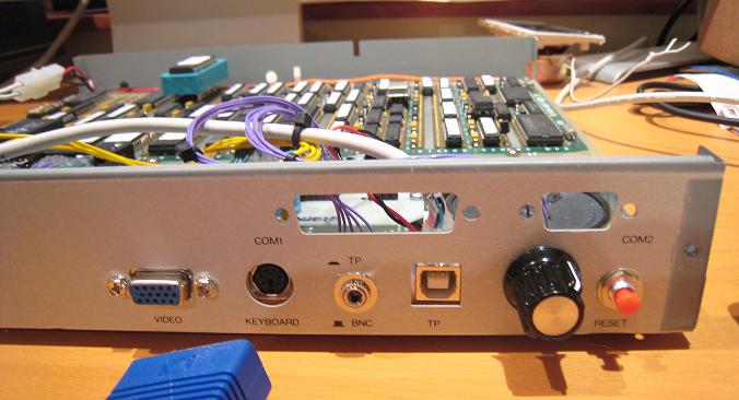
Here’s the rear of the case after installation of the DC power jack (in the space where the AC plug was originally), the VGA video connector, and the new reset button:
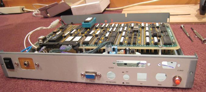
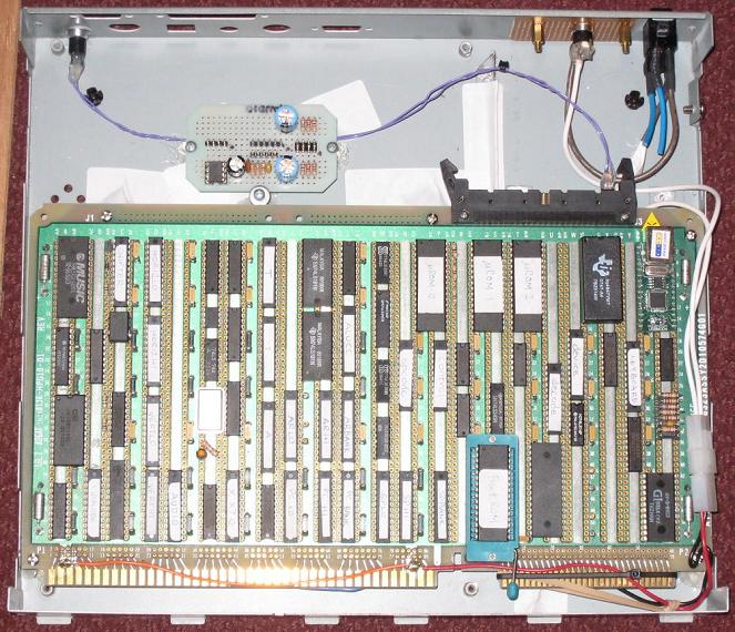
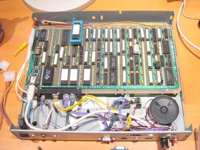
And here’s a top view of the same thing, showing the audio board installed, but no other components yet:
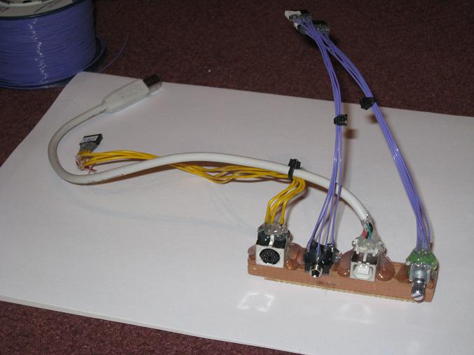
The hardest part was the rear port connectors. The headphone jack and volume knob are panel-mount connectors, but the keyboard and USB connectors are PCB-mount, and I didn’t have a PCB to mount them on. I need something to attach all the connectors to, to hold them in the right position relative to the holes in the case, and keep them sturdy enough to withstand the force of repeated pluggings and unpluggings. I ended up mounting the connectors on a piece of wood that was just the right height. The PCB-mount connectors were mounted upside-down on the wood, with the legs facing upward. That means the keyboard and USB connectors are upside-down, relative to how you’d see them on a normal PC. Odd, but not really a problem.
Here’s the finished rear port connector module. From left to right, it’s keyboard, headphone/line, USB, and volume. The connectors all run internally to jacks on the BMOW main board or audio board.
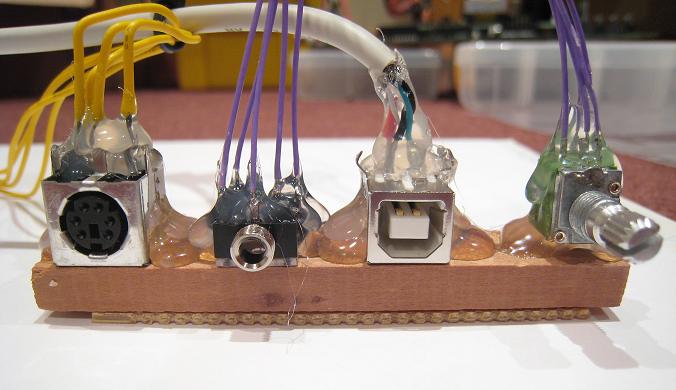
Here’s a close-up of the rear port connector module. There’s lots of hot glue poured over everything:
With everything crammed inside the case, including a small speaker, it’s a tight fit:
With the rear panel ports populated, it begins to look like a recognizable computer. I even found a retro-style volume knob. Who really cares if the USB port is actually labeled “TP”? Those vacant COM1/COM2 ports don’t look very nice, though. Ventillation holes?
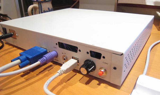
At this point, I tried to put the cover on, and discovered that it didn’t fit! What the $@#*&#? I had to get out the Dremel tool once more, to grind down a small metal fin that projects from the inside of the cover down into the case. After grinding it off, there’s only about 0.1 inch of clearance.
The finished product, with cover successfully installed:
Front view. I need to silkscreen a BMOW logo on there somehow:
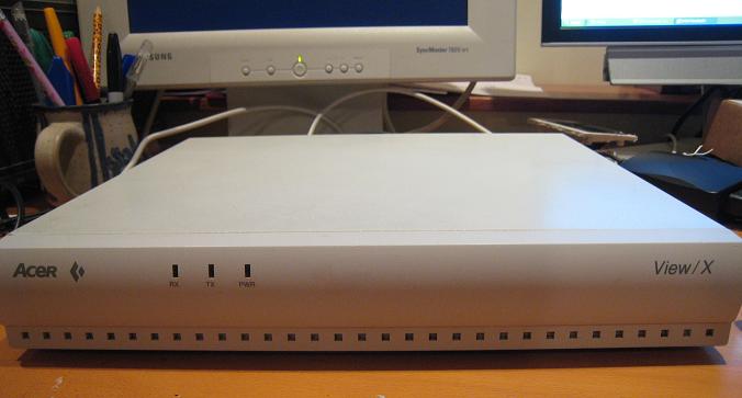
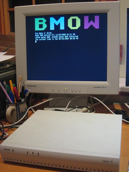
All this, and it still runs too:
That’s almost it for my hardware plans. I’d like to hook up those three LEDs on the front panel, and I’m probably going to cut an opening in the front to mount a 2-line LCD. Then I plan to tidy up the software a bit, and create a “demo ROM” with a menu of my greatest hits like animating kid photos, Microchess, BASIC, and music players. Then BMOW should be ready for its world tour, or a quiet retirement.
Read 8 comments and join the conversation8 Comments so far
Leave a reply. For customer support issues, please use the Customer Support link instead of writing comments.
Very cool.
You know, I just realized this. Those wirewrap boards are actually designed to fit into buses in actual cases designed just for wirewrap computers. Maybe for Son of BMOW you could invest in a wirewrap bus and a case to fit it and you could put the daughter cards on wirewrap boards too.
He’s right. Vector is still selling S100 Bus boards, and even matching cases.
But I am impressed. Now that you’ve got it built, you can go over what happened, and why you did that. And then create its Son, and promptly make the usual improvements.
Do I have an S100 board? It doesn’t look like the photos of S100’s I found. My board has two edge connectors with different lengths and contact spacings. Do you have a link to the Vector boards or cases? A Google search only turned up a computer made by Vector, not generic boards, backplanes, or cases.
Even if I had a case that was designed for this board, I’m not sure it would have helped too much. The majority of the work was building the cables and connectors for all the rear panel ports, which I assume I’d have to do in any event, unless the case included some kind of prebuilt I/O card.
I’m not sure BMOW will have a son. I think he’s a sworn bachelor.
That’s absolutely amazing. It’s incredible that you did a entire home made cpu by your own.
If you make it entirely open source surely you can get the project bigger.
I think you’ll find it’s a Multibus board.
http://www.classiccmp.org/hp/multibus/methode%20WW.jpg
The wire-wrap board that you’ve used looks to me like a Multibus board. It has two edge connectors on one side, one with wide fingers and the other with narrow fingers:
http://www.classiccmp.org/hp/multibus/multibus.html
Hmmm.
I believe I found my entries concerning Vector’s S100 family simply by tracking back through the news://comp.os.cpm listings.
I’ve got here an interesting behemoth who happens to be S100 based, and naturally I am interested in installing a WW board for the odd user-designed example.