

Uzebox
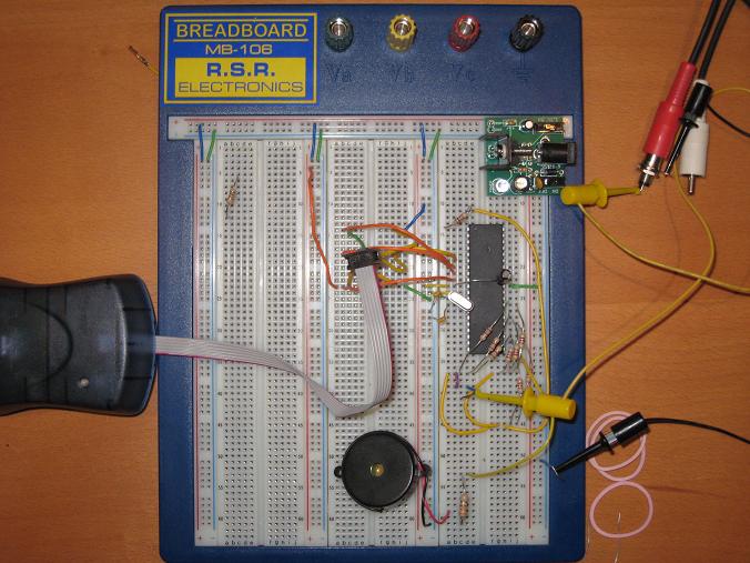
I’ve decided to build a minimal Uzebox. The Uzebox is a software-generated video game system based on an open source hardware design. It uses an ATMega644 microcontroller with 4K RAM to synthesize a composite video signal and sound on the fly, line by line. The official Uzebox design uses an Analog Devices AD725 RGB-to-composite chip, along with an SD card interface, and MIDI and joystick ports. I really wanted something super-minimal, though, so I dropped everything from the system except the ‘644 itself, the power supply, a piezo speaker, and some resistors and capacitors. I think it’s about as bare bones as you can get. Here’s what I came up with:
To replace the AD725 color chip, I constructed a grayscale binary weighted DAC from nine resistors. The eight color bits and the sync signal from the ‘644 are combined. I did some math to solve for the correct resistor values to produce 1 volt when all the colors bits are 1’s, and 0.3 volts when all the color bits are 0’s, assuming the sync signal is 1 in both cases. I must be getting dumber in my old age, because it took me a long time to churn through the math, and I eventually had to ask my wife to help. This was the result:
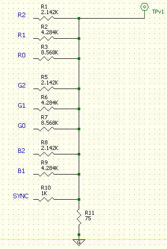
This seems right mathematically, but when I tried it connected to the TV, the resulting voltage was too low. When I removed the 75 Ohm resistor, everything looked nearly perfect. I don’t really understand that… should the video cable and TV itself be treated as a 75 Ohm resistor to ground in this calculation? Something about impedance matching that I don’t really grasp.
With the 75 Ohm resistor removed, I burned a Pac-Man game into the ‘644, connected the breadboard to the living room TV, and was rewarded with this:
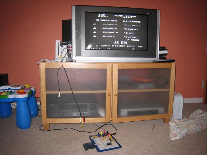
The image quality is middling, but it’s not too bad for a quick breadboard job. The grayscale is definitely working, although it’s hard to see in this picture. The ghosts show the grayscale levels best.
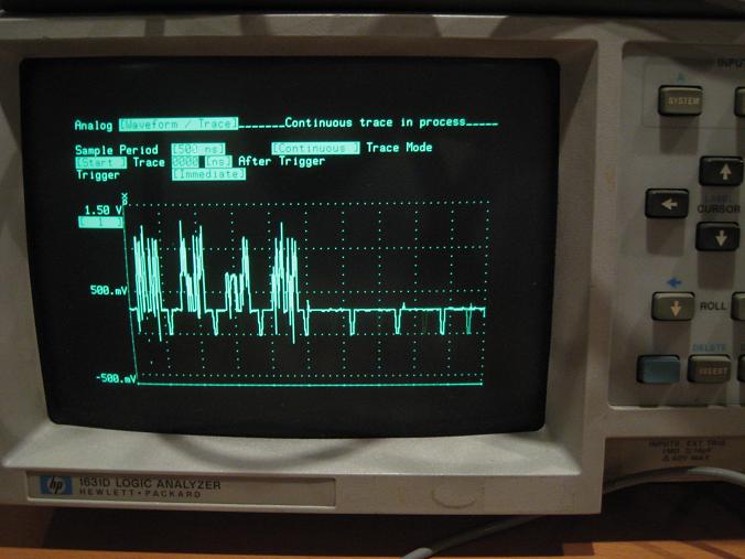
Unfortunately I couldn’t get the Uzebox to work with the composite video input on my Dell monitor. It didn’t show anything at all, behaving the same as if nothing was even plugged in. I’m assuming this is because my video signal is too noisy, or out of spec somehow, and the monitor is more picky about signal quality than the TV. I looked at the video signal on the oscilloscope, though, and it looks pretty decent to me. Not too much noise, baseline is right at 0.3 volts, HSYNC pulses look fine. The brightest parts of the image do overshoot to about 1.25 volts, but I wouldn’t guess that would be a huge problem. I need to find a solution, though, because hauling the whole thing into the living room for every test isn’t too practical.
Although my interest here is primarily in the hardware, it’s damn impressive that this single ATMega644 with just 4K RAM is able to generate all the video and audio for a very faithful Pac-Man recreation. Remember, there’s no frame buffer. The video signal is generated on the fly, line by line, pixel by pixel, in the midst of all the other necessary game-related computation.
Read 12 comments and join the conversation12 Comments so far
Leave a reply. For customer support issues, please use the Customer Support link instead of writing comments.
Yes, the video cable is expected to have a 75 ohm impedance and so the tv/monitor is designed to match this impedance. If the impedances don’t match, a portion of the signal will be reflected (and if reflected again at the source side of the cable it will show up in the picture as a faint ghost image slightly to the right of the original). Ideally your circuit should also have a 75 ohm source impedance. I’ve seen some circuits use an op-amp (with a large enough gain bandwidth product to handle a video signal) configured for a gain of 2 connect to the video cable through a 75 ohm resistor to give the proper source impedance. This 75 ohm resistance in conjunction with the 75 ohm impedance of the tv/monitor form a voltage divider with a factor of 1/2, to give an overall unity gain. I used to know why we can ignore the impedance of the video cable itself for this part of the analysis, but it eludes me at the moment.
From your picture, it looks like there are occasionally pulses below 0.3 V during the active video in between the sync pulses. Perhaps your Dell monitor is seeing these also as sync pulses and then decides that this can’t be a valid video signal since the sync pulses aren’t coming in at the expected rate.
I think the problem may be that the video signal has a DC offset. Perhaps you should try AC coupling it, though you’d need to revise your output slightly to do it.
Alternatively, you could try removing the offset so the black level becomes 0V instead of 300mV. This would require a negative supply, which is a pain.
Ah, I think you’re both right. Somehow I didn’t even notice the spikes below the 0.3 volts during lines. I’ll need to look at that further… that should be impossible given the DAC, unless the sync signal itself goes low during that time.
Merlin, isn’t the video signal supposed to have a DC offset? The reference I used showed a baseline black level of 0.3 volts, sync pulses at 0 volts, and line intensity as high as 0.1 volts. I could easily stick a capacitor inline, which I think would shift everything down by 0.3 volts.
WOW!
I am impressed so far. It indeed a starting point.
And yes I recall from going over that particular issue in the Lancaster book on Television Typewriters, a 75Ohm impedance is needed to balance the odd display who also has one on its end.
OK, I revisited the grayscale DAC, this time accounting for the 75 ohm impedence of the TV itself. It works out that all the resistor values in the schematic I posted above just need to be halved. Now I get the correct voltages, *with* the 75 ohm termination resistor in place, which is good.
Unfortunately, it still doesn’t work on my Dell monitor. I looked more closely at the signal using a smaller timescale, and there’s a ton of overshoot and undershoot. In the middle of a scan line, when the signal is at white (1 volt) and returns to black (0.3 volts), it actually shoots down to almost 0 volts for 10-20 ns before recovering to 0.3 volts. The opposite problem happens on black to white transitions, where the voltage overshoots 1V and reach about 1.3V. I’m guessing that the Dell monitor sees the undershoots as false sync pulses, and gets confused.
I’m not really sure how I can fix this. How do you cure under/overshoot? It seems to point to an impedance matching problem again. I also tried adding an RC low-pass filter to smooth out the signal a little and eliminate the under/overshoot, but I couldn’t get it to work. By the time the under/overshoot was substantially reduced, the whole signal had been turned to mush. It’s quite possible I constructed the filter incorrectly, or measured wrong, because that doesn’t make a whole lot of sense to me.
A couple of references I just found do indeed imply a DC offset, but experience tells me that these things are usually AC coupled. At least it would be easy to try, but you will need a big capacitor (say 1000uF) to make the impedance low compared to the 75 Ohm load. You might consider having a small ceramic capacitor in parallel with it to improve the high-frequency response.
I don’t think the transients are due to impedance problems. Can you be sure that the outputs to the DAC change simultaneously? If not, you could be seeing transient errant values which the DAC is faithfully turning into output spikes.
Another fix may be some kind of sample-and-hold circuit. This would sample the output a short time after each change, thereby ignoring the transients. This would be tricky to implement, though.
Regarding impedance, it is not really the cable that is presenting the 75 Ohm load – at least not most of the time. The TV will have a terminating (75 Ohm) resistor in it. You should be able to “see” it with a DMM across the input. The tricky bit is that there is a significant time during which each video signal level change has to travel down the cable (at very roughly 0.5 feet per ns). During this time, the TV hasn’t seen the signal yet, but your circuit “sees” the effect (impedance) of the cable. With a properly matched 75 Ohm cable, your circuit drives the 75 Ohm cable, and then the 75 Ohm terminator resistor when the signal reaches the TV. To the source, these look identical. Anything else, as said before, will cause reflections. These can bounce up and down the cable, causing various bad effects.
This is known as transmission line theory, and you will find loads of information on the internet if you have a look. It applies very much to backplane design as well, for all the same reasons. For really short cables, it doesn’t matter much, but as the cable becomes longer the effects are very much more noticeable.
Sorry – this has become rather long. I hope at least some of it helps!
That 10-20 ns low period when you go from white (all outputs on) to black (all outputs off) sounds a lot like ground bounce to me.
At peak white there is around 13ma flowing through your local 75 Ohm resistor, which drops in a few nanoseconds to 4ma. Unless you have good decoupling at the power pins of the ATMega644, and a good ground plane (ok, maybe not on a protoboard!) then you will probably suffer these glitches.
From the photo it looks like you have an electrolytic across the power pins. I would stick a 100nF ceramic across there too, and see if that improves matters.
Good luck!
Sorry, forgot to add that you should check where the ground end of your 75 Ohm resistor is too. Ideally it should be very close to the ground pin on the ATMega644.
Good point. I’d definitely try David’s idea first!
Merlin
Bah. I spent a frankly ridiculous amount of time fiddling around with the circuit, changing capacitors, changing resistors, moving wires, impedance matched, not matched, you name it. I managed to clean up the signal quite a bit. I also found schematics for five similar projects on the web, and checked them to make sure I’m not doing something stupid. Nothing would make the Dell monitor work, not even flicker for a moment or show same garbage. It was just nothing, totally dead, when I connected my circuit.
I’ve finally reached the conclusion that my voltages are OK, and it’s the timing that the Dell monitor doesn’t like. This is actually the first thing that the Uzebox’s designer suggested. The Uzebox generates a non-interlaced composite video signal with only 524 lines per frame instead of 525. Unfortunately I don’t have any simple way of confirming this, and changing the Uzebox timing isn’t really practical. Since I don’t have another composite video screen in my work area, I think this pretty much ends my Uzebox experiments. Darn.
How did you do the math on the DAC again? Could you please explain how you derived those resistor values? Thanks.
I wish I remembered exactly how I derived the resistor values. I knew I needed to produce 1 volt when all the colors bits are 1’s, and 0.3 volts when all the color bits are 0’s, assuming the sync signal is 1 in both cases. I also knew R1:R2:R3 needed to be in the ratio 1:2:4 in order to get the correct binary weighting. Ditto R5:R6:R7. There is no least-significant bit for blue, so only two resistors there. So in the end I knew there would be 9 resistors with values X, 2X, 4X, X, 2X, 4X, X, 2X, and Y, with Y being the sync resistor. Two equations, two unknowns, solve for X and Y.