

Experimental Hardware
With the design of the Tiny CPU core more or less finished, I’ve started thinking about how to build a small computer around it. My goal is to create a simple machine with a keyboard input, a 4-line LCD output, and a few buttons and LEDs for debugging. Everything should be mounted on a custom PCB that I’ll design as well.
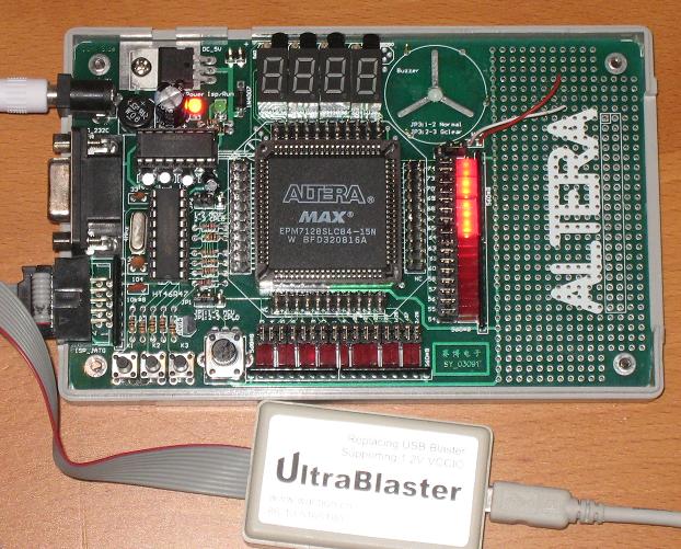
I’ve purchased an Altera USB-Blaster, and a CPLD prototyping board containing the same CPLD model that I plan to use. This will let me see exactly how someone else built a working system around this device, and give me something to compare to when my own machine inevitably fails to even turn on after it’s built. I can also add a few components to the prototyping board, to try out a scaled-back version of the computer design before I commit to manufacturing my custom PCB.
The documentation with this board was pretty sparse, and the USB-Blaster clone had none at all, but after a little work I managed to figure it out. I’ve been able to reprogram the CPLD on the board, and do a few basic LED blinking types of tests. If I get motivated, I may try to fit a RAM, ROM, and a few other parts in that empty area on the right, and see what I can do.
For the ultimate Tiny CPU PCB, even for a “simple” system, there are going to be quite a lot of components. Assuming I use the free version of Eagle for the PCB layout, with its 10cm x 8cm area limit, I may need to stack two or even three boards to get everything in. The semi-final parts list is:
- CPLD #1 – for the Tiny CPU
- CPLD #2 – for address decoding, LCD interface, keyboard interface, etc
- ROM (in a ZIF socket, or maybe a JTAG-programmable ROM)
- RAM
- clock oscillator
- DC power jack
- voltage regulator
- reverse voltage protection diode
- capacitors for voltage regulator
- PS2 keyboard jack
- pull-up resistor for keyboard clock
- Shottky inverter for keyboard clock, to address very slow slew rate (based on BMOW experience)
- LCD connector header
- resistor for LCD backlight
- variable resistor for LCD contrast
- piezo beeper
- variable resistor for volume
- transistor for piezo power
- 7-segment LED
- current-limiting resistors for 7-segment LED
- reset button
- pull-up resistor for reset button
- power LED
- current-limiting resistor for power LED
- on/off switch
- rotary encoder
- push button
- ISP/JTAG header (connnect both CPLDs into a JTAG chain)
- RC reset circuit
- debug headers
That’s a lot of stuff to fit into 80 cm^2. For comparison, the board in the photo above is about 126 cm^2, but contains less hardware than what I think I’ll need.
Read 7 comments and join the conversation7 Comments so far
Leave a reply. For customer support issues, please use the Customer Support link instead of writing comments.
So cool that the prototyping board comes with a propeller (next to the 7-segment LEDs). Pity that it’s not closer to the center of gravity — the board will only fly at an angle. Sigh.
Rotary encoder?
Nah, you just need a trim adjustment to get straight and level flight.
The rotary encoder is a backup input device, not really necessary, but handy. The FPGA starter kit I used for 3D Graphics Thingy has one, and was easy to use. http://en.wikipedia.org/wiki/Rotary_encoder#Incremental_rotary_encoder
Why not use kicad instead of eagle? It is GPL, allows unlimited board size, and is pretty good overall.
I’ve done ~10 board designs with kicad (both 2 and 4 layer), and think it is pretty good.
That’s an idea, but I know virtually nothing about Kicad. Do you think it would be up to the task? Almost all of the hobbyist PCB designs I’ve found online have been done with Eagle, which tells me that people judge it the right tool for the job. Sparkfun also pushes it, for all their hobby stuff.
I expect the most important features for me will be availability of component footprints (or ease of making custom ones), quality of auto-routing, and overall ease of use for someone who’s never done this before.
See http://store.curiousinventor.com/guides/kicad
for a tutorial for an earlier kicad version.
Designing packages is easy, though it has a library that comes with it. I normally design my own footprints from scratch using datasheet info for anything not an ultra standard DIP or 603, etc.
I cannot speak for kicad’s auto-routing as I have always manually routed boards (up to ~1k+ pads). I’ve never seen an autorouter output that I like.
There does seem to be a lot of inertia for eagle in the hobbyist market, but I’ve done some pretty crazy stuff with kicad and feel it can handle about everything.
I think if kicad had been around earlier eagle would never have gotten its foothold.
It’s exciting to see your hands-on approach with the CPLD prototyping board and USB-Blaster. I’m curious, which challenges do you anticipate most when scaling up from a single prototyping board to your full Tiny CPU PCB? Also, how do you plan to test the integration of RAM, ROM, and other components safely?