

In-System CPLD Programming Using XSVF Files
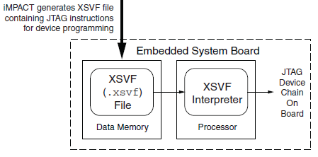
Floppy Emu has both a microcontroller and a CPLD working in tandem, and both must be programmed in order for the emulator to function. However, I don’t want to require two separate external programmers and the associated port connectors. My plan is to use a standard external ISP programmer for the microcontroller, but have the microcontroller program the CPLD, using the technique described in Xilinx app note XAPP058. The idea is to have the microcontroller act as an XSVF player, loading the CPLD configuration file from the SD memory card, and bit-banging the four JTAG pins on the CPLD to perform the programming.
This week, I finally got around to working on the XSVF player so I could program the CPLD on the Floppy Emu prototype board. The Xilinx player sample code is written in C, and was fairly easy to integrate into the emulator program. Using the functions I’d previously implemented, it was quick work to add an option to load a config file from the card and execute it with the XSVF player.
Predictably, once all the pieces were in place, it didn’t work. I spent a while checking and re-checking all my assumptions, reviewing the code, and writing debug info to the LCD, but made no progress. Finally I used the oscilloscope to peek at the JTAG signals, and discovered that they weren’t wiggling at all. All four JTAG signals were stuck high. I spent a few more hours chasing various theories why that might happen, and double-checked the electrical connectivity, before I gave up to do something else. Immediately after leaving the room, I suddenly realized what the problem was: in order to programmatically control the microcontroller JTAG pins, the JTAGEN fuse must be turned off, to disable hardware JTAG. Once I did that, the signals began wiggling as expected when I ran the XSVF player.
At this point the outgoing TMS, TCK, and TDI signals looked reasonable, but the JTAG communication still didn’t work. The error code from the player indicated that the TDO data returned from the CPLD didn’t match what was expected. Again the scope proved useful, this time by showing that TDO was stuck low, and never changed its value. No wonder the data didn’t match what was expected– it was always zero.
Here’s where I would normally describe how I finally solved the problem and got everything working, except this time I didn’t. At this moment TDO is still stuck low, and CPLD programming or other JTAG communication is not possible. I’ve examined the TMS, TCK, and TDI signals, and they look reasonable, and appear to roughly match the output of the PC-based XSVF player simulator that’s part of the Xilinx sample. So what might be wrong? Some theories, none of them great:
- The CPLD’s JTAG controller might not be active. But according to the datasheet, “If the device is in the erased state (before any user pattern is programmed), … the JTAG pins are enabled to allow the device to be programmed at any time. All devices are shipped in the erased state from the factory.”
- The JTAG controller might be in the wrong state to respond to the commands from the XSVF player. However, I looked at the code, and the first thing it does is reset the controller (by setting TMS high and pulsing TCK five times). This should be OK.
- The communication from the XSVF player might be garbled or broken. Maybe I accidentally swapped two signals, or introduced a bug in the player code? My preliminary scope debugging shows the signals look OK, so I’m skeptical this is the problem.
- The JTAG clock might be too fast. Initially the player code resulted in a JTAG clock rate around 500 kHz. I tried slowing it to under 1 KHz with no success.
- The player might not be waiting long enough for CPLD internal operations to complete. There’s a fairly long discussion of this in the sample code, and I’m fairly sure I did it correctly. When I tried slowing down the player even further, it didn’t help.
- The XSVF file might be bad. I’m using a file I generated with Xilinx iMPACT, which should simply query the device ID, then terminate.
- There might be an electrical short between TDO and ground. I’m fairly certain this isn’t the case, because before I disabled microcontroller’s JTAGEN fuse, TDO was about 4.5 volts. Now it’s zero. If there were a short to ground, it would have always been zero.
- The CPLD might be installed backwards or rotated, so the board trace isn’t actually connected to the TDO pin. I double-checked the orientation, and it looks correct.
- The CPLD might be damaged or defective.
For the moment at least, I’m stumped. I’m out of ideas for other things to try. I’m going to set this aside for a while, and hope that the solution will suddenly occur to me while I’m working on something else. Or failing that, I may at least come up with new theories that can be tested. Debugging electronics sure can be a pain!
Read 8 comments and join the conversation8 Comments so far
Leave a reply. For customer support issues, please use the Customer Support link instead of writing comments.
I thought of one more possibility: after disabling the microcontroller’s JTAGEN fuse, the TDO pin in might have been inadvertently configured as an output driving 0, instead of an input. That would cause contention if both the microcontroller and the CPLD tried to drive different values. I’ll double check this.
I am not 100% sure on this. (Never really worked with JTAG, certainly not my own pcb)
swapping tdi and tdo could possibly cause the problem. try swapping the pins you are using and see if it works.
I do know that the ft2232H and friends requires TDI on it connected to TDI on the device. I also made the mistake of “doing the logical thing” and connected tdi to tdo on a design that I scrapped for other reasons.
I thought I had mostly gotten over my serial dyslexia.
Did you say you are using the microcomtroller’s JTAG pins to connect to the CPLD JTAG pins? I’m assuming so since you had to disable the JTAG hw fuse in the micro. I suspect Alex is on to something with swapping TDI and TDO.
Swapped TDI/TDO is a good thought, and is actually half-true, but I don’t think it’s the problem here. It’s true that I connected the CPLD’s TDO to the micro’s TDO, and TDI to TDI, which would be wrong if I were trying to form a JTAG chain containing both devices. But with the JTAGEN fuse disabled, the micro’s pins become general purpose IOs, so it doesn’t matter where the signals are connected. I’m reading the TDO from the CPLD, which is definitely its JTAG output, so the connections are correct as far as I can see.
I enabled the micro’s weak pull-up resistor on TDO, and now it reads 5V. That means the CPLD isn’t actively driving TDO at all, so it’s just floating. Hmmm.
Good news. It seems that something was wrong with the XSVF file I was using for testing. The test file just queries the device ID, but it always fails. I tried using a real XSVF file that configures the CPLD with a simple LED-blinker design, and it works!
Good to hear
Good news. It seems that something was wrong with the XSVF file I was using for testing.