

Wire Wrapping the Nibbler CPU
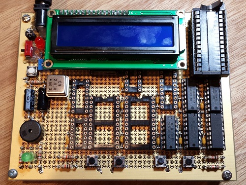
Nibbler construction is underway! I’m building the CPU on a 5 x 4 inch perfboard, and connecting the components using wire wrap. This particular perfboard is a Twin Industries 8200 Series, which has continuous metal planes on both sides that can be used for power and ground. Because the holes don’t go all the way to the edges of the board, the usable area is just 4.5 x 3.5 inches (114 x 89 mm) – about the same size as my mobile phone. It’s very compact. There’s enough extra space for two more 0.3 inch chips, if I later decide to add to the system.
Unfortunately construction didn’t start smoothly. The board didn’t have any mounting holes, and you can see in the photo what a lousy job I did trying to drill four evenly-spaced holes in the corners. After drilling, I made legs by putting screws through the top into 1 inch aluminum standoffs underneath. I quickly discovered that top-side screws in bottom-side standoffs formed an electrical connection, shorting the ground and power planes! Ugh. Inserting nylon washers between the standoffs and the bottom of the board solved that problem, but it wasn’t the last of the challenges.
These kinds of boards are great for mounting and connecting DIP chips, but not so great for anything else like discrete components or buttons. Anything that doesn’t have 0.1 inch spaced pins requires bending or drilling, and discretes also require soldering instead of wire wrap. It took me several hours to drill holes for the DC power jack, deform the button pins to a 0.1 inch spacing, and mount and solder all the other passive components. In many cases that involved cutting a wire so it could be soldered at one end, but wrapped at the other end. What a pain in the butt.
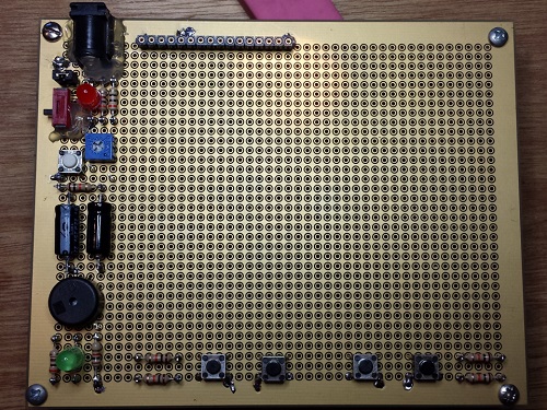
After placement of the discrete components
Soldering anything to this board is surprisingly hard. Each hole is separated from the plane that surrounds it by a circular ring of soldermask. In order to connect a discrete component’s pin to the power or ground planes, the solder must bridge across this ring, and that’s something the solder definitely doesn’t like to do. More and more solder must be added, until it suddenly flows across the ring *and* into the neighboring hole, creating an accidental short. Grrrr! With practice I was able to avoid this, but each solder point was a trial of patience.
After placing all the discrete components, I did a trial fit of all the wire wrap sockets, mounting all the chips inside them. It’s a good thing I did, because there were clearance problems all over the place! If I’d wired up half the system before discovering the clearance issues, I would have been in big trouble. The worst problem was the 74HCT74 for Phase and Reset. Although it’s a 14-pin chip, its package is so elongated, it actually needs more room than other 16-pin chips! I also found a few vertical clearance problems. The LCD is supposed to sit on top of several chips, but I discovered there wasn’t as much space as I’d expected available under the LCD. I’m going to have to build some kind of vertical extension for the LCD, in order to raise it high enough to clear the chips under it.
The last big hurdle was the ZIF socket for the program ROM. I know from past experience that I’ll be swapping that ROM in and out frequently, and I don’t want to have to use a chip puller each time. A ZIF socket will solve the problem, but wire wrap ZIF sockets don’t exist, or are so rare that it amounts to the same thing. I ended up soldering a standard ZIF socket to two rows of machine pin male header, and then inserting the header into a wire wrap socket. It’s not pretty, and the socket sandwich is more than an inch tall, but it works!
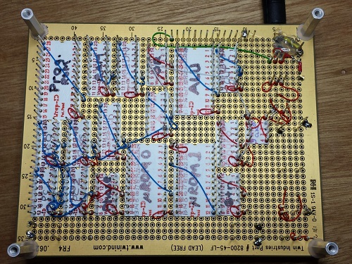
The wiring side, after placement of the power, ground, and clock lines
No comments yet. Be the first.
Leave a reply. For customer support issues, please use the Customer Support link instead of writing comments.