

Emulating the Apple HD20
The Apple Hard Disk 20 (HD20) was an external 20 MB hard drive for the Macintosh, introduced in 1985. This was during the earliest days of the Mac’s history, before the introduction of SCSI support, so the HD20 connected to the Mac’s floppy port. Despite sharing the same DB-19 connector as a floppy drive, the HD20 used an entirely different communication method, making it something of a hardware freak. When SCSI support was introduced in 1986, external hard drive solutions quickly adopted the new standard, and the HD20 faded into obscurity.
During the long course of Floppy Emu’s development, several people have suggested that it might be possible to emulate the HD20 using the same hardware. In theory it should only require changes to the CPLD and AVR firmware, since the HD20 uses the same physical interface with the same pins as a floppy drive. But in practice, no documentation of the HD20 communication protocol existed, and reverse engineering it looked to be such a daunting task that it wasn’t worth it.
Circumstances changed last fall, when a couple of HD20 specification documents surfaced on the internet. Who knows where they came from – probably rescued from the bottom drawer of an ex-Apple engineer’s desk in a questionable release of company confidential information. But it’s hard to imagine anyone getting upset over documents nearly 30 years old, detailing a long obsolete peripheral for a long obsolete computer. The two most interesting documents are the specifications for “directly connected disks”, one dated March 1985 and a later revision dated May 1985. The DCD standard was planned to support a variety of device types, but ultimately the HD20 was the only product to ever use it. With these two documents and a careful examination of the HD20 driver routines contained in the Mac’s ROM, it looked like it might finally be possible to emulate the HD20.
Into the Abyss
So how does it work? First off, we can assume that raw data bytes are sent and received in serial fashion using NRZI encoding on the ReadData and WriteData lines of the floppy connector. While the DCD documents don’t specifically mention this anywhere, it’s a safe assumption because the floppy interface is powered by the Mac’s IWM chip (Integrated Wozniak Machine), which is hard-wired to send and receive data this way. So the main questions surround exactly what data bytes are sent and received, and when, and how the other lines on the floppy connector are used.
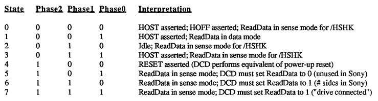
The DCD docs describe a state-based protocol that’s mercifully straightforward, compared to the oddities of the floppy drive interface. The Phase0, Phase1, and Phase2 lines on the floppy connector (sometimes called CA0, CA1, CA2) are used as a 3-bit state ID, to control the workings of a state machine governing Mac to DCD communications. At boot up, the Mac cycles through states 6, 7, and 5 in that order, checking the value on the ReadData line after each state transition. If it sees the values 1, 1, and 0, then it concludes that a DCD is connected to the floppy port, rather than a standard floppy drive.
HD20 communication is always a two-way exchange, with a command from the Mac followed by a response from the drive. From state 2 (idle), the Mac transitions to state 3 to indicate it wants to send a command. Seeing this, the DCD pulls /HSHK (the ReadData line) low to indicate that it’s ready to receive the command. The Mac then transitions to state 1 and sends the command, after which it transitions to state 3 to signal that it’s done. The DCD then brings /HSHK high again to acknowledge the end of the transfer, after which the Mac transitions back to the idle state.
When the DCD is ready to send a reply, while in the idle state, it pulls /HSHK low to indicate that it wants to send. The Mac then switches to state 1, and the DCD sends the reply bytes. After the last byte, the DCD brings /HSHK high again, and the Mac transitions back to the idle state.
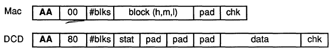
Commands follow a fairly simple structure. A read command and response are shown above. The command begins with $AA, which functions as a sync byte and start of command marker. The next byte is the command id. In this case, $00 means it’s a read command. Following that are the number of 512-byte blocks to read, a three byte block address, a padding byte, and a checksum.
The reply looks similar to the command. Again there’s an $AA sync byte, followed by the command id. The command id in the reply is always the command id from the request plus $80, though I’m not sure the reason for this. After that is the sequence number of the block being sent, a status byte (zero means OK), more padding, the actual block data, and a checksum.
The HD20 carries over the concept of tag bytes that originated with the Apple Lisa, and that are also present (but unused) on Macintosh floppies. Each block has 20 tag bytes, so from a low-level point of view, blocks are essentially 532 bytes instead of 512, and 532 bytes of data will be returned in reply to a read request. The Mac throws away the 20 tag bytes, however, and only the last 512 bytes are treated as disk data. From the point of view of an emulator, only those 512 bytes need to be filled from a disk image file, and 20 bytes of zeroes can be prepended for the tags.
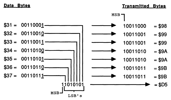
Because of the way the IWM works, the MSB of every transmitted byte must always be 1, so in effect there are only seven usable bits per transmitted byte. The DCD standard uses a 7-to-8 technique in which data is collected into groups of seven bytes, and then repackaged and transmitted as eight bytes with an MSB of 1 for every byte. This technique right shifts each of the seven bytes by one bit, chopping off the LSB, and setting the MSB to one. Then all of the chopped off LSBs are collected into an 8th byte. At the other end of the line, the receiver applies the reverse process to recover the original seven data bytes.
From Theory to Practice
That’s how it’s supposed to work, anyway, but there are many gaps and inconsistencies in the documents. One of the biggest concerns is that the March version of the doc differs in major ways from the May version. For example, the handshaking method described in the March doc is completely different than what I described in the previous section, based on the May doc. If there was that much change in the space of two months, it’s likely that the spec continued to evolve after that, and the May doc may not reflect the final version as it was eventually implemented.
Some important details just aren’t mentioned at all. What’s the checksum algorithm used? Nobody knows. An appendix also mentions a couple of dozen diagnostic commands, without describing what the parameters mean, or how the DCD should reply. Answering these kinds of questions requires a combination of educated guesswork, experimentation, and good old reverse engineering.
The code used by the Mac to communicate with the HD20 is contained in the ROM of the Mac Plus and other early Macs. Unfortunately this is raw 68000 machine language, so it’s difficult to read and understand what it’s doing. With the help of disassembler tools, the ROM data can be converted into 68000 assembly mnemonics, and symbolic names can be substituted for some known memory addresses, resulting in a code listing like this one:
L4772: MoveQ.L $4, D0
L4773: DBF D0, L4773
       Move.L D6, D0
       Add.L $810081, D0
       Move.B $-56, $400(A0)
L4774: Tst.B (A3)
       BPL L4774
       Move.B D0, (A0)
       Swap D0
L4775: Tst.B (A3)
       BPL L4775
       Move.B D0, (A0)
That’s not very instructive. But after long hours of studying and examining other nearby sections of code, some sense of structure does slowly emerge. For example, from looking at where A3 is set previously, I can tell that those Tst.B (A3) instructions are checking to see if the IWM is busy. And the Move.B D0, (A0) instructions are each writing a new byte to the IWM. Other clues are provided by the literal value $-56 appearing in the code, which when expressed as an unsigned byte is $AA – the sync byte. So what we have here is something that does a short busy loop, then adds $810081 to an unknown value from D6, and stores the 32 bit result in D0. Then it writes the $AA sync byte, waits for the IWM, writes the low byte of D0, waits for the IWM, and writes the high byte of D0. So it looks like it’s the preamble to sending a command to the DCD.
This is the kind of “deep in the weeds” analysis that’s needed to fill in the blanks for an emulation project. It’s something I’ve spent a lot of time doing for Floppy Emu and for Plus Too before that, so I’ve gotten pretty good at it, but I can’t really say it’s fun.
And a Progress Report
Armed with all this information, I began by hacking up the firmware on a Floppy Emu to identify itself as a DCD, and observe the proper handshaking rules for the various states. No data was actually sent or received. That was enough to get a noticeable reaction from the Mac: at bootup it froze for a long time, then when it finally did boot (from a SCSI drive), it complained that an attached disk was uninitialized and needed to be formatted. Then I wrote a simple test program to read arbitrary blocks from the DCD. The program always reported error -17 (driver can’t respond to this call). That was logical, but a little disappointing, as I could see from the ROM disassembly that there were many other more specific error codes that might be returned to give better feedback on what was and wasn’t working. I was hoping I might get an error like 64, no response received, or 33, timeout waiting for sync byte.
I spent a while tinkering with things, trying to get a more specific error than -17, but without success. I also tried using MacsBug to debug the HD20 driver routines while they were executing, but that appeared to create some new timing-related problems that messed things up even worse. Finally I decided to change course, and attack the other end of the problem by looking at what was happening on the Floppy Emu when the error -17 occurred.
I started with just displaying the current state number on the Floppy Emu LCD. I could see it go through states 6, 7, and 5 at bootup, just as the docs say it should. Then it went through states 2, 3, 1, 3, and 2, which looked like an attempted Mac to DCD command transmission. That seemed promising, so I leveraged the existing write code for Floppy Emu to try to collect the data bytes sent by the Mac, and display them on the LCD. That’s when I got the first payoff, as the received bytes were:
AA 81 B1 C1 81 80 80 80 80 80 FE
There was the $AA sync byte. And if you looked at the last eight bytes (beginning with $C1), it looked like a valid 7-to-8 encoding. Decoding those bytes yielded:
03 00 00 00 00 00 FD
That was command id 3 (drive status, according to the doc), with a bunch of padding and a checksum of FD. The sum of all the bytes mod 256 was 00, so that’s likely the checksum algorithm.
But wait, what were the second and third bytes for, 81 B1? Those shouldn’t have been there, according to the doc. Help! Truthfully I’m still not sure what those are, but after long examination of the ROM routines, I’m about 90% sure the first byte is the size of the data being sent, and the second byte is the size of the expected reply. Both sizes are expressed as a number of 7 byte groupings, then added to $81. In fact, the code that outputs those two bytes is the snippet I analyzed in the previous section.
So for the example above, the size of the data being sent was zero (no data payload for a drive status command), and the size of the expected reply was $30 groups of 7, or 336 bytes. Probably these size bytes were added to the DCD protocol late in the development process in an attempt to provide some amount of forward compatibility, so a device could gracefully handle an unknown command and send back a dummy reply of the correct size.
That’s where things stand today. With a little more experimentation, I’m hoping I can send back a valid drive status reply, or at least one that’s close enough to generate a more specific error code than -17. Then things will start to get very interesting.
Read 12 comments and join the conversation
12 Comments so far
Leave a reply. For customer support issues, please use the Customer Support link instead of writing comments.
Great work!! It’d be useful to feed my old 512k 😉
[off topic]
The Macintosh Floppy Emu you ship to me works flawlessly, I plan to build a wooden housing case for it some day…
Wow, this is awesome. I was already seriously considering buying a Floppy Emu but if you can get HD20 emulation working I’m sold – I have a couple of 512kes sitting here which could use some reasonably-sized storage.
Have you seen this? It’s the IWM specification.
http://www.brutaldeluxe.fr/documentation/iwm/apple2_IWM_Spec_Rev19_1982.pdf
well hopefully you and doug can make some sense of this.
if there is anything that you would like me to try with my hd20 here let me know.
Wow! Sounds great esp. when I just bought my Floppy Emu 😀
p.s. a bit sad when I read about the v1.2 because I just received my now-older-version… and I think I will wait for the v1.3 again 😀
Don’t be sad: there’s no functional difference between 1.1 and 1.2.
this is exciting!!! thank you Steve!
Awesome information!
Any further updates?
😉
No further updates… to be candid, I’ve lost interest. I’ll probably return to it eventually, as seems to be the cycle with my projects!
Do you have a HD20? if not then maybe leverage your floppy emu clients email list to borrow one 😛
reverse engineering is tons easier if you can dump traffic with logic analyser, not to mention you can start emulating immediately by replaying back the dump and working your way up one byte at a time
I don’t have an HD20, but a few generous people have offered to loan me one. That’s not really the issue, though, at least not yet. I think I know roughly how to proceed, based on the docs I found and disassembly of the relevant code, but it’s a big complex task I just haven’t found the enthusiasm to pursue further since the time I did the original research into it. Someday, I hope…
See these newer posts for updates on HD20 emulation using the Floppy Emu hardware:
http://www.bigmessowires.com/2014/11/22/reverse-engineering-the-hd20/
http://www.bigmessowires.com/2014/11/25/hd20-firmware-0-1/
http://www.bigmessowires.com/2014/11/26/hd20-firmware-0-2-fewer-bugs-more-emus/