

How to Manufacture a Widget
So you’ve designed an electronic gizmo, it works nicely, and the public wants to buy it. You’ve built one, or ten, or a hundred by hand until your soldering iron wore out, and now you’re ready to have the gizmo manufactured in a low-volume production run. Where do you go, and how do you get started? This is where I stand today with my Floppy Emu project, and I’ve spent the past few weeks researching the answers.
Step one is identifying and contacting potential manufacturers. This is harder than it looks! Electronics manufacturers generally don’t deal with “the public”, and you can’t just browse listings on amazon.com. Many of them seem to be semi-anonymous, with generic-sounding names like Electronic Systems, Inc. From my experience, the best way to find manufacturing candidates is to ask everyone you know for referrals. Dropping the name of a current client may also help make a manufacturer more willing to work with you.
If you’re an inexperienced one-person team looking for a production run of 50 or 100 units, be aware that most manufacturers won’t talk to you. They won’t even bother to reply when you contact them – you’re just not worth their time. Don’t be offended, just move on.
Somebody Set Up Us the BOM
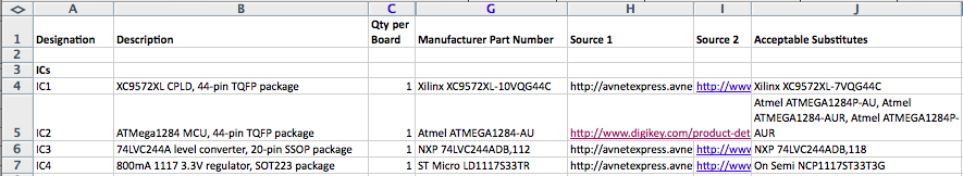
You can increase your chances of a favorable reply by being informed and organized when talking with the manufacturer. Have your Eagle/KiCad files and Gerbers ready to provide if requested. Make sure every part in your design is clearly identified with a designator like UC2 or R2, both in the design files and printed on the board itself. And most importantly, provide a detailed bill of materials (BOM) that defines exactly what part goes at UC3, R2, and everywhere else. If there are some footprints on the board that should be left empty, list those too. The more detail, the better.
Poor BOM:
- UC3 – ATMEGA1284P
- R2 – 220 Ohm resistor
- SW1 – push-button switch
Better BOM:
- UC3 – Atmel ATMEGA1284-AU, 44 pin TQFP package, http://www.digikey.com/product-detail/en/ATMEGA1284-AU/ATMEGA1284-AU-ND/2271240
- R2 – Yageo RC0805JR-07220RL 220 Ohm SMT resistor, 0805 package, 1/8 Watt, 20% tolerance, http://www.digikey.com/product-detail/en/RC0805JR-07220RL/311-220ARCT-ND/731230
- SW1 – TE FSM4JSMA 6x6mm 160gf SMD N.O. tactile switch, http://www.digikey.com/product-detail/en/FSM4JSMA/450-1129-ND/525821
- J2 – do not populate, leave empty
This saves the manufacturer a lot of time, eliminates potential confusion, and makes you look like you know what you’re doing.
Choosing a Manufacturer
After you get some manufacturers to reply with a quote, you just choose the cheapest one, right? Unfortunately it’s not that simple, even if cheapest were the only criteria. It’s often difficult to make an apples-to-apples comparison, because not all manufacturers provide the same services, and they don’t always structure quotes in the same way.
Some assemblers are assembly only, and it’s up to you to provide them with the blank PCBs and the parts. Others can handle that for you, either internally or externally. Most assemblers can also program any programmable chips on the board, and perform post-assembly custom testing if you desire. If you specify no custom testing, the default testing varies between assemblers, so be sure to ask. Does it include an electrical test for shorts or open circuits? Is there a visual inspection, and if so what do they check for? For my project I focused on manufacturers providing the full service of PCB manufacture, parts procurement, and assembly. Then I looked at options with and without programming and custom testing.
Order quantities matter a lot, and some manufacturers are optimized for different quantities than others. Your cheapest option for 50 units may not be your cheapest option for 200 units, or 1000.
Many manufacturers are in China, but be sure to investigate local options too. The labor cost will generally be cheaper in China, but the parts will cost about the same, while the lead times will be longer and the shipping costs higher. Especially if this is your first time manufacturing an electronics assembly, it may be worth paying a little extra to use a local manufacturer who can help walk you through the process.
From my experience, price quotes came in one of two general types: a generic NRE fee (non-recoverable engineering) plus rolled-up price per unit, or a more detailed cost breakdown with separate prices for PCB, parts, stencil, labor, etc. Make sure you know roughly how much your BOM parts should cost, so you can estimate the fraction of a rolled-up price per unit that’s assembly vs parts. A couple of examples may help (numbers are fictional):
Example Rolled-Up Price Quote:
NRE for manufacturing setup: $500, in addition to the quotes below
Qty 50, 4 week turn: $48.00 each
Qty 100, 4 week turn: $43.00 each
Quote includes:
- Fabrication of bare PCB with specs: 0.062" thickness
HASL finish (not lead-free) green soldermask
 1 oz copper
 electrical test
- All parts and components per BOM
- Soldering and assembly
- Visual inspection for defects
- Packaged in individual anti-static bags
Quote does not include:
- Power up or test of final assembly
- Shipping cost to customer
Example Broken-Down Price Quote:
50 X PCB Manufacturing: 118.20 USD
 - Quantity: 50
 - Max X-Dimension (cm): 10
 - Max Y-Dimension (cm): 4.5
 - Layers: 2
 - PCB Thickness (mm): 1.6
 - Copper Thickness: 1 oz
 - Surface Finish: HASL (Hot Air Solder Leveling)
 - E-Test Pass: 100%
 - Separated Sub-Boards: no
1 X Stencil Manufacturing: 49.00 USD
50 X BOM Part Sourcing: 1435.23 USD
50 X PCB Assembling, Manual + Stencil, 30 THT pins, 181 SMT pads: 755.49 USD
Depending on the complexity of your board, type of parts used, order quantity, and the manufacturer, I found that assembly costs for small volumes were typically in the range of $5 to $20 per board. If you’re finding prices substantially higher than that, keep looking. And if you’re finding prices substantially lower, let me know where!
Manufacturer Options
I talked with five different manufacturers. This was my experience:
SDM Assembly (Florida) – They were referred to me by someone on a vintage computing forum who had used them in the past. There’s no company website. I emailed the owner some details and questions, but didn’t hear anything back until six days later. He was friendly and polite, but said they were “assembly only” although they would be happy to do the assembly work if I sent them the PCBs and parts. I got the feeling they were a little overwhelmed with too much work. I never got a price quote.
Kalow Technologies (Vermont) – They contacted me, and I think somebody from Kalow reads the BMOW blog. They were friendly and helpful, but after looking at my design in detail they concluded they couldn’t do it economically, and declined to give me a price quote. I think they’re geared towards more full-service work including testing and packaging. They referred me to:
Imperial Electronic Assembly (Connecticut) – They were referred by Kalow. I contacted them, but never received a response.
Smart-Prototyping (China) – They made some of my PCBs, though I have no prior experience with their assembly work. The best part about Smart-Prototyping is that their formulas used to calculate assembly costs are right there on the web site, so you can do the math yourself. The price quotes for assembly without testing were fairly inexpensive. Testing is charged at a $28/hour labor rate. That seemed high to me – I thought a major reason for manufacturing in China was cheaper labor costs, but maybe that is cheaper. I don’t have anything to compare it to. Their price quote included a detailed break-down of all the costs, which I liked. Communication and questions (in English) went fairly smoothly, but the time difference meant every question and answer involved a 24 hour delay.
Microsystems Development Technologies (California) – They were referred by someone I once sold a computer too, who used them for his own retro-computing project. The owner responded quickly, and got me a price quote on a Saturday. Their quote was the rolled-up type, and for quantity 50 the assembly cost was about 75% more expensive than Smart Prototyping. For quantity 100, however, the price was about equal to Smart Prototyping. We exchanged many emails to answer questions and revise small details, and they always responded quickly and clearly.
In the end, I decided to go with Microsystems, even though they weren’t the cheapest option. The cost of assembly is only one part of the total manufacturing cost, which is dominated by the cost of parts. Even with the higher assembly cost, the total cost at Microsystems wasn’t too much higher than Smart-Prototyping. Spending the extra money to have a local manufacturing partner who’s good at answering questions and is close enough to visit in person feels like a smart investment. And I can always switch to a different manufacturer for future orders if I need to, but so far I’m happy with my choice.
Programming and Testing
Is it worthwhile having the manufacturer test your boards after assembling them? The assembler is responsible for delivering finished hardware that passes all the tests you specify, but if you don’t specify any tests, it’s uncertain what you might get. From talking to manufacturers, even with no testing they will still guarantee against egregious assembly errors like missing parts or parts installed backwards. They may also do basic electrical testing, like checking for power-to-ground shorts with a continuity meter.
Without further testing, there’s a risk that some boards will be defective and you’ll end up paying for non-working hardware. Typically this is caused by solder bridges between adjacent pins on a chip, or dry joints where the solder never bonded properly. Less often, problems will pop up due to damaged or defective parts. Without any post-assembly testing, Microsystems Development Technologies estimated 3-5% of boards might have such problems, but Smart-Protoyping estimated 10-20%. I suspect the difference is due to how pessimistic they are, rather than any inherent difference in their assembly processes.
If you’re making a small run of a few hundred units or less, the testing decision depends on cost and the predicted defect rate. If the expected defect rate is low, and you’re OK shipping potentially defective units to customers, then it might be OK to forgo testing entirely. If 3% of units are eventually returned as defective, but testing would have added 10% to the assembly cost, then you still come out ahead (although your reputation may suffer a bit).
If shipping potentially defective units is not OK, then somebody obviously must test them. Doing it yourself seems like a good way to save money, but don’t forget that your time has value too. If you can do the testing yourself in five minutes, or the manufacturer can do it for $1, it becomes a basic calculation of how much your time is worth to you. Don’t forget that money paid to the manufacturer for testing is tax-deductible, but the value of your own time spent testing is not, unless you incorporate your business and pay yourself a salary.
I think many people in this situation shy away from having the manufacturer do testing because they don’t know how to define the testing requirements, rather than because of the testing cost. That’s certainly true in my case. Is the manufacturer going to hook up a Mac Plus and run some test programs on the Floppy Emu hardware? It seems hard to imagine. Even quantifying exactly what to test, and how to test it, and what results to expect can feel so onerous that it may seem easier just to skip it completely.
Most manufacturers can also do firmware flashing for any programmable parts on your board. This can be done via your programming header after assembly is complete, or in some cases the bare chip can be programmed before assembly (I wish I knew how that worked). This might seem like a waste of money when you can very well program the firmware yourself, but again it’s a question of the value of your time. Do you want to spend two hours plugging and unplugging cables to program the firmware for 100 boards? Or do you want to pay someone else $50 to do it? Flashing the firmware can also serve as a cheap and easy method of testing, since some defective boards will fail the firmware update and be sent for a re-check without needing further tests.
Floppy Emu Self-Test
After way too many hours of deliberation, I decided that Floppy Emu’s manufacturer will do firmware programming and testing. This will add about 5% to the cost, and still won’t catch 100% of assembly problems, but I think it’s money well-spent. When considering the firmware programming by itself, I was ambivalent about having them do it or doing it myself. But the big advantage of having the manufacturer do the firmware programming is that I can include a self-test program in the firmware, which checks the majority of the board’s functions in just a few seconds. So I’m paying them a fair price to do firmware programming I’d otherwise have to do myself, and then I get the benefit of some extra testing almost for free.
What is this self-test, you ask? I’ve been busy putting it together over the past few days, and I’m pretty excited about it. Previously there weren’t any self-test or diagnostic routines of any kind – Floppy Emu just powered on and started working (or not), and that was it. But now it takes a few milliseconds to:
- verify the AVR fuse settings
- verify the version number reported by the CPLD matches what’s expected
- exercise all the lines that connect between the AVR and CPLD to check for bridges, shorts, or open circuits
- verify that the SD card initialized correctly
The “exercise all the lines” test required some substantial re-plumbing of the CPLD, and significant changes on the AVR side too, so thorough testing is needed to be sure I didn’t break anything. But once it’s working, it should be a major time-saver.
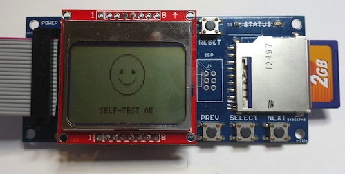
The self-test routine concludes with a happy face if everything is OK, a sad face plus error message if a test fails, and a question mark if something is missing (no SD card, or CPLD is blank). I can’t assume that whoever’s running the test is fluent in English, so icons seemed like the way to go.
The manufacturer’s full firmware programming and testing procedure will be:
- flash the AVR microcontroller
- insert SD card
- update the CPLD firmware from the SD card
- press RESET button and check for the happy face on the LCD display
I’ve timed this repeatedly, and it takes about 1 minute 20 seconds, including the time needed to plug and unplug all the cables, cards, and the LCD. Directly or indirectly, this procedure will test everything except the CPLD-to-Macintosh interface (10 pins), the SELECT button, and the SD card write-protect signal. It’s not a perfect test because the CPLD-to-Mac pins aren’t covered, and occasionally my Mac-based testing uncovers intermittent I/O errors that wouldn’t be detected by this kind of testing anyway. But it should catch the majority of typical assembly errors, while also saving me the time needed for firmware programming, all at a reasonable cost. Check back in about four weeks to see how it turned out!
Read 8 comments and join the conversation
8 Comments so far
Leave a reply. For customer support issues, please use the Customer Support link instead of writing comments.
now you are ready to go big time 🙂
This is great information for people looking to have something manufactured on a larger scale.
I can provide some information regarding pre-programmed chips. Most manufacturers and many distributors offer this service. If you look at the Digikey product page for, say, a Digireel TQFP ATmega328, there’s a line below the product description that gives some information for pre-programming. http://www.digikey.com/product-detail/en/ATMEGA328-AUR/ATMEGA328-AURDKR-ND/3441266
Every time I’ve done this, the procedure has been largely the same. You send the manufacturer/distributor a binary and any fuse or other device specific settings. They then send you a First Article for inspection. Once that’s done and you’re satisfied, you are issued a part number that you can use to order the programmed chip(s). It’s usually no more complicated than that.
How much more did it cost to order a pre-programmed part from Digi-Key, as opposed to the same blank part? Like everything else, I assume it depends on how many you order.
Great article and well written. I notice that you use a premade Nokia 5110 lcd module. I’m curious if you sourced these yourself (only $3 each delivered on ebay!) or if the manufacturer obtained them?
Nevermind, just found your previous article specifically about the lcd!!
Steve: Thanks for sharing your experiences, very informative. You mentioned that the self-test doesn’t test the CPLD-to-Mac I/O. I wonder if you’d get some mileage out of creating a loopback connector, so that you could actually test some or all of that interface?
Yeah, that would be the logical next step, and I’m already having them attach a custom connector to that port for power. There are several things that would make this challenging, though:
1. All but one of those pins is an input to the CPLD. Testing 9 chip inputs with 1 output isn’t possible. So I’d have to also connect some other outputs somewhere, or use a different CPLD configuration just for testing purposes, or maybe try to do the whole thing using JTAG TEST mode.
2. The other connections are all tested by the AVR micro controller. But these 10 aren’t exposed to the AVR, so there’s no way for it to setup the test or know if it passed or failed. I’d need a different CPLD configuration that takes test commands from the AVR and reports results back, or JTAG TEST again.
Making a special test-only CPLD config isn’t attractive, because then the vendor would have to spend extra time flashing the real production config after testing was finished, increasing the cost. There’s not enough space left in the production CPLD config to add extra testing features. So I guess JTAG TEST would be the way to go, and it’s theoretically possible if I read lots of data sheets, but looks intimidating.
Also, any test involving a loopback connector would fail when connected to a real Mac without the loopback wiring, so I couldn’t always run the self-test at power-on as I do now. And any test that involved changing the I/O direction of those 10 Mac interface pins wouldn’t even be safe when connected to a real Mac. Hmmm…
How about instead of a plain connector you have a board they plug into which sequence through the emu’s inputs?