

Archive for April, 2015
5.25 Inch Disk Kickoff
I’ve started working on Apple II 5.25 inch disk emulation for Floppy Emu. It’s still early, and it’s progressing more slowly than I expected, but I think it’ll work. It will be great to have a new mode to emulate the zillions of 5.25 inch Apple II disks out there. I’ve been using the IIgs for my testing, but it should work on any Apple II series machine. No adapters needed either – just plug in the Emu board and go.
The first step was to convince the computer that there was even a 5.25 inch drive connected. That took more effort than I expected, because the 5.25 drive doesn’t have any way of directly telling the computer “I’m here”. After some trial and error, I discovered that the computer just blindly turns on the drive motor and starts reading from it. If it gets valid data or garbage data, either way it knows there’s a drive attached, but if it gets no data at all then it assumes no drive is present. I had assumed an empty drive would send no data, but some investigations with a logic analyzer proved that theory wrong. To make Floppy Emu be detected as an installed drive, I had to change the firmware to send a constant stream of sync bytes even when there’s no disk inserted.
Stepping the drive head to the correct track proved to be a major hassle. The Apple II directly controls a 4-phase stepper motor in the 5.25 disk drive, activating each coil in the correct sequence to move the stepper in or out. I modified the firmware to monitor these control signals, and simulate what would happen to a real stepper motor. This was more difficult than it might sound, because the control signals can be driven in various ways to produce half steps, full steps, or weird combinations of inputs that don’t do anything well-defined. Fortunately I think I’ve got it working now.
Speaking of the stepper controls, I hooked up my logic analyzer to the disk interface signals so I could see what was going on. For all the years I’ve been working on floppy emulation, I can’t believe I’ve never done this before! I normally rely on indirect methods of observation, from the computer or the Emu, and haven’t had a direct window onto the actual disk signals.
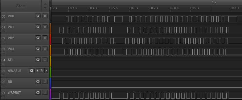
The waveform above shows the characteristic chukka-chukka-chukka of an Apple II 5.25 inch drive when the computer recalibrates the track position. During the first section, the phase lines are repeatedly activated one at a time in order, from lowest to highest, which moves the drive head outwards. Then there’s a pause, followed by a second section where the phase lines are activated from highest to lowest, which moves the drive head inward. Eventually the head hits a mechanical stop at track 0, making the familiar rattling sound of a 5.25 inch floppy drive.
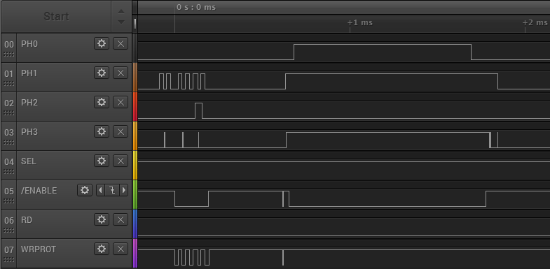
For comparison, the waveform below shows what happens on the IIgs, just a brief moment after the power is turned on. Note that the time scale is much smaller, and the phase lines aren’t driven in sequence, but instead each one has an independent behavior. I believe this is the IIgs asking “Hello, are you a SmartPort hard disk? No? OK then.” I’ll find out more when I look further into SmartPort HD emulation.
Copy II Plus, an Apple II disk copy program, has some very nice sector and track diagnostic tools built in. Using these I was able to verify that my track stepping logic is working. I was also able to capture a raw dump of an entire track, showing all the bytes straight off the disk (or the Emu), without any kind of post-processing to try to identify where the sectors are. This will be incredibly valuable as I start to work on actually sending the correct disk data.
In the image below, you can see that it’s already sort of working. This shows a Copy II Plus dump of track 0 of an emulated 5.25 inch disk from Floppy Emu. The data itself is actually from a Macintosh disk, with Macintosh style sector headers, so that part obviously isn’t right. But what’s encouraging is that the raw data is being received correctly by the Apple II – I circled the familiar D5 AA 96 that marks the start of a sector, and D5 AA AD that marks the start of the sector’s data payload.
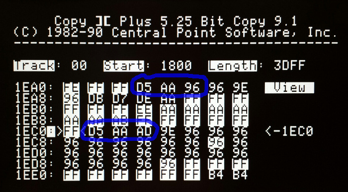
Unfortunately, some of the data is received incorrectly. The screenshot shows an example that mostly worked, but in many cases, parts of the sector are garbled. The data payload shown above should have contained hundreds of “96” bytes after the D5 AA AD, but it only has 23 of them before something goes wrong. Even the highlighted “FF” sync bytes before the data payload are wrong: some of them show “AA” and other incorrect values. Maybe the bit rate is slightly off? Bad voltage levels? Microcontroller interrupts messing with the bit timing? I’ll figure it out eventually.
Read 3 comments and join the conversationROM 03 Revisited
Good news, Apple II fans! The Apple IIgs ROM 03 mystery has been solved. A few weeks ago I added new support to Floppy Emu, for emulation of 3.5 inch Apple II disks. I used it to boot my Apple IIgs with GS/OS… fun. Then I started hearing from other IIgs owners for whom the new firmware didn’t work, but I couldn’t understand why… not fun. The issue seemed related to differences between IIgs version ROM 01 and ROM 03, but I wasn’t sure what was going on or how to fix it. This prompted the post Apple IIgs ROM 03 Headaches. Now, after a lot of head scratching, I think I’ve finally got it figured out.
A huge “thank you” goes to Steve Palm, who did an extraordinary amount of testing under different conditions with his ROM 03 machine, and to Jason Galarneau, who loaned me a ROM 03 machine to experiment with directly. What I learned was that the ROM 03 problem is caused by incomplete decoding of the disk drive enable signals, causing the Emu to respond at inappropriate times. I had actually diagnosed the problem correctly in this earlier post, and I even provided a potential solution there, but I somehow convinced myself this wasn’t the ROM 03 problem, or wasn’t the main problem. Wrong!
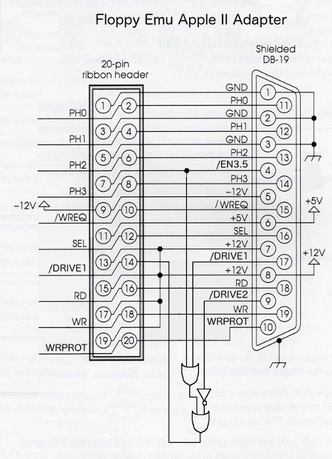
On a Macintosh floppy port, there’s a single active low signal called /ENABLE that tells the drive when to wake up. The earliest Apple II 5.25 inch drives worked the same way. But Apple later complicated things in order to support daisy chained disk drives, and chains containing multiple different types of drives, to where on an Apple IIgs the floppy port has three different enable signals: /DRIVE1, /DRIVE2, and /EN3.5. Floppy Emu was only listening to /DRIVE1, and wasn’t even connected to the other signals. The difficulties are described in much more detail in the earlier post, so I won’t repeat them here.
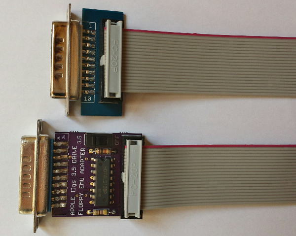
The final step was to build a prototype of the external adapter described in the earlier post. Since the Emu board lacks connections for /DRIVE2 and /EN3.5, the external adapter is responsible for decoding those signals along with /DRIVE1, and passing the result to Floppy Emu as a single /ENABLE signal. And what do you know, it works! No more ROM 03 problems, and no more limitations on where the Emu can appear in the disk daisy chain.
The adapter prototype also includes a couple of resistors not shown in the diagram. There’s a 10K pull-up resistor for /DRIVE2, because that signal isn’t connected on a Mac or Lisa. And there’s a 470 ohm series resistor on WRPROT, which is the only signal that changes direction between the Mac/Lisa and Apple II firmwares. No more worries about possibly damaging something if you accidentally use the Apple II firmware while connected to a Mac.
A Universal Apple Adapter for Floppy Emu
The original name I gave the adapter is misleading – it’s not an adapter for the Apple II, it’s an adapter for everything including the Apple II! There’s a photo of the adapter prototype at the top of this post, with the current do-nothing adapter also pictured for comparison. The new universal adapter has a switch on it. Set it to “3.5” if you want to emulate an Apple Disk 3.5 for Apple II, or set it to “OFF” if you want to emulate any other type of Apple II, Mac, or Lisa disk.
There’s potential for confusion with this new universal adapter, so I’m trying to choose names and terminology carefully. The adapter is only REQUIRED in a few specific circumstances, but it’s COMPATIBLE with all circumstances, so you can just plug it in and leave it there. Macintosh computers and the Lisa don’t need the adapter, and you can also boot an Apple IIgs ROM 01 machine from the Emu without the adapter. And when Apple II 5.25 inch and SmartPort disk emulation is ready, those shouldn’t need the adapter either. But for 3.5 inch emulation on a IIgs ROM 03 machine, or 3.5 inch emulation on a IIgs ROM 01 machine where the Emu is not the boot disk, this adapter is just what the doctor ordered.
So what’s next? I hope to have some of these adapters available for sale shortly. They’ll be offered as an alternative to the existing “convertible extension cable”, for a few dollars more. People who expect to use Apple II 3.5 inch disk emulation (mainly IIgs owners) along with other emulation modes can use the new cable, while people who don’t care about Apple II 3.5 inch disk emulation can stick with the current cable. Longer term, I hope to build the functionality of the universal adapter into a new Floppy Emu, but that won’t be any time soon.
Crazy idea: with other external adapter boards like this one, with a different external connector, it might be possible to develop Floppy Emu disk emulation firmware for completely different computer platforms. Atari disk emulation, anybody? Amiga? They all operate on the same basic principles as the existing Floppy Emu disk emulation. Yes, there are many differences in the details, but the more emulation modes I implement the better I’m getting at abstracting the drive-specific parts from the shared functionality. Maybe someday…
Read 8 comments and join the conversationCircuit Protection: Economics and Electronics
Remember this problem that I analyzed a year ago, with mysterious damage to the CPLD chip? I still haven’t found a permanent solution. It’s rare enough that it’s not much trouble to just repair or replace affected boards, but it’s annoying, and I’d sure like to fix it if I can. I’m not completely certain what causes it, nor how to fix it, but I have a theory I’m going with. The challenge is that the extra cost of parts and assembly to address the problem may actually be more than the cost of making occasional repairs, creating the awkward result that I would lose money by making things more robust.
This type of BMOW post often gets picked up by Hack-a-Day or Hacker News, spawning an off-site discussion thread about how stupid I am. Please be kind and understand that I’m not a professional, and if you think I’m doing it all wrong, I probably am! Leave your feedback in the comments below, and let me know how I could have done it better.
Economics
This is a low-volume hobby product, a disk drive emulator, and it’s designed and built by a single person in his spare time – me. In the past year, I estimate I’ve spent about $500 on hardware repairs and replacements for boards that had CPLD damage. That includes direct costs, as well as the cost of my time. $500 may sound like a lot, but I’ve sold about 300 boards during that time, so the amortized cost is only $1.67 per board. There’s also an intangible cost when a product fails and a customer has to return it – they get annoyed, my reputation suffers, and maybe I lose out on some future sales. That’s not good either. Including those intangibles, let’s say the total cost of this issue is an even $2.00 per board.
Assuming I knew exactly what the problem was and exactly what to change in order to fix it, implementing the change would need to cost less than $2.00 per board. Otherwise I would be spending more to prevent the problem than the damage it caused! It would be like buying Monopoly’s “Get out of Jail Free” card for $60, when getting out of jail normally only costs $50. And what if I wasn’t certain the proposed change would fix the problem? Then the cost of the change would have to be even less than $2.00, in order to compensate for this uncertainty. Maybe $1.50 or less, depending on how confident I was in the solution.
The reality is that implementing a change for less than $1.50 or $2.00 may not be easy. I suspect the problem is related to over-voltage on the 12 CPLD I/Os, and if I use a resistor or buffer on each input, it will require a minimum of 24 extra pins/pads on the board. The board assembly cost is around $0.05 per pin, so that’s already $1.20 right there, without even considering the cost of the parts themselves or any other extras. Add in the cost of the new parts, and adjust for any uncertainty in the solution, and the total costs might outweight the benefits. D’oh!
Electronics
If you haven’t already, check out last year’s post, especially the many excellent comments from readers. Based on that discussion, and my observations since then, I think last year’s over-voltage input theory is probably correct.
In the normal setup, the CPLD chip on the board is connected via a 3 foot cable to a vintage Macintosh. The Mac has 5V outputs. The CPLD has a 3.3V supply, with 5V tolerant inputs. In normal usage everything is fine, but I suspect there are occasional transients that cause a problem. From the CPLD datasheet: “The 3.3V VCCINT power supply must be at least 1.5V before 5V signals are applied to the I/Os.” In other words, the 5V tolerance of the CPLD’s inputs disappears if the CPLD’s supply voltage is under 1.5V. Could this be happening? What problem would that cause?
The board is powered indirectly from the Mac’s 5V supply, delivered by that 3 foot cable. When it’s first powered on, a 3.3V regulator on the board begins to work, and eventually it will raise the CPLD’s supply voltage to 3.3V. But what happens if the Mac applies 5V I/O signals before the CPLD’s supply voltage has risen above the critical 1.5V threshold mentioned in the datasheet? This might happen at initial power on, if the 3.3V supply is slow to ramp up. It would be even more likely to happen if the board were “hot plugged” while the Mac was already turned on. Or a similar issue might occur long after power-up, if something caused the 3.3V supply to droop back down below 1.5V while 5V I/Os were applied. This might happen during power-down, or because an SD card was hot-swapped in the board, causing a large inrush current to briefly overwhelm the 3.3V supply. In any of these examples, 5V would be applied to the CPLD inputs during a time when they were not 5V tolerant.
What problems might this over-voltage cause? The most likely result is damage to the ESD protection diodes. Most modern chips have some kind of protection circuitry at each pin, to guard against static electricity or a brief voltage overshoot. The exact design of this protection circuitry normally isn’t specified, but the typical example looks like this:
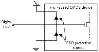
image from raspberrypi.org
In a typical chip, both protection diodes probably have a standard 0.6V drop. If the input goes below -0.6V, the bottom diode will begin to conduct, clamping the input voltage and preventing it from going any lower. If the input goes above VCC + 0.6V, then the top diode will begin to conduct, similarly preventing the input voltage from going any higher. When either diode conducts, a large amount of current may flow through the diode, depending on the resistance of the digital input line, and the output impedance of whatever’s driving it. I’ve failed to find any specifics on the CPLD’s diodes, but it seems they’re normally designed to tolerate very high voltages and currents, but only for a very brief time – like a few nanoseconds. Try to pass even a modest DC current through the diodes, like a few milliamps, and they may burn out.
In the case of this CPLD with its 5V tolerant inputs, I’m guessing the top diode actually has a drop of 2.2V instead of 0.6V (or it’s a few diodes in series with a 2.2V total drop). So under normal operation with a 3.3V supply for VCC, that diode wouldn’t begin to conduct until the input voltage exceeds the CPLD’s maximum rating of 5.5V. But despite the difference in voltage drop, the theory should be the same as with a standard ESD diode.
What’s going to happen if VCC is actually much lower than 3.3V, or zero? Then the diode will begin to conduct when the input voltage exceeds 2.2V, and it will keep conducting as long as this condition persists, or until it burns out. So how much current can the diodes tolerate, and for how long? I don’t know, and haven’t been able to find any straight answers, but I’ve seen estimates between 0.1 mA and 50 mA for max ESD diode current, with potential damage from transients that exceed that level for as short as a few milliseconds or even microseconds.
I don’t have any hard data to prove this theory, but it’s consistent with the observations I’ve made and with behavior reported by other people using the same CPLD in other applications. So until a better theory comes along, I’ll assume the problem is blown ESD protection diodes.
Possible Solutions
There are 12 I/O lines between the Mac and the CPLD. 10 of these are CPLD inputs: 5V signals from the Mac connected to the CPLD’s 5V tolerant inputs. One is a CPLD output: a 3.3V signal that’s still high enough to exceed the Mac’s 5V Vih threshold for a logical “1” value. The last can be an input or an output, depending on which kind of disk drive is being emulated. So I need a solution that ameliorates or prevents an over-voltage situation on 11 input pins, while also enabling one of those pins to be used as an output sometimes.
Inline Resistors – The simplest and cheapest solution is to add inline resistors in the signal paths of all 12 signals. Under normal operation, the inputs draw negligible current, so there will be negligible voltage drop across those resistors and the function of the circuit will be unaffected. But in an over-voltage situation where the CPLD’s VCC supply is too low and the ESD diode begins to conduct, the resistor will limit the current to a level that’s safe for the diode.
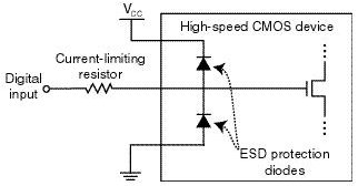
image from raspberrypi.org
The tricky bit is choosing what resistor value to use. There’s some parasitic capacitance on the cable, the board trace, and the CPLD input itself, and this capacitance combined with an inline resistor forms a classic RC circuit. The input voltage will no longer be able to change as rapidly before, rounding the corners of signal edges, and reducing the maximum signal switching rate that’s possible. So too high of a value for the resistor is bad. Fortunately the disk drive signals are comparatively slow, in the 1 or 2 MHz range at most. I estimate I could use a resistor as large as maybe 3.3K ohms before this RC filtering affect would cause problems, but I may be way off.
But wait! The resistor also needs to protect the ESD diode by limiting the current, and too low a value for the resistor will be ineffective. The minimum resistor size depends on the characteristics of the ESD diode, which are unknown. Let’s assume it has a 2.2V drop, and can tolerate 1 mA max. With a 5V input and the diode terminated to ground, that would leave 2.8V across the resistor, so a 2.8K ohm or larger resistor would be needed in order to limit the current to 1 mA.
Would this solution work? Probably, and it would only cost about $0.12 on top of the ~$1.20 assembly cost. But the overlap of resistor values is uncomfortably narrow between “too high for the circuit to work” and “too low to offer any protection”. And the values themselves are based partly on guesswork rather than any hard numbers from a datasheet. Some people feel that relying on the ESD diodes in any way is bad form, and the absence of real specs for the diodes is one reason why. Anyone with experience who might suggest an appropriate resistor value here that would satisfy both requirements – I’d love to hear from you.
Resistors with External Diodes – What about implementing my own over-voltage solution, external from the CPLD, with an inline resistor and a diode up to 3.3V for each signal? This would essentially do the same thing as the ESD diode, but with a beefier diode capable of handling more current, and for which I would know the actual specs. With a beefier diode, I could also get away with a smaller inline resistor, so the RC filtering effects would be reduced.
Standard silicon diodes with a 0.6V drop probably wouldn’t work. When the CPLD’s power supply is below the magic 1.5V threshold, its inputs aren’t 5V tolerant, but it’s not specified exactly what voltage is safe in this situation. If we assume 3.6V is the highest safe voltage, then the diode would need a voltage drop less than 0.3V.
The biggest problem with this approach is the number of parts required, and resulting cost. With a separate resistor and diode on all 12 signal lines, that would be 4 new pins/pads per signal line, or 48 new pins total. The assembly cost alone would be almost $2.00, without even considering the cost of diodes, pushing this solution to the point where it would cost more to implement than it would save. Maybe there’s some kind of single-chip ESD circuit solution I could use, that has a bunch of appropriate resistors and clamp diodes built into it? That might help bring the pin count down to a more manageable level.
Voltage Dividers – Another approach is to use a pair of resistors in series for each signal line to form a voltage divider. Something like this:
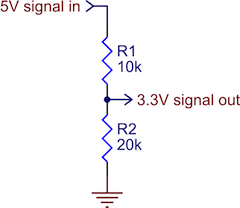
image from pololu.com
As long as the resistor values were in the proper ratio, and the 3.3V input itself drew minimal current, this would work OK as a level converter. It would prevent 5V signals from ever reaching the CPLD. The downside of a voltage divider is that when the 5V input is high, there’s current constantly flowing to ground. The IWM chip in the Mac is only able to source a paltry 0.32 mA for a high-level output, and to limit the current to that level, the combined resistance of the two resistors would have to be at least 15.6K ohms. That’s an awfully large resistance, and would probably create the types of unwanted RC filtering effects I feared would interfere with normal circuit operation. Using voltage dividers would also double the total number of components required for circuit protection, relative to inline resistors.
Level Shifter – The last solution I’m considering is a few level shifter chips. Any kind of chip would do, as long as it had non-inverting buffer outputs at 3.3V, with fully 5V-tolerant inputs. Candidates are the 74LVC244, or the 4050B. This would prevent any signal voltage above 3.3V from ever reaching the CPLD. With one input and one output pin per I/O signal, the number of pins and the assembly cost should be about the same as with passive resistors. A quick look at the 4050B shows I could buy a pair of them, enough to buffer 12 signals, for about $0.35 in quantity. That might work.
The problem with using level shifters is that they’re unidirectional. What about that one signal that’s either an input or an output, depending on the type of disk drive being emulated? This solution wouldn’t work for that, so I would need some additional bidirectional protection circuitry just for that one signal. I’m not sure what that might be or how complex it would become.
The other drawback of using level shifting chips is that they’re comparatively big, and it might be difficult to find space for them on the board without relocating everything and re-routing the whole thing from scratch. Resistors and diodes, even in multi-element packages, tend to be smaller and easier to squeeze into tight spaces.
Suggestions?
Have I analyzed the economics or the electronics wrong? Any other good solutions that I overlooked? Please leave your suggestions in the comments.
Read 19 comments and join the conversationChanging the Macintosh Start-Up Sound
Beep! Wouldn’t it be fun to customize the cheery little square wave greeting of your Mac 512K or Plus? With a Macintosh ROM-inator kit installed, now you can. This isn’t a control panel like SoundMaster, that plays while the OS is loaded from disk – it’s the sound that you hear the moment you flip on the power switch. On a normal vintage Macintosh, this sound is generated on the fly by code in ROM, but with ROM-inator you can alter this behavior and create any kind of sound you’d like. Let’s get started!
This tutorial assumes you already have a ROM-inator kit installed in your Mac 512K, 512Ke, or Plus. If not, follow the link to learn more or buy a kit. The ROM-inator is capable of many customizations beyond just startup sound hacks, including making a bootable disk contained entirely in ROM.
The steps below may look long and complex, but that’s because I want to be thorough and avoid skipping any details. In a nutshell, all that’s necessary is to convert a sound to the proper format, optionally patch a byte in ROM to reflect the sound’s duration, and then use Flash Tool to store the new sound in ROM.
Making the Start-Up Sound
First, you’ll need a sound sample to replace the default beep. This can be something you recorded yourself, or a sound downloaded from a source like Freesound.org. The ideal sound will be 0.66 seconds in duration, matching the length of the standard beep sound, but durations from 0 to 1.3 seconds are possible if you’re willing to do a small amount of extra hacking as explained below. For this exercise, I’m going to use the MOOF! sound of Clarus, the DogCow, which I found here. The DogCow was the mascot of Apple Developer Technical Support for many years during the vintage Macintosh era.
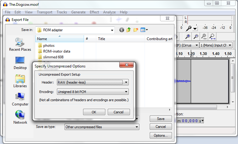
Next, you’ll need to convert your sound to mono 22 kHz 8-bit unsigned raw format. The free audio tool Audacity can do this, converting from other formats like WAV or MP3 if necessary. The “moof” sound is a WAV file, so let’s open it with Audacity and take a look:
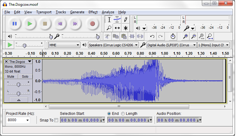
The moof sound is just under 1.5 seconds in duration – longer than the 1.3 second limit. Fortunately everything from about 1.2 seconds onward is just silence, and can be deleted. In the Audacity window, click the mouse in the timeline at 1.2 seconds, then drag it to the right to select the range from 1.2 seconds onward. Then hit the delete key on your keyboard, and everything from the 1.2 second mark to the end will be removed. In my case, I ended up with a sound that Audacity said was 1.203 seconds in duration.
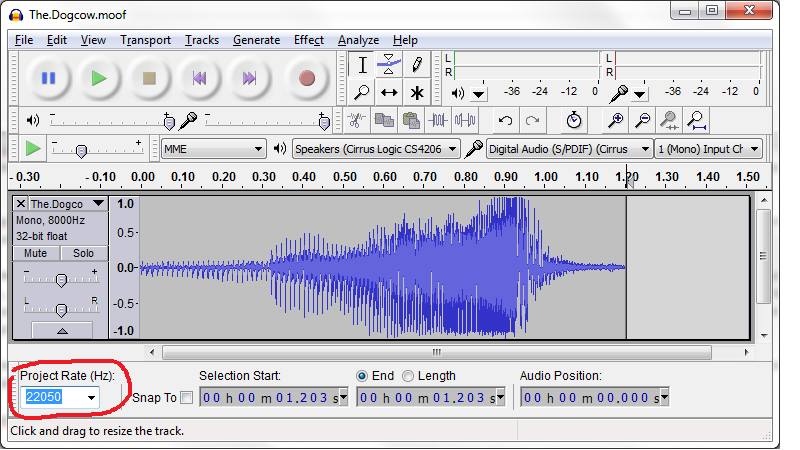
The screenshot shows that the moof sound is mono 8 kHz 32-bit float format, so it needs to be converted. First, change the “project rate” selection in the lower-left corner to 22050. Then go to the File menu, and select “Export…”. In the dialog box that appears, press the Options button, and select RAW (header-less), Unsigned 8 bit PCM. The “Save As Type” should be set to “other uncompressed files”. Then save the converted file. If a box appears asking for metadata, ignore it and save. See screenshots:
Adjusting for Sound Duration
If your sound is 0.66 seconds long, then you’re done – you can move on to the next step below, storing your new sound in ROM. But if the sound is longer or shorter than 0.66 seconds, you’ll need to make a one-byte change to the Mac ROM startup sound routine. If you don’t make this change, your sound will either be cut off too early, or will keep playing past its end while interpreting random memory as sound data. It won’t hurt anything, but it won’t be very pleasant for your ears.
Download the file code-patched.bin, which contains the default ROM code for ROM-inator. (By the time you read this, the version linked here may be out of date – see the ROM-inator main page for the latest version.) You’ll need a binary editing tool such as xvi32 to make a one-byte change to this file. Open the file, and examine the byte at offset 0xEF hex, which is offset 239 in decimal. The value at that offset should be 0x28 hex, or 40 decimal. This is the duration of the startup sound, in sixtieths of a second.
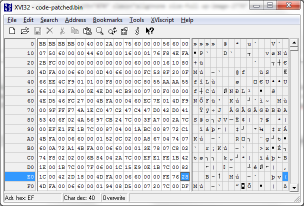
Multiply the duration of your sound by 60, truncate the result to a whole number, and write it at offset 0xEF, replacing the 0x28 value that was there previously. My sound is 1.203 seconds, times 60 is 72.18, so I’ll write the value 72 decimal, which is 0x48 hex. Then save the modified file as code-patched-for-sound.bin.
Storing the New Sound
The last step is to copy the files you created onto your vintage Mac. You’ll need to copy the new sound file, the duration-adjusted ROM code (if any), and the utility program Flash Tool (found on the ROM-inator page). My preferred way to copy the files from a modern PC to a Mac Plus is with Floppy Emu, but it can also be done via a Localtalk network, or by using another Macintosh as a bridge machine for copying to an 800K floppy disk. With Floppy Emu, I put a blank 800K disk image file on my SD card, use a tool like HFVExplorer (Windows) or Fuse HFS (Mac OS X) to copy the files into the blank disk image, then put the SD card in the Floppy Emu and connect it to the vintage Mac.
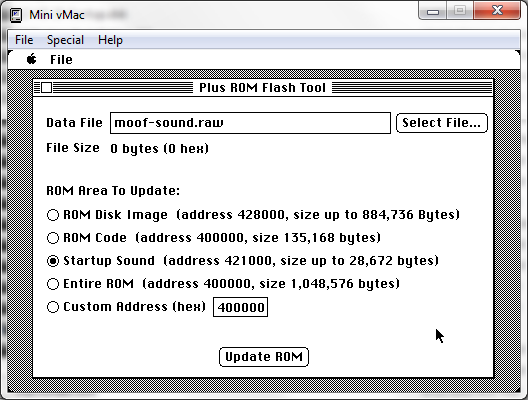
Run Flash Tool on the Mac, and click the radio button to indicate you want to update ROM with a new startup sound. Select the sound file you made, and hit the “Update ROM” button to perform the update. The process only takes a few seconds. If your sound’s duration was not 0.66 seconds and you made a duration-adjusted ROM code file, you’ll need to store that in ROM too. Click the radio button to indicate you’re performing a ROM code update, select your code-patched-for-sound.bin file, and apply the update.
Happy sound hacking!
Read 1 comment and join the conversationApple IIgs ROM 03 Headaches
I’m still chasing an explanation for why some Apple IIgs computers won’t play nicely with Floppy Emu’s new 800K 3.5 inch Apple II disk emulation. I described the symptoms in my previous post – ProDOS and GS/OS disk images boot straight up on my IIgs without problems, and on most other IIgs systems, but for a couple of people it just hangs forever in the READ state on track 0. Both people who reported this have the relatively rare ROM 03 version of the IIgs, so I’m assuming it’s a compatibility problem between ROM 03 and the more common ROM 01. But what’s the problem exactly? And how can I fix it?
The biggest obstacle at the moment is lack of information. I don’t have a ROM 03 machine, and I can’t find one anywhere, so I can’t troubleshoot this myself. I’ve exchanged emails with two ROM 03 owners who are willing to help, but so far I’ve only gotten detailed information from one, and one data point isn’t enough to draw any conclusions. What seems like a compatibility problem might just be a hardware issue with one specific computer or Emu board.
Despite working mostly in the dark while trying to solve this, I have some theories about what might be going wrong.
Crazy WRPROT Circuits
There are documented incompatibilties between ROM 03 and some real Apple 5.25 inch floppy drives, although the details are fuzzy and sometimes seem contradictory. According to this section of the Apple 2 wiki, ROM 03 is not compatible with the Apple UniDisk 5.25 or DuoDisk. The explanation seems muddy, with two paragraphs that appear to offer two unrelated explanations, but one of them is related to the circuitry behind the drive’s WRPROT (write protect) signal. This is the signal that indicates whether the disk in the drive has the write-protect notch covered – remember those? According to the wiki, “incompatible drives on these models will just spin at startup.” Sounds a lot like what’s happening with Floppy Emu.
There’s also this Apple Tech Info document about ROM 03 and DuoDisk, with a symptom that sounds similar: “The DuoDisk LED for drive #1 will turn on, but the system will not start.” It doesn’t give an explanation, but mentions that booting from a write-protected disk works normally. Again, something about ROM 03 and write protection.
Check out this partial functional diagram of the Disk II 5.25 drive. Notice anything odd about the write protect signal?
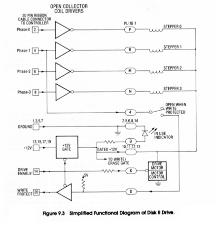
There’s a tri-state buffer for the WRPROT output, controlled by the drive’s ENABLE input. Behind that is a pull-up resistor, and the switch that senses the notch in the disk. But instead of ultimately terminating at GND, the write protect circuit is connected to the drive’s PHASE1 input. When the computer sets PHASE1 to 0, it can then read the WRPROT state as 1 = write protected, 0 = not write protected. But if the computer sets PHASE1 to 1, it effectively disables the whole write protect circuit, and WRPROT will always be 1.
My theory is that ROM 03 has some 5.25 inch drive detection code that sets PHASE1 to 1 in order to disable the circuit, and then waits for WRPROT to go to 1. But if the disk drive has its write protect circuit terminated directly to GND instead of PHASE1, it won’t be disabled, so WRPROT will never go to 1 and the computer will wait forever, unless the disk is actually write protected. My hunch is that the DuoDisk is built this way, which explains why it doesn’t work with the ROM 03 IIgs.
Floppy Emu’s Identity Crisis
Now what does any of this have to do with Floppy Emu’s 800K 3.5 inch Apple II disk emulation? After all, it’s emulating a 3.5 inch disk, where WRPROT behaves completely differently and this issue presumably isn’t relevant. Remember in my last post, when I described how the current design lacks connections for some enable signals used to distinguish between 3.5 inch and 5.25 inch drives? I had sort of dismissed it as not a problem, but my theory is it’s causing Floppy Emu to be identified as a 3.5 inch drive and a 5.25 inch drive. And when it’s identified as a 5.25 inch drive, WRPROT is not going to respond to PHASE1 in the expected way, which may cause a bootup hang on ROM 03 just like with the DuoDisk. My guess is that ROM 01 sees a misbehaving 5.25 drive and ignores it, but ROM 03 sees a misbehaving 5.25 drive and hangs forever, before ever attempting any 3.5 drive access.
The solution is simple, if annoying – use some external circuitry to handle all the enable signals, so Floppy Emu isn’t accidentally detected as a 5.25 inch drive. My last post sketched out a circuit to do this job, and I’m going to build some PCBs to test it. Meanwhile, using the daisy chain board removed from an AppleDisk 3.5 (A9M0106) floppy drive should accomplish the same thing.
SteveP, one of the ROM 03 owners I’ve been corresponding with, tested this theory. He used the A9M0106’s daisy chain board to connect Floppy Emu to his ROM 03 IIgs. And it worked! Sort of. The computer no longer hung at track 0 while attempting to boot. He was able to boot successfully into ProDOS. And he could begin to boot into GS/OS, but then it would fail with errors like “Unable to load START.GS.OS file. Error=$002E” or “UNABLE TO LOAD PRODOS”. So is there another ROM 03 compatibility issue at work here, or does he just have some flakey hardware or some other unrelated problem? With only this one report to go by, I can’t say, but I’ll keep digging.
Read 11 comments and join the conversationMore Fun with Apple IIgs Disks
Last week I wrote about Apple II 800K disk emulation for Floppy Emu, which I used to boot my Apple IIgs. I posted the new Apple II firmware, so anybody with an Emu board and a IIgs could try it for themselves. Now I need help from anyone with the necessary hardware – could you take a few minutes to try it out, and let me know the results? I need as much information as I can get about compatability with different ROM versions and system configurations.
On my IIgs (ROM01 with 512K RAM and no other cards), I can connect the Floppy Emu to the DB19 port, load its Apple II firmware, and it works fine as Apple 3.5 Drive #1. I can boot the IIgs from it, using either ProDOS or GS/OS disk images. I can read and write to the emulated disk, eject it and insert a different disk image, no problems. The only limitation is that the Emu can’t be daisy-chained behind an Apple 3.5 Drive, making it 3.5 drive #2. This is because the extension cable I use, as well as the Emu itself, lacks two enable signals that are important for daisy-chaining.
Yesterday I heard from somebody for whom the Apple II firmware isn’t working correctly, on a ROM03 IIgs. He’s got the Emu board connected directly to the DB19 port on his IIgs, and is using the Floppy Emu Apple II firmware, just like my setup. But he can’t boot from the Emu: a ProDOS floppy image just hangs, and GS/OS floppy images start to boot, but eventually fail with errors like “Unable to load START.GS.OS file. Error=$002E” or “UNABLE TO LOAD PRODOS”. If he boots GS/OS from a hard drive while the Emu is attached, he sees an error about the “AppleDisk3.5 driver” midway through boot-up. They only thing that works is booting ProDOS from the hard drive, then doing CATALOG,S5,D1 to view the contents of the Floppy Emu disk.
Why does this work so poorly for him, when it works well for me? We’ve stepped through troubleshooting ideas by email, including removing the hard drive and other cards, but nothing seems to help. At this point, I think we’ve narrowed it down to either being a hardware problem with this specific Emu board or IIgs, or else a behavior difference between ROM01 and ROM03. That’s why I need as much info as I can get from other Floppy Emu users who’ve tried this firmware on their IIgs.
Apple II Disk Daisy Chaining
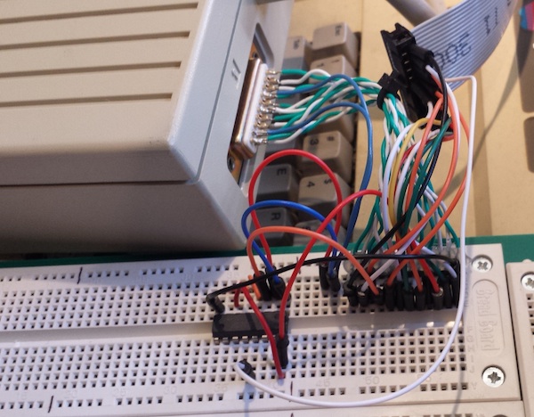
Fortunately there’s some good news among all of this. Remember those two enable signals I mentioned, important for daisy-chaining, but not present on the Emu or Emu cable? Yesterday I put together a hand-made DB19 to IDC20 adapter on a breadboard, along with an external logic chip, and got the Floppy Emu working successfully while daisy-chained as 3.5 drive #2. The adapter is the rather unattractive jumble of wires you see in the photo at the top. While it’s of no immediate value to anybody, the fact that this adapter works seems to confirm that my understanding of all these crazy Apple disk enable signals is correct.
Here follows a long boring discussion of enable signals. Refill your coffee now.
On a Macintosh, pin 17 of the DB19 floppy connector is the drive enable signal. When it’s low the drive is enabled, and when it’s high the drive is not enabled. Only one floppy drive can be connected, so there’s only one enable signal.
On an Apple II, things are more complicated. The Apple 5.25 controller card was the first to use a DB19 connector, and it supported two daisy-chained 5.25 inch drives. Pin 17 is /DRIVE1 enable, and pin 9 (unconnected on the Macintosh) is /DRIVE2 enable. Within each drive, internal circuitry routes the signal from input pin 9 to output pin 17 on the daisy-chain connector. Drive #2 doesn’t actually know that it’s drive #2 – it enables itself by observing /DRIVE1 on pin 17, just like the first drive – only the first drive has sneakily rerouted /DRIVE2 to /DRIVE1. This allows for two drives to be daisy chained.
On an Apple IIgs, it’s even more complicated. Its DB19 connector supports daisy-chaining two 3.5 inch drives, and two 5.25 inch drives – as well as even more SmartPort drives, which I won’t discuss now. Pin 4 (GND on the Macintosh) is /EN3.5, a new signal that enables the 3.5 inch drives when it’s low, or the 5.25 inch drives when it’s high. The 3.5 inch drives must appear before any 5.25 inch drives in the daisy chain. When /EN3.5 is low, the 3.5 inch drives use pins 17 and 9 to enable themselves, and when /EN3.5 is high, the 3.5 inch drives pass through the signals on pins 17 and 9 unmodified to the 5.25 drives behind them.
This is getting complicated, but there’s one final kick in the nuts: when the first 3.5 drive is enabled, by the IIgs setting /EN3.5 and /DRIVE1 both low, you would think the drive would disable the next 3.5 drive behind it by setting both /DRIVE1 and /DRIVE2 high at the daisy-chain connector. But no, the first 3.5 drive disables the second 3.5 drive by setting both /DRIVE1 and /DRIVE2 low! This looks like both are enabled at the same time, which would be a definite no-no, but the Apple 3.5 Drive contains circuitry that recognizes this “double enable” as being equivalent to a disable. Why it’s done this way, I don’t know, but I’m sure it has some purpose.
The end result is that for proper behavior in either first or second position, a Floppy Emu trying to emulate a 3.5 drive should respond only if /EN3.5 and /DRIVE1 are low and /DRIVE2 is high. All three signals must be checked.
Floppy Emu doesn’t have connections for /EN3.5 or /DRIVE2, so it responds whenever /DRIVE1 is low. When connected as a second 3.5 drive, that means it’s unable to recognize the “double enable”, and it responds at the same time as the first 3.5 drive, so neither of them work properly. But when connected as the first 3.5 drive, there’s no double enable to worry about, and /DRIVE2 can be safely ignored. Ignoring /EN3.5 does mean the Emu will also respond to attempts to access 5.25 drive #1, but since there is no such drive anyway, that’s not really a problem.
Building an Adapter
So how can we solve this mess, without requiring a new version of the Floppy Emu? The solution I’ve used is to combine the /EN3.5, /DRIVE1, and /DRIVE2 signals externally, and feed the result to the Emu’s single /ENABLE input. I used a 74LS138 decoder chip to do this, configured to drive a single output low only when the inputs are 0, 0, and 1 respectively. You could accomplish the same thing with a few OR and NOT gates as well. Here’s a schematic:
At some point in the future, I’ll probably manufacture and sell some adapter boards like these. The best way to put the idea into production isn’t obvious, though. This adapter design has 3.5 inch specific functionality baked directly into its circuitry, and it would be wrong if you were using the Floppy Emu to emulate a 5.25 inch or SmartPort disk, or a Mac disk. It would be annoying if people had to attach and remove an adapter every time they wanted to change what type of disk they were emulating. Maybe I could put a switch on the adapter, to select between 3.5 inch and other emulation modes, but that would be annoying too and would add further to the hardware cost. Nobody wants to flip an external switch – they want to select an emulation mode, and just have it work.
Another uncertainty is what form this adapter would take. Should it be an inline adapter, with an IDC20 connector for input and another for output? That would work, but it would mean Apple II users would need a DB19 to IDC20 extension cable, and an adapter – two different things to connect between the computer and the Emu board. A better solution is probably to make a new version of my DB19 to IDC20 extension cable, that has the adapter circuit and switch built into it. But that would drive up the cost by a few dollars – so would I continue to sell the old cable as well, or encourage everyone to buy this new, more capable but more expensive cable? If I sold both cables, would I get tons of email from people confused about which one to buy, or upset because they didn’t understand they needed a specific cable to enable specific types of emulation?
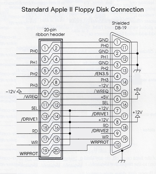
There’s another matter too – for most purposes the DB19 and IDC20 connectors are interchangeable, and there’s a standard pin mapping between the two, shown above. But the /DRIVE2 signal on DB19 pin 9 was only ever used in DB19 cables, and there is no standard mapping for it on the IDC20 connector. So how can I even physcially route that signal on a 20-pin ribbon cable? I could substitute it for one of the existing signals I’m not currently using, like one of the +12V supply lines. That would be fine for Floppy Emu and my adapter boards, but someday someone would surely use one of my cables to do something strange, like connect a Disk II to an Apple IIgs. Then they’d get +12V from the Disk II feeding backwards into the computer’s /DRIVE2 output, causing it to burst into flames and burn down their house.
Sometimes I think about things too much. 🙂
Read 11 comments and join the conversation