

SD Card SPI Initialization
What happens when two devices share the same SPI bus? With a good design, each device is enabled one at a time for use of the bus, and they coexist without problems. With a bad design, SPI communication that’s intended for one device is sent to the other, leading to confusion and buggy behavior. In the Floppy Emu disk emulator, the SPI bus is shared between an SD card and an LCD display. As it turns out, it had a bug like this that escaped notice for almost two years, with the occasionally flaky behavior wrongly attributed to bad SD cards, faulty boards, or the phase of the moon. Doh!
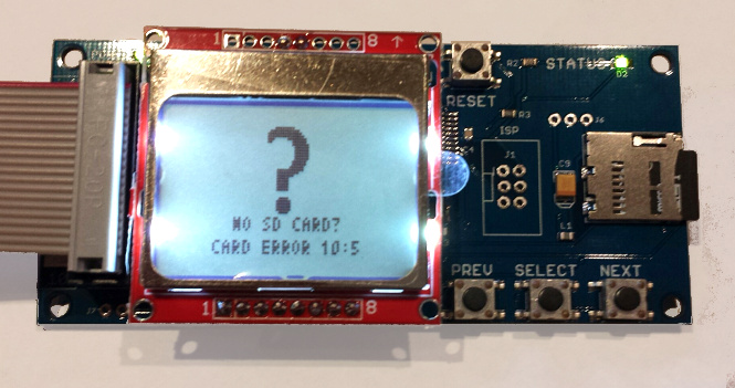
The symptom was a “No SD card” message, with error code 10:5, when using a few specific models of SD card. During startup, the Floppy Emu firmware was sending SPI commands to the LCD to draw an image, then sending SPI commands to the SD card to initialize it. In rare circumstances, the initial communication with the LCD was confusing the SD card, leaving it in a state where it refused to respond to any further commands until the power was turned off and on. This caused the Emu to think no card was present. The problem didn’t always happen 100% of the time, and it appeared to depend on the electrical characteristics of each board and anything attached to it. But for certain models of SD card, it happened so consistently that the only remedy was to use a different SD card.
My solution was simple: initialize the SD card before doing any LCD communication. Grab the new firmware with the fix here:
floppy-emu-1.0R-F13 – Mac Floppy
hd20-0.7E-F14.5 – Mac Floppy + Hard Disk and Lisa Floppy
apple-II-0.1K-F7 – Apple II, for Model B
apple-II-0.1K-F6 – Apple II, for Model A
SPI Mysteries
You might wonder how a problem like this could have gone unnoticed for so long. Looking back over two years of support emails, I only found four problem reports that could be retroactively attributed to this issue. In each case, the person was able to get things working by trying a different SD card, so we chalked up the problem as a damaged or flakey card. It was only recently that I received two reports from people who’d tried multiple cards, all of which failed with the “No SD Card” message and error 10:5. Following up on their hardware, I bought two suspect 16 GB cards (1, 2), and confirmed that they both just plain didn’t work. Ouch. I’ve now verified that the new firmware gets both these SD cards working, and also received confirmation from some other users that the new firmware gets their troublesome cards working too.
So what exactly was the problem? The frustrating answer is that I don’t really know, and my description of the issue intentionally glossed over some important details. It’s true that the LCD communication somehow confused certain SD cards, but I can’t explain why.
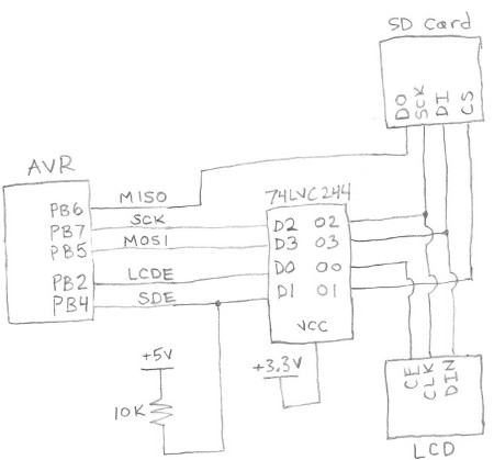
Here’s a simplified diagram of Floppy Emu’s SPI bus. The LCD and SD card are independently enabled by separate, active low signals LCDE and SDE. Because the AVR microcontroller operates at 5V, all its outputs are passed through a 74LVC244 buffer to step them down to 3.3V for the LCD and SD card (the 3.3V signal MISO is an output from the SD card, and doesn’t need level conversion). SDE also has a 10K ohm pull-up resistor to +5V, to ensure that the SD card is disabled when the AVR isn’t actively driving the signal, during reset and microcontroller startup.
The only way it should be possible for the SD card to be confused by LCD communication traffic is if SDE were asserted at the wrong time. Looking at the schematic and the firmware code, I just don’t see how that’s possible. The pull-up resistor ensures that the SD card will be enabled if the AVR isn’t actively driving it. And once the AVR does begin actively driving it, it drives SDE high (unasserted) until it’s ready to begin communication with the SD card. So the card should be disabled during the initial LCD communication, and should ignore whatever is happening on the SPI bus.
If I weren’t so lazy, I would put a scope on the SPI bus, and verify that SDE is truly unasserted during LCD communication. But I’m lazy, and didn’t do that.
A few hints point to an electrical problem. With some cards, the 10:5 error occurred more often when I had an AVR programmer attached to the SPI bus, even if the programmer wasn’t active. And with those same cards, seemingly trivial firmware changes would cause the error to appear and disappear. Sometimes I’d only get the error on half my attempts, so it wasn’t a deterministic problem.
Maybe poor circuit design causes a momentary noise spike on SDE, during startup and LCD communication. Ringing, ground bounce, or cross-coupling of signals might cause SDE to briefly appear asserted when it shouldn’t be, causing the SD card to try to interpret communications meant for the LCD. But if that were the case, I’d expect to see all kinds of similar communication errors with the SD card during normal operation.
Another possibility is that there’s something fishy going on with AVR pin PB4, which is also the SPI SS (slave select) pin. The datasheet mentions that there’s some special behavior related to this pin. But after reading that section of the datasheet, I don’t think that’s the cause.
My last theory is that the problem is caused by accidentally switching the SD card into 4-bit mode. SD cards can operate in three different modes: SPI, 1-bit SDIO, or 4-bit SDIO. The latter two modes use the card’s pins like a conventional data bus. I believe the details of 1-bit and 4-bit SDIO may be proprietary and require an NDA, and every hobbyist-made microcontroller project I’ve seen has used SPI instead.
The catch is that SD cards initially power on into 1-bit SDIO mode, and part of the SD card initialization process is to switch to SPI mode, which will remain active until power off. With the old firmware, during the Floppy Emu’s initial LCD communication, the SD card was still in 1-bit SDIO mode rather than SPI mode. I don’t know anything about 1-bit SDIO mode, but maybe the chip select input is used differently in that mode, and my LCD communication was accidentally triggering a switch to 4-bit SDIO mode. As I understand it, once switched to another mode, that mode will remain active until power off, which is consistent with the “zombie SD card” behavior I observed with certain cards under the old firmware. Hmmm…
Read 3 comments and join the conversation3 Comments so far
Leave a reply. For customer support issues, please use the Customer Support link instead of writing comments.
A couple of points:
1) SDIO interfaces are more available now. I purchased a STM32F4
Discovery board a while back just so I could play with its SDIO
interface. It works well and is very fast. No NDA required. There are
also surprisingly cheap stand alone SDIO interface chips available.
2) You switch the SD card to SPI mode by sending CMD0 with the CS pin
pulled low. But when you were talking to the LCD you were clocking data
with CS high. Just as if you were trying to run it in SDIO mode and the
card will be trying to interpret that data as SD mode commands. The SD
specification says that the first reset command (CMD0) after power up
determines the mode and it cannot be changed other than by cycling
power. So initializing the SD card into SPI mode before doing anything
else on a shared SPI bus is required. Why some cards have trouble and
others do not is a mystery but I have found cards that are not compliant
with the specification in odd ways.
Unfortunately the SD specifications documents available to the general
public have had a lot of useful information removed. Things like the
signal lines. But I have been interested in this for a while so I have
squirrelled away a copy of an old Sandisk document on MMC cards
(manual-rs-mmcv1.0.pdf, which Google tells me can still be found) that
doesn’t have that information removed. Dated but occasionally useful.
Thanks! So if I understand your point #2, when the card first powers on and before it’s switched to SPI mode, it will potentially respond to activity on the SCK and DI inputs even when its /CS input is not asserted (pulled low)? That would certainly explain the behavior I saw.
Absolutely. It is looking for CMD0 and the only thing that differentiates SD from SPI mode is the state of the CS signal line while that command is transmitted. While in SPI mode the card will tend to synchronize its byte boundaries to the CS transition, the first bit of a command packet is always zero and is the start bit. So it doesn’t need that CS transition to synchronize on.
I would expect that a card would not put itself into SD or SPI mode until it received a valid CMD0 packet. But it wouldn’t surprise me to find a card that would switch to SD mode after seeing an invalid command packet with CS high.