

Capacitor Replacement in a Vintage Power Supply
Capacitors don’t last forever – an unfortunate fact of life for those who collect vintage electronics. The common electrolytic capacitor is one of the most problematic. It’s the type that looks like a little metal can, and after a couple of decades electrolytics tend to start leaking corrosive capacitor goo onto the PCB. You may recognize the strange smell of fish as an early warning sign. Eventually the goo will destroy traces on the PCB, or the changing electrical properties of the capacitor will cause the circuit to stop working. If you want to preserve your vintage equipment, that’s when it’s time for a “recap”.
I have an old Macintosh IIsi computer that dates from around 1991. A few years ago it started acting funny and having trouble turning on, so I sent the logic board to Charles Phillips’ MacCaps Repair Service. He did a great job with the capacitor replacement, and the machine was working great again. But then a few months ago it started to develop new problems that pointed to the need for a power supply recap. I could rarely get it to turn on at all, and when it did, I couldn’t get it to turn off again without unplugging it. Simply plugging the computer into wall power without turning it on caused strange clicking noises from the PSU. And oh, that fish smell.
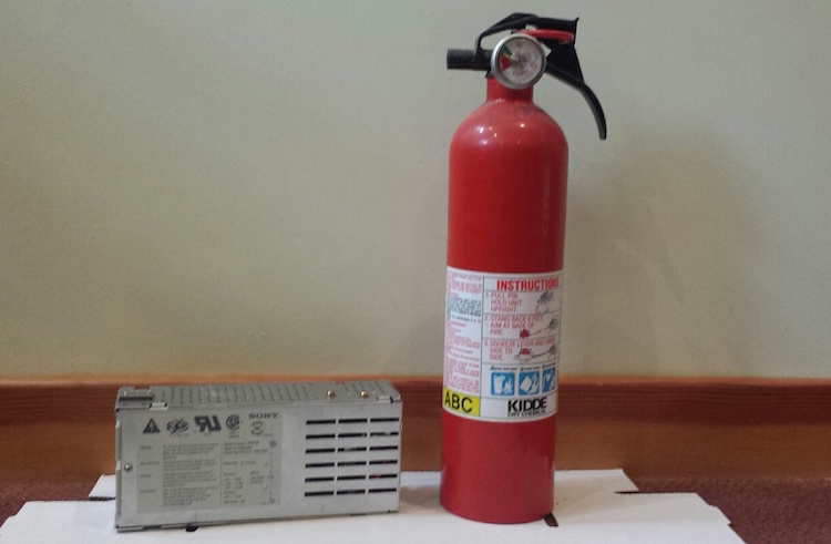
I was going to send the PSU off for a recap. After all, there’s a big warning printed right on the metal cover saying danger, do not open, no user-serviceable parts inside. And while there’s not much danger in a 5 volt logic board, there is a potential for real danger in a power supply drawing 5 amps at 110 volts AC. But then I thought no, I should really get comfortable doing this kind of work myself. I have the tools and the skills, just not the experience or confidence. What’s the worst that could happen? OK, it could blow up and catch fire, but I’ve got a fire extinguisher. 🙂
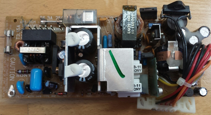
There are 12 electrolytic capacitors in this power supply, whose types and values are listed here. Two of these are surface mount caps on a daughterboard that’s connected to the main PCB, and the others are all through-hole caps. Because I’m both timid and lazy, I really did not want to replace 12 caps. After reading this discussion thread from someone who did a similar repair, I decided to replace only the three capacitors that seemed most likely to be causing the problem. Two of these were the SMD caps on the daughterboard, which apparently are involved in some kind of PWM control circuit. The third was a 400V cap in the AC section of the power supply. It’s located directly next to some big heat sink thing, and has probably been slowly baking for 25 years.
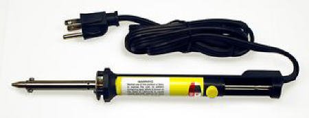
To help with the job, I bought a cheapo vacuum desoldering iron. This makes desoldering of through-hole components easy. Just put the iron over the pin, hold for a second, then press the button to release the plunger and mostly all the solder is sucked up. I used this to desolder the daughterboard too. I had to revisit a few pins to get them totally clean, but overall the process was simple. I don’t do enough desoldering to justify the cost of a fancier desoldering gun with a continuous suction vacuum pump, so this seemed like a good tool for occasional use.
I removed the two SMD capacitors on the daughterboard with a hot air tool. I’m not sure how you would do that without such a tool – just rip them off with pliers? The hot air worked fine, except when I used tweezers to slide off the caps after the solder had melted, I accidentally pushed one of them right through a bunch of other little SMD components, whose solder had also melted, and ended up with a jumbled heap of little components half soldered together in a corner of the board. Ack!!
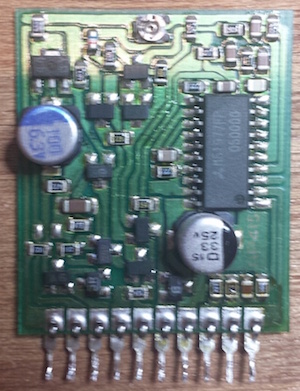
Here’s the daughterboard, before I wrecked it. The four components at bottom right were all pushed into a pile in the corner. A couple of them actually fell off the board, as did one of the pins. But with some patience I was able to separate them all and get things cleaned up, and I think I even put everything back where it was originally. 🙂 After removing the old caps, I cleaned up the board with isopropyl alcohol and a toothbrush to remove the capacitor goo.
The last step was soldering in new capacitors, and putting it all back together. Compared to everything else, that was a breeze.
When the time came for testing, I didn’t take any chances. I brought the whole machine outside, with a fire extinguisher in hand, ready for anything! I plugged it in, pressed the power switch, and… WOOHOO! It booted right up, and everything now looks a-ok. I can boot from the rear power switch or the keyboard power button, and the soft power-off function works again too. I feel like Superman!
This was my first time recapping anything, and I won’t be so timid about recapping next time the need arises. The whole process took about three hours, including lots of futzing around during disassembly and reassembly. If I hadn’t blundered by knocking off a bunch of unrelated SMD parts, I probably could have done the whole job in about an hour.
Read 18 comments and join the conversation18 Comments so far
Leave a reply. For customer support issues, please use the Customer Support link instead of writing comments.
Careful Steve, don’t get too good at it, or you might get folks inquiring if *you’ll* do their recaps. Competition for Charles! 😛
I once had to replace most of the electrolytic capacitors in a TiVo Series 3 power supply. Luckily for me they were all giant through-hole parts, easy-peasy. 🙂
Congrats! For the surface mount caps, the trick I’ve learned from others is to use a pair of pliers, push straight down, then twist…the legs will snap right off. A little flux and desoldering braid followed up by isopropyl alcohol to clean up the flux, and you’ve got clean pads ready to solder new ones in place. As for replacements, I’ve been using MLCC’s – should last longer, and I find them very easy to solder with a normal soldering iron with a chisel tip. Flow some solder onto one pad, place the capacitor, push down with a toothpick, touch the solder blob, and it’s in place. Solder in the other side, the touch up the first side if needed. All done…
How does the solder sucker iron you got work? I got one for Christmas that has the bulb on it, and it seems to be pretty much worthless, which is a disappointment. Doesn’t seem to have enough suction force to suck up the solder…and the tip doesn’t seem to conduct heat well or something…looks like that plunger type might get better suction. I have one of those that is just a sucker with a plastic tip, but it seems to jump out of the way badly when you push the button.
The sucker iron has a plunger that you press down and lock in place. Then when you’re ready, you push a button to release the plunger, and it springs back up and sucks the solder. The tip is like an oversized soldering iron tip with a hole in the center. It doesn’t heat up very quickly, and there were some complaints on Amazon about it not putting out enough heat to melt some bigger joints. But for the price it seems to work well enough, and IMHO is better than a plastic solder sucker combined with a regular iron.
Congratulations on fixing the PSU! I’ve done a few myself, BBC Micros and the like that have let out smoke from Rifa capacitors as well as electrolytics like yours. As for surface-mount parts, the classy way to remove them is to use a Metcal Talon. You need to heat both ends of the part at once, so the Talon is two soldering irons on one handle! They’re hinged inside the handle and wired to the Metcal power unit. That supplies radio frequency power to the iron. But be prepared for a shock when you look up the prices…
Nice job.
There is an upgraded and no so much more expensive ($30 with free shipping) version of crappy chinese desoldering iron with integrated pump on ebay, would recommend it above manual one.
I also prefer to stay on the safe side of the voltage divide, and instead of recapping I’ve swapped guts with a Micro-ATX PSU. Works great as long as you don’t need exotic voltages.
As for desoldering SMD caps, my method is to squish the can a few times with pliers, and then carefully lift it straight up. The can comes off cleanly and leaves two exposed legs that are trivial to desolder with a regular iron.
an 858D+ hot air pencil and a pair of tweezers is how I remove SMD components – larger ones can be done with a very small soldering iron, a flux pen, and some solder wick. With how cheap the 858D+s are on eBay these days there’s no reason not to have one – they’re really good for heatshrink sleeving, too 😀
My hot air tool is also an 858D+, or something that looks almost exactly like it. The problem I had was that I couldn’t easily restrict the heat to a small enough area for just one capacitor, so the solder on all the nearby components melted too. That would have been OK if I hadn’t then accidentally knocked them off their pads, so maybe it’s not really an issue. I used the largest nozzle. A smaller one probably would have helped.
Swapping in the guts of a new PSU is an interesting idea. The +12, +5, and -12 are pretty standard, as long as enough amps are available. I didn’t look carefully enough at the IIsi PSU’s details of the soft power method used to turn it on and off, to see if it could be directly swapped with an ATX type PSU.
The pinout can be found here: http://www.computercraft.com/docs/mchk.shtml
I wouldn’t be surprised if the soft power is compatible with the ATX protocol.
When I did my IIsi, I just wired to a standard ATX female connector. It works well enough, and I didn’t have to recap my PSU. I wish I’d kept it, though
You can desolder two terminals SMDs with two regular soldering irons. Just heat both sides with the irons and move them away from the solder pads.
Steve, do you know the one cardinal rule when working on printed circuit boards with surface mount components?
When heating the board, Don’t Sneeze!
Read IPC-7711B/IPC-7721B.
I also have a IIsi (overclocked, 25MHz, 64M RAM, 8M bootable ROM disk). I mostly use it as my AppleTalk bridge between Ethernet and LocalTalk machines. Thanks for the informative post. I hope mine can be made to keep working for many years too.
@John Honniball; Weller also has nice desoldering tweezers that plugs into any Weller stations.
@Andrew H; The 858D+ hot air gun is an ok entry model for general use but a hot air pencil like the Weller HAP1 HAP200 or WXHAP200 is the way to go for small parts and precision work.
@Wesley; That pliers trick is a great plan to also tear off pads. For desoldering trough hole get a DS80 or DSV80 you won’t regret it.
@Steve; Using the right nozzle for the job will greatly improve your work. You can get sets for next to nothing.
If you are doing much more of this, I’d recommend a Metcal MX500. Used, on eBay, a nice setup will cost you around $200. Perhaps a bit more if you go for the Talon SDM tweezers.
Electrolytics come in different grades. Always replace power supply caps with a part that has a 105 degree rating, not just an 85 degree part.
I found desoldering surface mount caps and resistors easy. Heat one end up with the iron and enough heat will flow through the part to melt both ends free. Then just pick it off with tweezers. Hot air guns will always melt everything within a two inch radius as you found.