

Unidisk 3.5 Daisy Chain, Sad Trombone
The Unidisk 3.5 is an 800K floppy drive for Apple II computers, using the Smartport protocol to communicate with the Apple II. The BMOW Floppy Emu disk emulator is also capable of emulating a Smartport disk, so in theory it should be possible to plug the Emu into the Unidisk’s daisy chain port, and use them both together. Unfortunately it doesn’t work, for reasons that weren’t clear until recently. The good news is I now understand what’s going on, but the bad news is it’s probably impossible to make it work without hardware modifications.
Smartport is a bus-based protocol. Each disk is assigned a unique address at startup, and it should only respond to commands for that address. The original Floppy Emu firmware for Smartport was intelligent enough to do that, but it contained some implicit assumptions that were wrong in a daisy chain situation with multiple Smartport drives present. Fixing those was the first task. For example, it would ACK the receipt of any Smartport command, even if it didn’t actually respond to it because it was for the Unidisk. It would also enable its output on the READ and HANDSHAKE lines whenever any Smartport drive was enabled, interfering with the Unidisk.
Address Assignment
After resolving those problems, daisy chaining still didn’t work. The logic analyzer showed that the Floppy Emu was never even assigned a Smartport address. Here’s the telltale trace:
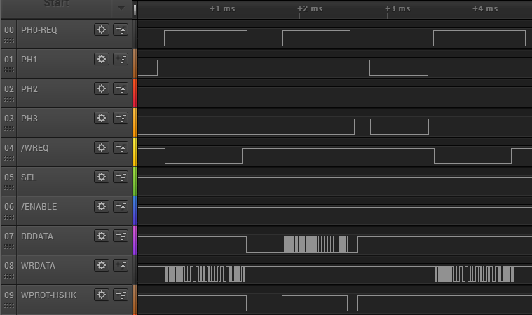
The first set of squiggles there on WRDATA (channel 08) is the computer assigning address 1 to the Unidisk with an init command. The following squiggles on RDDATA (channel 07) are the Unidisk’s reply, which is “OK, and there are no more Smartport devices after me”. The next command on WRDATA is a request to read sector 0 from the Unidisk, so Floppy Emu was completely ignored.
Determining what those squiggles mean is a tedious process. I have to zoom in until I can see each positive and negative transition of WRDATA. Every 4 microseconds there will either be a transition (a logical 1 bit) or there won’t be any transition (a logical 0 bit). I have to write down the bit sequences, frame them properly into bytes, and then consult the Smartport spec to make sense of it all. Maybe someday I’ll write an automated tool to do all this, which would make the debugging process dramatically faster. For now I’m happy simply to graph all the signals, because there was a time when I didn’t have even that much.
So why doesn’t the Floppy Emu get assigned a Smartport address? If I were designing the Smartport protocol, I would probably have it send as many init commands as necessary to give addresses to all the drives. Just keep sending init commands, incrementing the address each time, until all drives have received an address and no more init responses are received. But Apple chose a different solution, where each Smartport device is expected to know definitively whether or not there are more Smartport devices behind it in the daisy chain.
Input Becomes Output
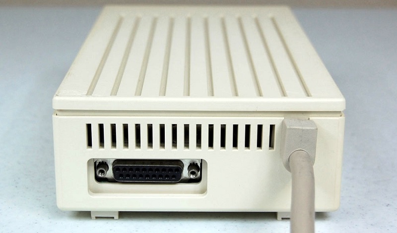
Apple used a sneaky trick to accomplish this. On the DB-19 connector, pin 16 is normally an input to the disk called HDSEL, which is used to control non-Unidisk 3.5 inch drives. But on the Unidisk 3.5 (and presumably other Smartport devices) pin 16 of the male connector is tied internally to ground. On the Unidisk’s daisy chain output connector, pin 16 has a 2Kohm pull-up resistor to 5V. Internal logic senses whether pin 16 on the daisy chain connector is low (another Unidisk or Smartport device is daisy chained, and its internal ground connection pulled pin 16 low) or high (no Smartport device).
Turning a disk input into a direct ground connection is dangerous. It means that if the computer tries to drive a high value on HDSEL, and a Unidisk 3.5 is connected, it will create a power to ground short and likely fry the disk controller. This will happen for certain if a Unidisk 3.5 is connected to a Macintosh. The Apple IIc and the Liron disk controller don’t connect anything to HDSEL, so they’re safe. The Apple IIgs does make use of HDSEL, but its schematics reveal a 470 ohm inline resistor to protect against a power to ground short. I’m not sure about other disk controllers like the Apple 5.25 controller or the Duo Disk controller. The Disk II controller has an incompatible 20-pin connector, but if you used the Floppy Emu’s adapter cable to connect a Unidisk 3.5 to a Disk II controller, it would directly connect +5V to ground. Ouch!
This kind of I/O switcheroo seems like a very bad idea to me. Ideally, you could plug any kind of 19-pin Apple drive connector into any kind of 19-pin controller, and the worst that would happen is it wouldn’t work. But Apple created a situation where you can actually destroy your equipment by doing this. It’s not the first time, either. Pin 4 was similarly repurposed, from a ground connection on Unidisk 5.25 and Unidisk 3.5, to a drive input signal on the Apple 3.5 drive. And pin 10 is a drive input for Macintosh and Lisa, but an output for Apple II drives.
An Unintended Voltage Divider
The Floppy Emu’s CPLD can be reconfigured to treat pin 16 as an output when in Smartport mode, with an output value of zero, to simulate a ground connection. Setting aside the potential for damage this presents to a Macintosh connection, it should get the Unidisk to recognize there’s another Smartport device on its daisy chain connector. Unfortunately it doesn’t work. Ironically it’s the CPLD protection resistors that were added in Floppy Emu Model B that cause the problem, by creating an unintentional voltage divider with the Unidisk’s pull-up resistor on pin 16.
All of the Model B’s CPLD inputs have a 1K series resistor to help protect against voltage spikes and static. This is fine when the inputs are actually inputs:
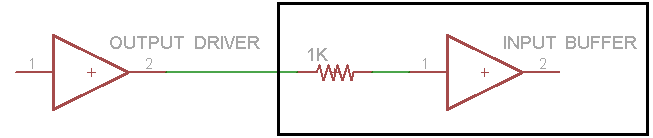
The CPLD input buffer draws only a few microamps of current. From V = IR, we can calculate that the voltage drop across the resistor will be a few microamps times 1K, or a few millivolts total. If the computer drives a 5V input signal, the CPLD will see something like 4.99 volts, which is fine.
Things are quite different when the input becomes an output, and that output has a relatively strong pull-up resistor:
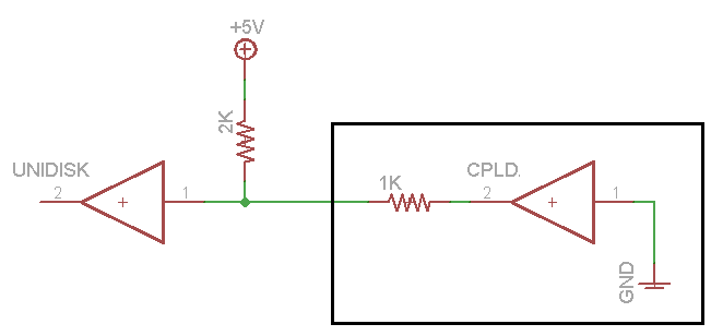
Now there’s a path through the two resistors, from 5V to ground. From the voltage divider rule, we can calculate that the voltage at the point between the two resistors will be 1.66 volts. (I measured it at 1.55 volts experimentally.) That’s far too high to be recognized as a logical zero value; 0.8 volts is the maximum valid zero voltage for 5V TTL logic. So the Unidisk doesn’t think there’s a Smartport device on its daisy chain connector, and the Floppy Emu never gets a Smartport address.
I was able to get daisy chaining working by adding a small value resistor between HDSEL and ground, external to the Floppy Emu. But that’s not much help to anybody, and it also prevents the Floppy Emu from working correctly in 3.5 inch disk emulation mode.
Solution?
So what’s the answer here? I’m afraid there probably isn’t one, and Unidisk 3.5 daisy chaining just won’t work, wah-wah and sad trombone. But maybe a reader will have a clever suggestion.
Changing the Floppy Emu’s protection resistors to something less than 1K could help. My math says a resistor of 381 ohms or less would put the pin 16 voltage at a valid logical zero for 5V TTL. By combining an old Floppy Emu Model A (no resistors) with some manually-wired external resistors, I was able to directly confirm that 1K ohm protection resistors don’t work for Unidisk daisy chaining, but 330 ohm resistors do work. But dropping from 1K to 330 ohm would be a significant reduction in the amount of protection for the CPLD. I’m also reluctant to make any changes to the Floppy Emu hardware design, which has become like a supertanker that’s difficult to change course. Any changes now would cost lots of time and money, and wouldn’t help owners of existing hardware anyway.
Another possibility is some kind of external adapter, with a physical switch for shorting pin 16 to ground. That would work, but the time needed to design, build, and stock such an adapter would be too high relative to the importance of Unidisk 3.5 daisy chaining. It’s unlikely that many people would be interested in buying such an adapter.
Read 15 comments and join the conversation15 Comments so far
Leave a reply. For customer support issues, please use the Customer Support link instead of writing comments.
The number of times Apple changed the meanings of pins on its floppy controller is insane. I remember back in the 90s memorizing what combinations of drives would work with different floppy controllers. I seem to have since repurposed that block of memory in my brain. Luckily Google is there whenever I ever need to know.
* or changed the rules for SmartPort. I think that was why the DuoDisk 5.25 didn’t work on the last few Apple II models.
Interesting stuff!
Only one protection resistor needs to change to 330 ohms. All of the other pins can stay 1K.
Furthermore, 330 might be adequate protection. What’s the absolute maximum rating for pin current on the CPLD? If it’s 20 mA, for example, that tells you that worst-case, you won’t damage the chip with 20 mA flowing into the ESD protection diodes. Ohm’s law says that’s 6.6V across the resistor, so pin 16 can go from -6.6V to VDD+6.6V without damaging the CPLD. Do you expect spikes bigger than that on 5V logic lines?
Sure, 1K handles a wider range without damage, so even though you probably don’t need 1K on the impression, you might want to go with 330 ohms on only the pin that needs it.
“Impression” should be “input”. Autocorrect strikes again.
I wish I could calculate exactly what protection resistance is needed in order to be safe, but I can’t. The datasheet is silent on this point, and doesn’t even mention the word “diode” anywhere. A small but noteworthy number of Model A boards suffered long-term failure that I suspect was due to latch-up, rather than damaged ESD diodes. The 1K resistors in Model B reduced that failure rate to zero, but the 1K value was picked out of nowhere, and might be far more than necessary or just barely enough. I’m not even sure if the resistors help because they limit the current, or because they slow the voltage swings by forming a parasitic RC circuit with the trace’s stray capacitance.
My best guess is that unprotected Model A inputs were damaged when 5V inputs were applied before the Emu’s 3.3V power supply was fully on. The 5V tolerant inputs are only 5V tolerant if the power supply is at least 1.5V. For a brief instant during hot-plug events, this rule may have been violated. But even if that’s correct, it’s unclear what level of current (if any) is safe when that rule is violated.
True, not all of the resistors would need to change to 330 ohm. But they’re in 4-up modules, so I would have to replace four of them (or revise the board). And if 330 ohms isn’t enough protection, it won’t really matter that some pins remained protected at 1K while others were damaged at 330. So hopefully that explains my reluctance to mess with the values. 🙂
To reduce resistance, you can always strap a resistor in parallel. e.g. 470 ohms in parallel to the existing 1K gives you about 320 ohms. That may be easier to hand-patch.
If you have a spare output pin left on the CPLD, you could use it to drive the problematic Apple pin. Maybe don\’t drive it directly, but use a FET. As there is a pull-up, you just have to drive the pin low.
If you have two spare output pins on the CPLD, you could use something like a SN74LVC1G125 (single buffer with output enable) to either leave the Apple pin in input mode (buffer output disabled) or to drive it low or high. With proper driving signals for the buffer, you should also be able to emulate an open collector signal (disabling the output instead of driving it high).
I wish there were a way to make Unidisk 3.5 daisy chaining work for existing Floppy Emu boards. The best solution I can think of is to hack the 20-pin ribbon cable that’s connected to the Emu, like this: connect a switch and a 330 ohm resistor in series between the cable’s pin 1 (ground, the wire with the red stripe) and pin 12 (HDSEL, the 12th wire counting from the red stripe). When running the Emu in Smartport mode, close the switch, so it pulls HDSEL to ground. When running in other modes, leave the switch open. If you accidentally put the switch closed when it should be open, it shouldn’t harm anything, but the disk may not work correctly.
Going forward, the simplest solution is obviously to change the value of at least a few of the protection resistors. This could be done with the existing PCB design, with a single component substitution for one of the resistor packs. The question is what this means for protection. Maybe I’ll hand-build one this way, and then intentionally hot-plug it a few hundred times to try to induce a chip failure, to see if 330 ohm is still sufficient protection.
Tangentially related question: what are you using for logic analysis? Dedicated analyzer of some description?
I have several different logic analyzers, but I mainly use the Saleae Logic. It did a review of it here a couple of years ago. It lacks a few advanced features, but to be honest I never miss them, and it’s super easy to set up and use.
I can confirm that plugging in the wrong drive to the wrong port/controller will indeed burn up chips on both controller and drive. I can not recall which combinations produced smoke but I do remember installing chip sockets and new chips…
Not having much electronics knowledge, I tried something more primitive.
Modifying a ribbon cable is unpleasant so I decided on a mod to the Floppy Emu DB-19 adapter board.
The DB-19 #16 to header #12 trace was cut and wires soldered to them. A wire was run to header #1 (GND). This was done entirely on the bottom of the board.
Testing was done with ProDOS 2.4.1 and Copy ][+ 8.4.
Connecting DB-19 #16 to header #1 was tested with a UniDisk 3.5 and the Floppy Emu in SmartPort mode with 3 volumes. This worked fine on a //c ROM 0, IIgs ROM 3 and //e enhanced with Liron card. The //c+ had an odd glitch (asides from needing a Open Apple-Reset on a powerup); it only found the first 2 volumes on the Floppy Emu. Likely another odd //c+ bug.
Connecting DB-16 #16 to header #12 and Apple 3.5 drive mode worked fine.
Header pins will be added to the wires allowing for a jumper to set normal or SmartPort-mode-daisy-changed-to-SmartPort-Bus-device selection.
I would recommend connecting to GND with a low-value resistor like 330 ohm, instead of directly. That will limit the current and protect your computer from damage if you accidentally leave your jumper in the wrong position when connected to a computer that actually uses HDSEL.
With the demise of Radio Shack, getting components locally has gotten difficult. I tried the brutal approach because I had the materials available.
At least that left me in a position to easily try a resistor.
A 324 ohm resistor was purchased from a surplus store. Various combinations worked until a //gs ROM 3, Apple 3.5 and Emu in 3.5 mode. Reads from the Emu failed.
I’m unlikely to connect an Emu to the external drive port of a Mac (I’m pretty sure that every Mac in the house has Ethernet) so will probably go ahead with a jumper on the Emu’s DB-19 board.
The reason why even the oldest Mac in the house has Ethernet was in case I wanted to read Apple II 3.5 disks. Fortunately the Emu helps avoid getting another vintage computer running. (The ProDOS FST only seems to work on 68K Macs.)
@AVRKiller, ProDOS support does work on PowerPC machines via the PC Exchange control panel, but the floppy drives tend to be flaky with dealing with 800k disks. Later versions of MacOS also have a weird limitation that they won’t mount ProDOS disks unless network file sharing is turned off.