

Apple IIc Internal/External Drive Switcher
If you’re using a Floppy Emu disk emulator with an Apple IIc, you’ll want to see this: a switched adapter that can reassign the external 5.25 inch drive as internal, and the internal 5.25 inch drive as external. This little gizmo helps to work around the Apple IIc’s inability to boot from an externally-connected 5.25 inch drive. That shortcoming is a headache for 5.25 inch disk emulators like Floppy Emu. With this internal/external drive switcher, the limitation is now gone!
Background
The IIc has an internal built-in 5.25 inch floppy drive. The internal drive appears to the computer as slot 6, drive 1. If you connect an external 5.25 inch floppy drive, it will appear to the computer as slot 6, drive 2. Unfortunately the whole Apple II family is designed to check for a bootable disk in drive 1 only. The computer can boot from drive 1, and then use drive 2 as a secondary disk, but it can’t boot from drive 2. So for the IIc with its built-in drive 1, this means it can never boot from an external 5.25 inch drive.
An important detail: this limitation only applies to the Apple IIc with an external 5.25 inch drive. An external Smartport drive (like Floppy Emu when configured for Smartport hard disk emulation mode) appears to the computer as slot 5, drive 1, and is bootable.
Apple IIc owners who want to boot from an emulated 5.25 inch disk image are in a difficult spot. Until now, their best option has been to remove the top panel from the IIc, disconnect the internal floppy drive, and connect the Floppy Emu to the internal drive connector on the motherboard. This works fine for the Floppy Emu, but it means IIc owners forfeit their ability to use the internal drive.
How the Drive Switcher Works
There’s almost no difference between the internal drive connector on the motherboard and the external drive connector at the rear of the Apple IIc. Although they’re different shapes and even have different numbers of pins, they feature the exact same disk IO signals except one: the drive enable signal. To perform this drive switcheroo, the adapter needs to tap into the signals from the motherboard, divert the enable signal externally, and route the external enable signal back inside to the internal drive. This is easily accomplished with some headers and wires and a slide switch, but the tricky part is making it all small enough to fit inside the Apple IIc case.
A slide switch makes the drive remapping optional. At one switch position, the external drive will appear as drive 1 and the internal as drive 2. At the other switch position, the internal drive will appear as drive 1 and the external as drive 2. Now Apple IIc owners can have the best of both options.
The Hardware
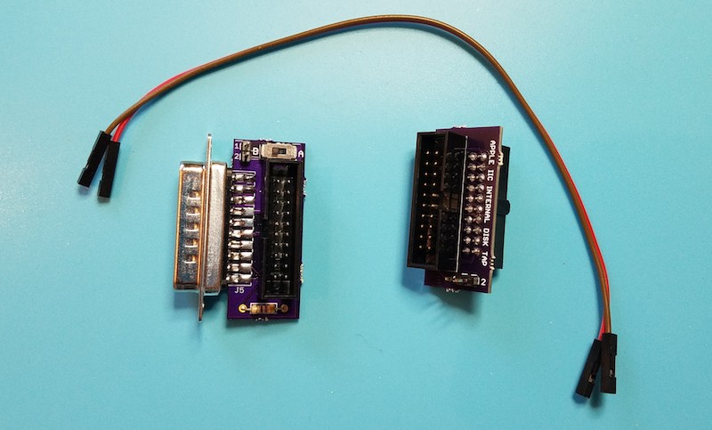
This is a two-part device: a signal tap that should be installed inside the Apple IIc, and a modified DB19 adapter with a slide switch for the external connection. Two female-female jumper wires are passed through a gap in the case to make the connection between the two parts.
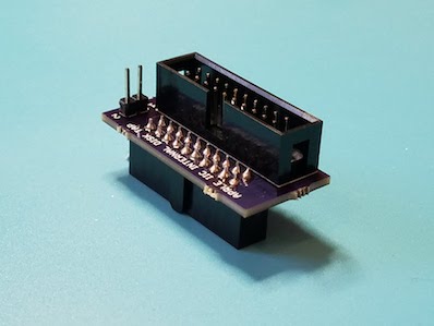
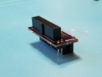
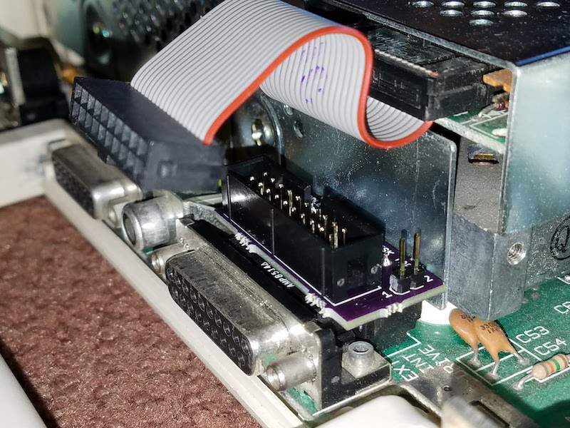
The signal tap portion of the drive switcher looks a little peculiar, and it’s a minor challenge to solder closely-spaced through-hole components to the top and bottom of a PCB like this, but it works. The top is just a standard 20-pin male shrouded header, with a polarizing key like the one used on Apple drive cables. The bottom is a PCB-mounted female version of the same connector – not a very common part, but fortunately Digikey has it. The only other component here is a 2-pin male header for attaching the jumper wires.
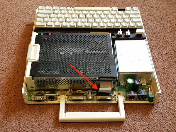
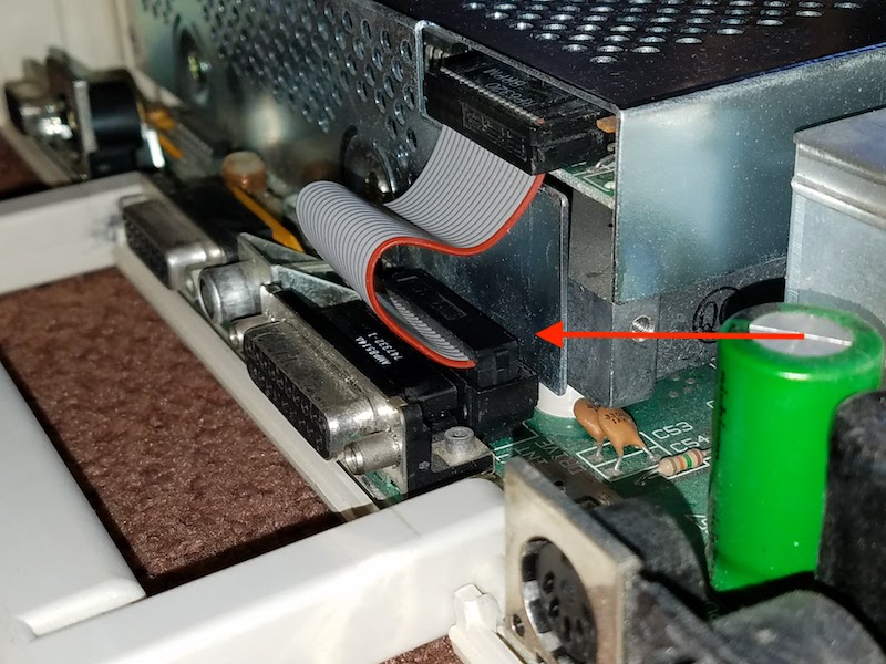
Step 1 is to remove the top panel from the Apple IIc (follow the instructions here), and locate the ribbon cable that connects the internal floppy drive to the motherboard.
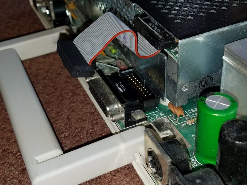
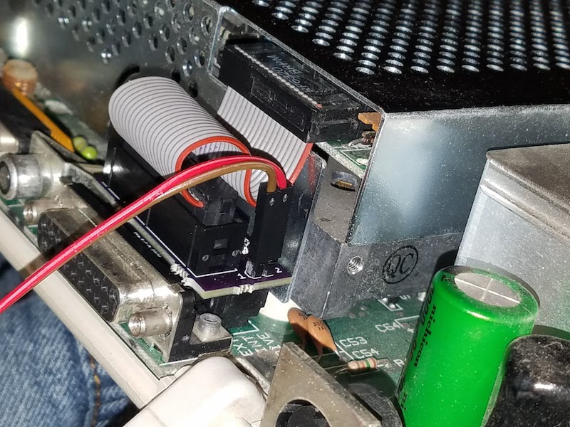
Disconnect the ribbon cable from the motherboard, and plug the signal tap into the motherboard in its place.
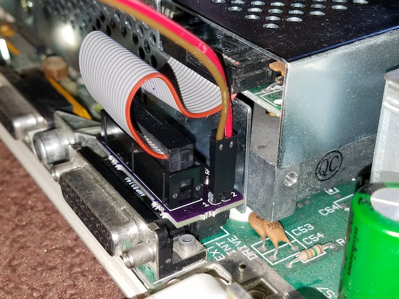
Then plug the ribbon cable into the signal tap. Also connect one end of each jumper wire to one of the signal tap’s male header pins. Here I chose to connect the brown wire to pin 1, and the red wire to pin 2. I’ll need to make the same choice later for the external jumper wire connections.
Before closing the case, it’s important to squish the ribbon cable down into the gap between the signal tap and internal floppy drive bracket. Push it down as far as it will go. This will make it easier to fit the top cover back on later. Notice the difference between the ribbon cable position in this photo as compared to the previous one:
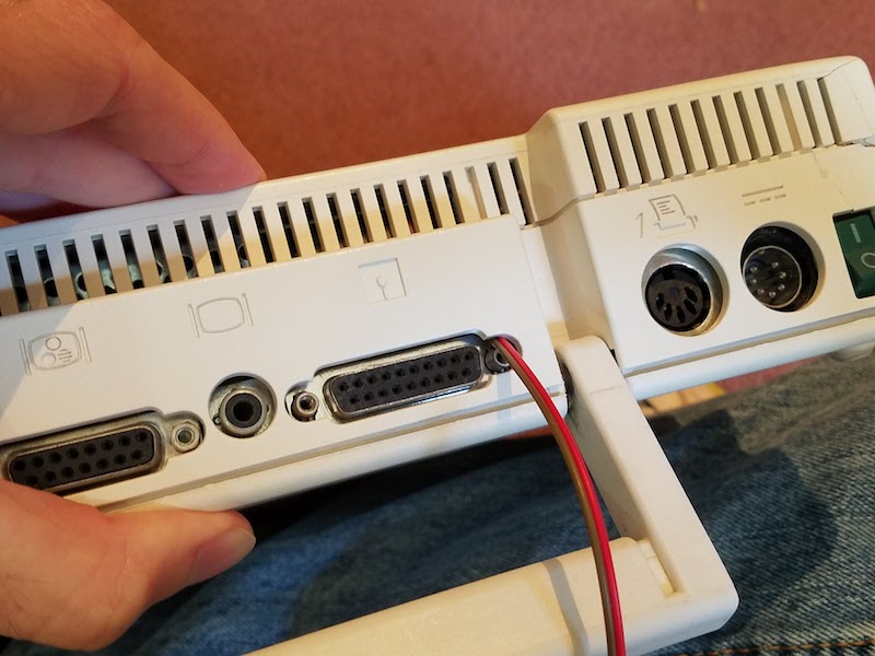
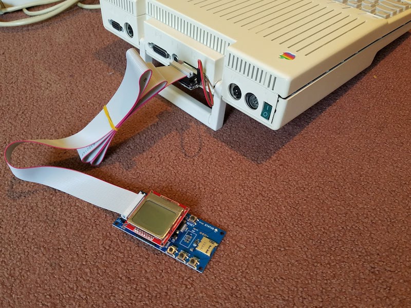
Now it’s time to close the case. First, set the top panel loosely on the IIc, and thread the jumper wires through the opening for the disk connector in the rear of the case.
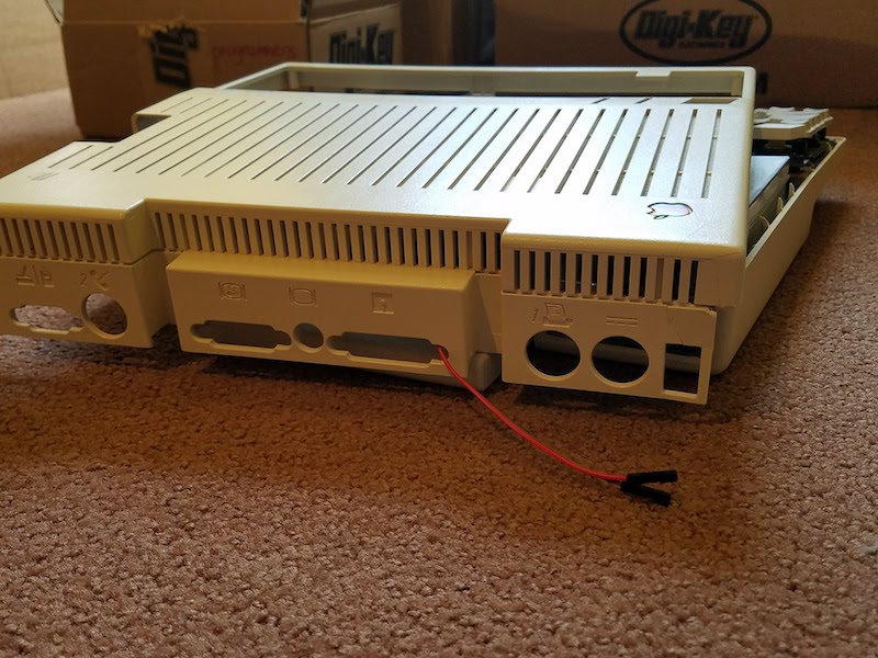
Then reinstall the top panel. It’s a snug fit, but there’s a large enough gap between the top panel and the rear connectors for the jumper wires to squeeze through. As an alternative, the jumper wires can also be threaded through the opening for the printer port or the video connector. After the top panel is reinstalled, it should look like this:
Connect the jumper wires to the 2-pin male header on the switched DB19 adapter, remembering to use the same color-to-pin mapping as before. Then plug the DB19 adapter into the Apple IIc’s external disk port. It will replace the standard DB19 adapter that’s included with the Floppy Emu.
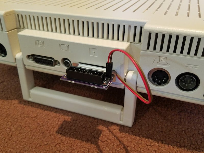
Finally, connect the Floppy Emu’s 20-pin ribbon cable to the switched DB19 adapter. All done! This Apple IIc can now boot Choplifter and other 5.25 inch disk image favorites from the Floppy Emu, while retaining the internal 5.25 inch floppy drive for secondary needs like disk copying. Or at the flick of a switch, the IIc can be restored to normal operating, with the internal floppy drive configured as the boot drive.
Coming Soon
I hope to have the IIc Internal/External Switcher ready for the BMOW store in a month or two. There are still a few wrinkles to iron out before it’s ready. Because it’s such a tight fit inside, I need to get feedback from some other IIc owners to verify the switcher fits their computers too. I also want to revise the PCB a bit, to make the switcher easier to assemble. And I’d like to provide more meaningful labels for the switch positions than simply “A” and “B”. If there were enough space, I’d label the switch positions something like “normal” and “swapped”, but the adapter is so small that there’s only room for 1 or 2 letters at most. Any great suggestions?
Read 14 comments and join the conversation14 Comments so far
Leave a reply. For customer support issues, please use the Customer Support link instead of writing comments.
Perhaps an icon like 🔀 to indicate the swapped position.
“=” for straight, “X” for swapped?
I just ordered the bundle for my //c and would be interested in the adapter when available. Thanks!
I have a IIc with a malfunctioning internal drive, so this sounds perfect for me. I’d volunteer to be one of your testers, but I don’t have a Floppy Emu yet, haha. If I can help somehow anyway, let me know!
N for normal and S for swapped?
The new version is off to the board house. I adopted Tim and Alex’s suggestion of an icon showing parallel lines for normal mode, and crossed lines for swapping.
Very great design! I will definitely be interested in ordering one when available. The only other option I had to boot without opening the case was breaking into the command line and manually telling it to boot from the other drive.
This will certainly be better than what I’m doing now which is sorta what john is doing, I am using rom 4x (http://apple2.guidero.us/doku.php?id=projects:rom_4x_and_5x) which is better than all the other roms as you can boot from either drive seamlessly by pressing a button. But most software doesn’t like that, so this would be much better. Sign me up!
Sounds very nice! Right now I am using the A/B switcher from bmow and it works great. I can swap between the Floppy Emu and the internal drive with a switch. It doesn’t do anything to the external port, so I just leave my second drive connected to it, or I move the Floppy emu to it if I want to use it in Smartport mode. With the new switch, I could switch between smartport mode and the internal drive mode without having to disconnect anything unless I wanted to use my external drive. As a suggestion for the future, it would be cool if there were two ports on it so I could hook up my external drive and the floppy emu and switch between internal and smartport mode for the floppy emu and the second port would switch between external single drive and external daisy chained drive.
Interesting – how exactly are you using the A/B switch? Do you have a photo you could share? Did you remove your internal floppy drive from the IIc case? Or do you have a ribbon cable running from the motherboard to the A/B switch, and a second ribbon cable running from the A/B switch back inside the IIc case to the internal drive? Or something else maybe?
I removed the short internal drive cable and hooked it up to the Floppy Emu, so the floppy Emu has a very short cable on it. I then took the two long cables that came with the Floppy Emu and the A/B switch and put them both through the top part of the aux/monitor port between the plastic and the metal connector and connected one to the motherboard and the other to the internal floppy. So, I end up with two long cables connecting out through the A/B switch and fortunately it works without being too long. If I want to use it in Smartport mode,I unplug the Floppy Emu from the A/B switch and hook it onto the external port with the short cable. Here are some pictures: https://imgur.com/a/2U3OvJ5
Just some further clarification for my idea of the future version of your new switcher: You could theoretically get two Floppy Emu’s and hook them up externally. In the first mode, one Floppy Emu would be the boot drive, the other would be a smart port drive, and the internal floppy would act as the external drive. The internal drive acting as an external and the smartport drive would be daisy chained. This would be the perfect scenario because it would allow you to use the internal drive as an external for your save games onto a real floppy for things like King’s Quest, and still allow you to have a smartport drive connected at all times. With my current solution, I use my real external drive for my save games. With your current solution, I could use my internal drive for my save games and wouldn’t need an external drive at all.
Switching the mode on my idea of the future version, the internal drive would be the boot drive like normal, the two ports on the external drive could be hooked up to the Floppy Emu running as a smartport HD and you could also hook up a real external drive or another Floppy Emu as a daisy chained external drive.
Finally, there might be a way to update the firmware to recognize the switch position and automatically switch the Floppy Emu from Smartport mode to 5.25″ mode when it is being used as the internal drive.
When will this be available??! Would love to buy one!
You can buy one from the BMOW Store.