

Where Did All The Watts Go?
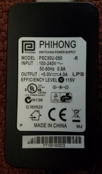
How efficient is a typical 5V AC-to-DC power supply? I’m digging through my box of assorted power supplies from past projects, looking for something appropriate for a large LED matrix, and noticed the one pictured above. 110V 0.8A input – that’s 88 watts. 5V 4A output – that’s 20 watts. Is the power supply really only 22.7% efficient, or is my reasoning flawed somehow? I would have expected a switching power supply like this one to have much better efficiency than that. A quick search for information on “level IV power supplies” suggests they must be 85%+ efficient, so something doesn’t add up.
Read 12 comments and join the conversation12 Comments so far
Leave a reply. For customer support issues, please use the Customer Support link instead of writing comments.
If I remember correctly, the input specs are the inrush and startup current, or sometimes the absolute current you can get the device to pull (say with a shorted output), not the current at rated load.
I may be off base, this was a year ago, and I never was seriously involved with the certification and labeling to know everything about these labels.
Yes, after doing some reading on this question, I think you’re right. The “0.8A” probably means the instantaneous input current might be as high as 0.8A. But that doesn’t mean the RMS input current is 0.8A or that the input power is 88W – both will be lower.
The purpose of this exercise is to determine how large a power supply I need for a 64×64 RGB LED matrix. Right now I only have a 64×32 RGB matrix, and the 5V 4A power supply pictured above. Measuring with a Kill-a-Watt meter, when I display a test pattern where every LED is maximum white, the power supply draws 24W from the wall (0.34A and 123V AC according to the Kill-a-Watt, and yes 0.34A times 123V does not equal 24W, why?). Assuming pessimistically that the power supply efficiency is 65%, then that 24W input power results in 15.6W output power, which at 5V DC means 3.12A DC. To run two of these LED panels to make a 64×64 matrix, I would therefore need a power supply capable of delivering at least twice that much current: 6.24A at 5V DC.
It would be much simpler to use a multimeter to measure the DC current directly, instead of a Kill-a-Watt to measure the AC power combined with guesses about efficiency. But I’m slightly afraid of blowing up my meter or melting a wire. I guess 3.12A DC isn’t really that much though… I’ll try it.
OK, here’s the DC current draw from the 64×32 RGB LED panel, measured with a multimeter, for a few test images:
animating flag: 0.7A
BMOW logo: 0.79A
half white: 1.88A
all white: 3.24A
“and yes 0.34A times 123V does not equal 24W, why?”
Power factor – Switchmode power supplies are ‘reactive loads’,they don’t draw energy consistently throughout the AC sine wave. Power factor is a measurement of how far out of phase the current waveform of a device is from the A/C voltage waveform; Your kill-a-watt should have a power factor readout, and I’d wager it’ll read about 0.6-0.7 on that PSU.
If you’ve ever wondered why UPSes are rated in VA (Volt-Amps) instead of watts, this is your answer; If something has a power factor of 0.5 and is drawing 50 watts, it’s drawing 100 volt-amps, because it’s drawing all its power during the first half of the sine wave then switching off for the rest. It still averages out to 50 watts, but it’s actually drawing 100 watts 50% of the time – so your UPS has to be able to output twice the “wattage” that the device needs.
It gets much more complicated than that – A/C power is a nightmare to wrap your head around – but in the case of AC-DC switchmode PSUs like this, their power factor is typically atrocious because they charge up their input capacitors during the first half to two-thirds of the sine wave, then draw no current until the next time the voltage crosses zero (because the input caps are full)
More expensive supplies have power factor correction built in, and nearly all modern PC PSUs do – it’s effectively a current smoothing circuit, which actually has the bonus effect of correcting power factor for other devices plugged into the same powerboard/outlet/circuit to some degree.
If you’re at 3.24A all white on half the panel, I’d be going for a 10A-rated cheap eBay/AliExpress supply – applying the usual derating factor (60%) and assuming you’re not going to run it solid white much/at all. That, or a proper Meanwell enclosed-frame 5V10A unit (some AC wiring required): https://bit.ly/2HBM1dy or one of their downlight-transformer-style potted 8A units: https://bit.ly/2l2kJEe (might be a bit close to the limit, but again, you’re not going to leave the panel on full white much/at all)
I had some good links on power factor, but I can’t seem to find them anymore. Apologies; if I can dig them up I’ll make another comment…
Here’s some useful stuff, shamelessly stolen from wikipedia/google images – also, made a small error above, switchmode PSUs draw power at the *peak* of the sine wave and typically have power factor that gets better as you load them down further.
Power factor of 1 (pure resistive circuit, e.g. incandescent lightbulb): https://en.wikipedia.org/wiki/File:Power_factor_1.svg
Voltage and current are in phase, so here VA = W.
Voltage and current waveforms of a PC PSU without power factor correction (current in blue, PF about 0.75): https://upload.wikimedia.org/wikipedia/commons/3/3f/Power_factor_75.jpg
The current waveform is non-sinusoidal (because it’s feeding a bridge rectifier and a bunch of tank/input capacitors) so the power factor is less than 1; it draws most of its power during the higher-voltage parts of the waveform, when the input voltage exceeds the current voltage across the input capacitors.
https://en.wikipedia.org/wiki/File:Power_factor_0.svg this is an extreme case of current being completely out of phase with voltage – total actual consumed wattage here is zero over the course of the wave, but there’s still volt-amps flowing.
Also, a Vicor post that might be a little technically-heavy but has some good info: http://powerblog.vicorpower.com/2013/02/what-does-power-factor-mean-and-why-must-we-correct-it/
I’ll stop spamming your comments now!
Great info, thanks a lot. I agree those two PSU options look reasonable.
As to the more interesting question of power factor, I came across the concept in some earlier reading, but am still struggling to understand it fully. Your explanation of “drawing 100 watts 50% of the time” is a good one, but I’m still not entirely clear. Is a low power factor “bad” in some sense? It doesn’t seem to represent a loss or inefficiency, and my electric utility bill won’t be negatively impacted by a low PF (or will it?). Some of the explanations that I read mentioned “usable” power, which seems like a strange concept. As far as I understand, the only drawback of a low-PF device is that it will require heavier-gauge wiring and higher-rated components than a high-PF device consuming the same number of watts, because the instantaneous currents will be higher.
The example with PF = 0 is especially curious. It appears that net current is zero, and presumably there would be no affect on my electric meter or utility bill if I plugged in such a device. Nevertheless, instantaneous current is still flowing.
To steal from Wikipedia – a load with a low power factor draws more current than a load with a high power factor for the same amount of useful power transferred. The PF=0 example would still result in full current being drawn, but zero useful power is actually delivered to the device – I’m not sure such a thing could exist in reality, but it’s fun to think about.
Low-PF devices can seriously screw up generating and distribution equipment – the power that’s not delivered to the device is converted into heat in the generation/distribution network, and in some cases can even be bad enough to knock the 50/60Hz waveform in a small area out of sync with the rest of the grid, which is… very bad.
The wikipedia page is a great place to start, but don’t expect it to make a huge amount of sense – I’m a qualified electrical engineer and it still confuses me.
-[It doesn’t seem to represent a loss or inefficiency… As far as I understand, the only drawback of a low-PF device is that it will require heavier-gauge wiring and higher-rated components than a high-PF device consuming the same number of watts, because the instantaneous currents will be higher.]-
The current is higher instantaneously, but the power dissipation in the wiring (=I²R) will be higher *on average*, not just instantaneously.
For simplicity, thinking of a switched DC system at constant voltage (e.g. a DC-DC switchmode converter), we can keep the same average current by using double the current for half the time. But doing this multiplies instantaneous power losses in the wiring by 4 (due to the squared term in P = I²R term), which (compensating for the fact that this power loss occurs only for half the time) means that the average power loss in wiring etc. is doubled.
-[my electric utility bill won’t be negatively impacted by a low PF (or will it?)]-
Not for domestic supplies, but industrial customers are often billed extra for a low power factor, due to the extra I²R losses in the transmission network.
If you want to measure DC current, you could try a clamp meter (just be aware than not all can read DC current). Recently picked up an inexpensive one on Amazon to troubleshoot what was draining the battery in my vehicle. Clamp it across the positive wire only, and you get a reading. It’s not the most precise, as it has a 40 and 100 amp range, with two decimal places, but would give you some idea…
I like to use automotive fuses as ammeter shunts in low voltage circuits. Pull up a chart from here: https://www.powerprobe.com/fuse-voltage-drop-charts/ Check out their test equipment offerings and then grab a DC volt meter. The creative among you are already thinking about using this idea in your next power measurement project!
All your watts are stolen by chinesium.