

Atmel ICE Wiring Horror
The Atmel ICE programmer/debugger has its SWD connector pins reversed from the standard ARM Cortex debug connector. Arghh… why? It’s the same physical connector (5×2 0.05 inch polarized male), but the pins are rotated 180 degrees from the standard, as if the cable were plugged in backwards. Incredibly, it also ships with a 180-degree reversing cable, so it works – as long as you use their cable. It’s not a mistake: the product is actually designed around a reversed connector with an un-reversing cable.

WHO BUILDS A PRODUCT THIS WAY?? I shake my fist at you, Atmel hardware designer. This is like designing an electric outlet where 110V and ground are swapped from their normal locations, but bundling it with an appliance cord that unswaps them.
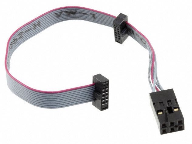
The problem began when I grew tired of Atmel’s tiny 4-inch cable, and decided to get a replacement cable. Naturally I used a standard 10-pin ribbon cable with 5×2 0.05 inch connectors on each end: Adafruit’s purpose-made SWD cable for ARM development. I couldn’t understand why it didn’t work, and why strange things happened when it was plugged in.
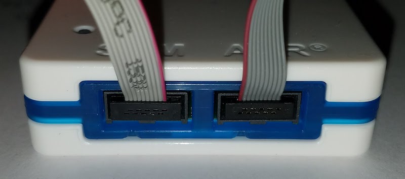
After scratching my head for a while, I noticed something odd. The title photo shows both the original cable and the Adafruit cable connected to the Atmel ICE. Notice how one has the red stripe on the right, and the other on the left? Ouch!
From looking at the original Atmel cable, it’s not at all obvious that the pins are reversed. It looks like a straight-through cable, because each connector is crimped straight on to the 10-pin ribbon, with no crossing wires. But a more careful inspection reveals that one of the connectors is crimped on so it’s facing the opposite direction of the other, resulting in a 180-degree rotation of the pin assignments. It violates the rule of the cable’s red wire indicating the location of pin 1. (Ignore the extra 6-pin header, which is used for other devices)
The good news is that there’s no permanent damage to my ARM board. The bad news is that I still need a replacement cable, but now I need to build a reversing one.
Read 18 comments and join the conversation18 Comments so far
Leave a reply. For customer support issues, please use the Customer Support link instead of writing comments.
You should be able to pop the IDC connector off the end of the cable you got from Adafruit, flip the connector 180 degrees, then either press it into the exact same position it was just in, or trim the cable about 5/16″ and press it back in.
That, or just trim the alignment peg off one of the connectors. Standard-density IDC connectors are nice and simple to reposition on ribbon cables 🙂
looks like, that some idiot doesn’t reverse connector when tracing pcb, no one finds it, *k boards are manufactured, just trash it? no way, order cables and sell it!
Yup, I suspect Savant is right about how this happened! Andrew’s method of flipping the connector worked for me, although it was a decent dexterity challenge to release the lock tabs and separate the two halves of the IDC connector. These 0.050 connectors are one-eighth the size of normal connectors.
Hmm, after yesterday’s backwards cable episode, I’m now getting frequent “Verifying Flash…Failed!” errors when programming the chip. It’s the same with the new or old cable. But it’s strange: it’s always at the same address, with the same expected vs actual value, repeatable 100% of the time if I keep trying it, even if I slow the programmer’s interface clock way down. But if I make a small change to my code, and try programming again, it will often succeed. Then after more code changes the verify error will reappear at a new address, but with the same expected vs actual value.
Curious… Atmel Studio 7 generates both an .elf and a .hex file for programming. When you open the Device Programming dialog, the .elf is the default, and it works for programming the ARM, but depending on the program code it also sometimes results in a “Verifying Flash…Failed!” error. If I program the same code to the device using the .hex file, it works fine with no verifying errors. I’m not sure what’s going on here, but it doesn’t seem to be a damaged chip.
Edit: seems to be a bug in Atmel Studio 7, or somewhere in Atmel’s software toolchain: https://community.atmel.com/forum/verify-flash-failure
Steve,
Try if erasing the flash makes any difference to the rate of successful/failed programming attempts.
Regards
I know it is very suspicious that it started happening when you built the other cable, but give that you see the same behavior with an old cable too – it might very well be a coincidence.
Set “Project Properties->Tools->Programming Settings: Erase Entire Chip”. And set the “Preserve EEPROM” checkbox (just in case you have some calib, stat or settings data there).
Its not Atmel anymore. It’s Microchip and they have been crazy for years, including the MPLabX bloatware.
Just did the same thing, I fixed mine by cutting the notch off the plug and super gluing it to the other side, thanks Andrew H for the idea. another idea I were thinking was to try to remove the plastic of the plug on the programmer and revers it, or cut a 2nd notch in that
Alternative strategy, break-out your programming lines and throw that stupid cable in the trash! https://swharden.com/blog/2023-08-22-avr-ice-power/
Hi,
This is from a novice and the below applies to breadboard connections.
Bought:
1) Atmel-Ice-Pcba without cables for $99 from Mouser
2) IDC Ribbon Connector Flat Ribbon Cable Jtag Cable 1.27mm Pitch 2 Row 10 Pins Connector Female to
Female Wires SWD Cable Length 200mm/7.87 for $10 from Amazon
3) Proto-Advantage DR127D254P10M Dual Row 1.27mm Pitch 10-Pin Male Header to DIP-10 Adapter for $15
from Amazon.
Connected the cable to AVR port with red wire on the left with AVR port facing me. Connected the other end of the cable to the adapter pins with the red wire on pin 9 on the adapter as shown below:
Red
| | | | |
9 7 5 3 1
10 8 6 4 2
The idea is that red wire need to be connected to one of the end pins on the adapter and that pin becomes the number 9 because you have connected the other end of the red wire to pin 9 of the AVR port. Next, pin 3 on the adapter is for GND, 4 is for VCC and 3 is for UPDI. Connect pin 3 to UPDI pin of the MCU.
Correction to above: The red wire goes to right of the AVR port facing us.
Thank you for this! Hours of pulling my hair out, and you had the answer I needed. I used the “clip the notch” method mentioned.
You are welcome! Glad it helped!
Yes, perverse. I take a regular adapter, desolder the 10-pin, and mount it to the other side of the adapter board… voila. Worse yet, the stupid micro/mini/wtf USB connector on the ICE sucks a bag of DEADBEEF. Very tempted to solder the wires to the board… somebody stop me.
I’m here only since I was searching for some back story to the crazy 6 pin mirror numbering. They refer to the contact with the little arrow, the one most would call “1”, number 5. I suspect the designer of one end was mocking the designer of the other.
I wasted a few hours on this issue, until I opened the Atmel-ICE, and noticed that the ‘1’ on the connector was opposite site of the red wire of the flatcable… This triggered my suspicion and after a google search I found this page. Thanks to the author, cause it allowed me to finally fix it and assemble a working cable between Atmel-ICE and my target HW.
To Atmel : if you do this kind of counter-intuitive stuff, at least document it clearly. The whole Atmel-ICE datasheet does not contain a single photo, indicating which is pin 1 on the device’s connector. Bad karma will be yours.
I tripped-over this *again* this evening. It’s been a few years since I had a naked AVR in the bench and I’d forgotten #SMH
@Pascal re: bad karma for Atmel, well, they did get bought by Microchip