

PCB Autorouting
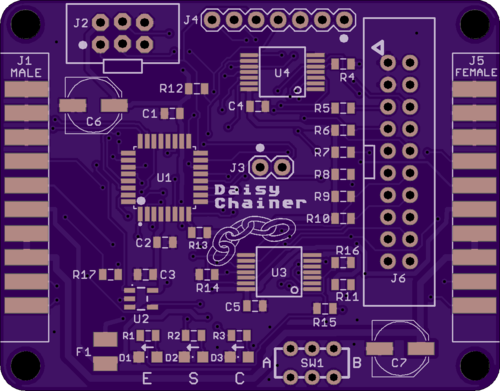
The Apple II Daisy Chainer for Floppy Emu is done, and I’ve ordered a few PCBs made for testing. This proved to be a surprisingly challenging board to lay out and route the traces. It’s a simple two-layer board, and I wanted to keep it as small as possible, so the signal routing quickly became very congested. Hand-routing of the first 40 traces took almost a whole day of tedious work, so I finally gave up and tried autorouting the remaining 80 traces. And it worked! The result looked pretty good, too. I’m curious to know how autorouting has turned out for other hobbyists. Have you ever autorouted nearly an entire board? What were the results?
I haven’t had good results with Eagle’s built-in autorouter, so for recent projects I’ve been using a stand-alone autorouting software package called Freerouting. It’s a Java-based app with a slightly awkward UI, but it’s impressively powerful. First you export your Eagle board file in .DSN format, using a script provided by Freerouting. Then you import the DSN file into Freerouting and let it work, running for about 1 to 15 minutes. When it’s finished you can export an Eagle session script, which will rip up all your old tracks and lay down the new ones calculated by Freerouting.
Obtaining good autorouting results requires careful setup of Eagle’s design rules. For example, the default might be to use 8 mil traces with 8 mil minimum spacing between traces, but power and ground might be treated as a separate net class requiring 20 mil traces for extra current-carrying capacity. The design rules also define what size drill to use for vias, and how close to the edge of the board it’s OK to route traces. The autorouter takes all of these constraints into account when it does its job.
So what’s not to like about the autorouter? Can a skilled human do a better routing job? Why not autoroute everything? Here are a few drawbacks that I found.
Fixed Component Placement – When I route by hand, I’ll sometimes discover that I’ve placed a component in the middle of a chokepoint for PCB traces. If the placement isn’t critical, I can move the component to make routing easier. The autorouter can’t do this, at least not that I’ve seen. It treats the component placements as fixed and immutable, even when nudging a resistor 10 mils to one side could make a huge difference.
In theory there’s no reason that the autorouter couldn’t handle changing component placements. Additional constraint information could be supplied, providing a bounding box of acceptable placements for each component, or tagging some component placements as critical and non-movable.
Unnecessarily Aggressive Routing – If the design rules say that 8 mils is the minimum acceptable spacing between traces, the autorouter will often stack traces 8 mils apart even when there’s plenty of room for wider spacing. It’s too aggressive – pushing spacing to the limit when it doesn’t need to. In theory this shouldn’t be a problem, but it feels like poor design practice to me. To avoid the risk of accidental short circuits, I prefer not to push the PCB manufacturing limits except in those few areas of the board where there’s no alternative.
A good example is autorouting between adjacent pins of a 0.1 inch header. There’s roughly 30 mils of space between the metal rings that surround adjacent pins, providing enough space for an 8 mil trace with 11 mils of space on both sides. But Freerouting often placed such traces off-center, with 8 mils of space on one side and 14 on the other. It met the design rules, so from its viewpoint there was no reason not to do it that way.
In practice an 8 mil minimum spacing is already conservative, and most PCB manufacturers can do 6, 5, or 4 mil minimum spacing. So it’s unlikely this behavior will cause any trouble here, but it might for other boards with smaller minimum spacings.
Nuances of the “Best” Routing – Once Freerouting finds a routing solution, it tries to optimize it by minimizing the total trace length and the number of vias. These are good optimizations, but sometimes I want other considerations to trump them. For example when I route manually, I try very hard to minimize vias in power and ground traces. I would be happy to add 5 extra vias elsewhere if I could eliminate one via for power or ground. Freerouting doesn’t support this kind of trade-off, so all vias are treated equally.
A related consideration is the number of power and ground paths. The autorouter considers a pin to be powered if there’s any combination of traces leading from the power supply to the pin. Only one such path is required, and the result is a logical tree with the supply at its root and the power pins at the end of the branches. But when I route manually, I often connect branches back together, creating multiple paths from the power supply to the pin. I use the same approach for grounds. The goal is to minimize the voltage difference between power and ground points on different regions of the board.
The autorouter doesn’t care about visual aesthetics, and normally I don’t either. But when two possible routes are equally effective, I normally choose the one that’s similar to other traces I’ve already routed. It makes the board’s interconnections easier to understand at a glance.
Freerouting also doesn’t account for any potential analog signal effects, at least not that I’ve seen. If it’s important to minimize the trace length for a specific signal, or match the trace lengths of two signals, it can’t help. It also doesn’t consider problems like the parasitic capacitance formed by two long parallel traces. Depending on the signals, the signal speed, and other factors, a skilled human might choose to route two signals on non-parallel paths even if parallel routing was the shortest distance with the fewest vias.
Do you have any autorouting secrets to share? Let’s hear them!
Read 8 comments and join the conversation8 Comments so far
Leave a reply. For customer support issues, please use the Customer Support link instead of writing comments.
I wrote a blog post about my journey with TopoR https://mylifeasa.tinkerer.us/using-topor-to-autoroute-a-kicad-pcb-bf5ae47cdc7b I especially agree with the component moving argument. An autorouter that could move parts around would be so much more useful than just a signal autorouter.
I usually don’t have the same constraints as you so I typically autoroute the signals and manually route the power.
I’m not a big fan of autorouters. I normally use one on a new layout for a board usually as a test to see if that can route it then the layout is probably decent.
I find that for anything more than a simple board they produce some truely aweful result and usually quite a few DRC errors.
I’ve not seen TopoR before, it looks interesting. Not sure about the output as I feel that PCB tracks should be in straight lines as nature intended but may give it a try on my next project.
Maybe it’s not common but i actually enjoy manually layout out tracks.
I rarely use auto-routers. While they can follow algorithms just fine, they have no idea about my design intents. Could I move a mounting hole if necessary? What about rotating a part to make a critical path cleaner? After routing a few lines of an address, maybe it makes sense to put the RAM somewhere else. The auto-router can’t figure out any of those details.
One feature I do make use of in KiCad is what I would call “trace-routing.” As I hand-route traces, it will use its auto route algorithm on that single trace. It avoids the unnecessary clicks to get around a part and pushes/shoves groups of traces around.
To me, that is the best compromise between manual and auto. Let me hint to the algorithm where I want to go and let the computer do all of the tedious cleanup work for me. With this method, if I have to rip up a section, move a component, and start over, the workload is relatively small.
I’ve had good results with autorouting using Eagle PCB. The key for me is to manually route all of my grounding and power rails. And then autoroute the remaining paths. You definitely want to DRU the layout, to make sure autoroute didn’t do some wacky thing.
This is what a free/cheap tool does. Try altium designer, ou spectra. You’ll discover a whole different world.
Emi emc and signal integrity are just about hopeless with any ar i have ever seen.
Emi emc and signal integrity are just about hopeless with any ar i have ever seen, and i can hand route way tighter than any ar
Emi emc and signal integrity are just about hopeless with any ar i have ever seen, and i can hand route way tighter than any ar can