

Alternative AVR Programming Header Ideas
That ubiquitous six pin header for in-circuit programming of Atmel AVR microcontrollers – it’s the standard, but it’s not a great standard where size and cost are a concern. Can I do better?
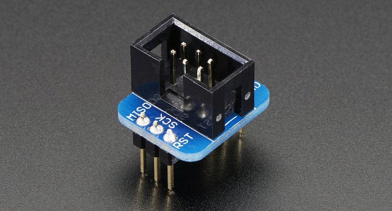
Programming most AVRs requires a six wire interface, with a clock, serial in, serial out, reset, power, and ground. It’s common to include a 3 x 2 pin 0.1 inch header on any AVR-based board. Typically a keyed box header is used to prevent accidental backwards cable attachment, like the header on the Adarfruit breakout board shown above, but sometimes bare 3 x 2 pin 0.1 inch headers are used.
That’s fine for hobbyist work or building a prototype, but when building larger numbers of AVR-based boards, the 3 x 2 pin 0.1 inch header has two significant drawbacks. The first is the component cost and related assembly cost for a header that will only ever be used once, for a few seconds during manufacturing. It’s not a huge cost, but it’s still a factor when trying to minimize the cost per unit – why throw away money? The second drawback is the relatively large physical size of the 3 x 2 pin 0.1 inch connector. For small boards containing mostly surface mounted parts, the ICSP header can complicate layout and routing, or require enlarging the PCB.
Ideally we want a programming connector with these attributes:
- zero per-unit cost
- small footprint, preferably one-sided
- keyed to prevent backwards cable connections
- holds cable firmly attached to the board
Here are some options to consider.
Empty Footprint 0.1 inch
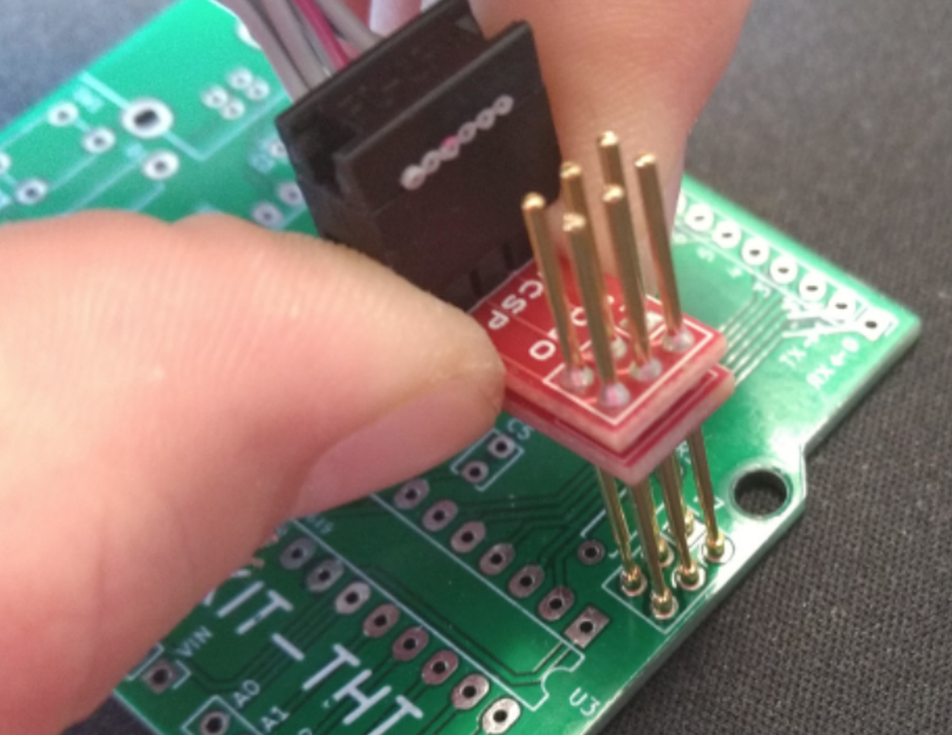
The simplest option is keep the standard 3 x 2 pin 0.1 inch header footprint, but don’t actually solder a header into it. When it’s time to do programming, place a 3 x 2 header in the holes, and apply some sideways finger pressure to ensure the pins make solid contact with the hole plating. It’s low tech, but it works.
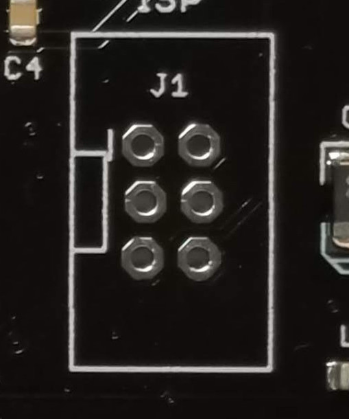
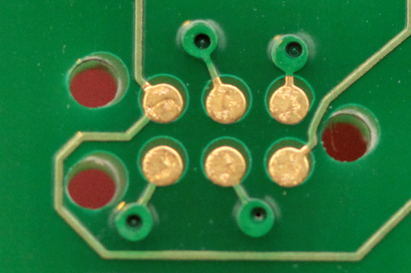
A small optimization is to use a 3 x 2 pin 0.1 inch lock header footprint, where the holes for the individual pins are very slightly offset instead of appearing in a perfect grid. This helps hold the header in place temporarily with friction, so finger pressure normally isn’t needed. It’s what I do for Floppy Emu programming, as shown here:
This approach eliminates the cost of an otherwise-useless programming header, but it’s still too big and doesn’t prevent backwards insertion. And even with the lock header footprint, it’s not great at holding the cable in place for extended periods of development or debugging. The pins often slide out of the holes.
Empty Footprint 0.05 inch
A second option is to use an empty 0.05 inch header footprint, which reduces the required board area to just 25% of original. That’s great, and this might be a good solution. But most AVR programmers have a 0.1 inch cable, so a 0.1 inch to 0.05 inch adapter will need to be built or purchased. That’s a minor drawback, but it only needs to be done once.
0.05 inch pin headers are fairly delicate. Would they hold up to hundreds of insertions and removals, with the added forces of finger pressure or lock headers?
This solution is also not keyed to prevent backwards cable insertion, nor does it grip the cable tightly.
Empty Non-Rectangular Footprint 0.05 inch
If I’m contemplating building a 0.1 inch to 0.05 inch adapter anyway, there’s no reason the 0.05 inch end needs to retain the standard 3 x 2 layout. I could do something with 4 pins in one row and 2 pins in a second row, or any other kind of irregular pin spacing that would prevent backwards cable insertion. Maybe a 7 pin single row design, with one of the pins removed. This would make the footprint area slightly larger than a 3 x 2 layout, but it might be worth it to prevent accidental backwards connections.
Pogo Pins
Any kind of footprint with plated-through holes will hinder routing and component placement on both sides of the board. Spring-loaded pogo pins provide an alternative approach, making it possible to build a one-sided programming interface with exposed pads, similar to this:
With 0.05 inch spaced pogo pins this allows for the smallest footprint of all, but the pogo pins need to be held against the board with one hand during programming, making it awkward to use. It’s OK for a programming operation lasting a few seconds, but not for anything longer.
This simple AVR ICSP pogo pin adapter from Tindie shows one such approach:
It’s nice, but there’s nothing to help align the cable or prevent backwards connections.
For a fancier solution, there are pogo pin cables from Tag-Connect that include alignment pins and optional locking legs to hold the cable firmly on the board:
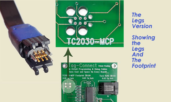
But when you include the area needed for the alignment pin holes, the Tag-Connect footprint is essentially the same area as the standard 3 x 2 pin 0.1 inch header footprint, and the size advantage is lost. And with the version of the Tag-Connect cable that has locking legs, the required footprint area is even larger. Look at this beast:

Conclusion
So what’s the best option? I don’t think any of them is a clear winner – they all have advantages and disadvantages. I really like the idea of pogo pins and exposed PCB pads, but the required alignment pin holes mostly negate the space savings, and I don’t like the idea of always needing one hand to hold the cable in place. For my purposes, I think the non-rectangular footprint with 0.05 inch headers is worth exploring further. I’ll see what I can cobble together for testing.
Read 12 comments and join the conversation12 Comments so far
Leave a reply. For customer support issues, please use the Customer Support link instead of writing comments.
Unless the programming time is long, the one handed option, at least for me, was the best. It\’s actually less irritating than trying to clamp or snap something in and out. So I\’ve been using the tag-connect cables without the latching holes.
What about making pogo pads as on “AVR pogo …” picture to use clip like https://tronixlabs.com.au/news/new-product-eclip-avr-ftdi-programming-fixture-australia/ ?
You can even do such clip as DIY procet with https://www.mill-max.com/new_products/detail/88 + clothespin 🙂
The Tag Connect No-legs variant is my personal preference – they supply a clip that hold the connector in place by clamping from the bottom side of the board, which works well – and the footprint is very small.
For those using the Tag Connect, what is the cable connected to on the other end? From what I can tell, you typically need to remove your programmer’s original cable, rather than attaching the Tag Connect to it somehow. And the process and the connection is different depending on what type of Atmel programmer you have, or if it’s one of the many 3rd-party programmers. For the AVRISP mkII, I believe you need to unscrew the case lid, unsocket the original cable, and attach the Tag Connect cable in its place.
Because I don’t personally do the AVR programming for boards in larger volume production, I need to think about what tools my assembly partner has and whether they’d be willing to mod them to use a Tag Connect cable. It’s not a deal breaker, but if the Tag Connect can function like an extension cord on the existing cable, that might be best.
Also if my math is correct, the size of the Tag Connect no-legs footprint is still nearly the same as the size of the standard 3 x 2 pin 0.1 inch header. Measuring to the center holes, the 3 x 2 pin header is 0.2 x 0.1 inches, and the Tag Connect (including the 3 alignment holes) is 0.2 x 0.08 inches. See http://www.tag-connect.com/Materials/TC2030-IDC-NL.pdf The company ignores the space needed for the alignment holes when advertising “a footprint using about the same PCB space as an 0805 resistor”, which I feel is misleading.
Anyway the cables are cheap enough, maybe I should just get one to try it out.
One solution for 0.1″ JTAG header layouts was to use vias offset by 0.2mm to allow the pins to be temporarily inserted pseudo “press-fit”.
https://twitter.com/bml_khubbard/status/967517385774153730
Although it may require a larger redesign of the PCB, you could use an keyed edge connector. Considering that the GoodFET (http://goodfet.sourceforge.net/) gets away with a male type A USB connector as an edge connector, you could use two (to get the 6 pins for the AVR-ISP connector) USB type A female connectors as a cheap programming adapter. As an added bonus USB connectors are specified for the number of mating cycles, so it should be easy to know how many adapters you will need for a production run.
Here’s another option called “ISP Touch”. It’s a similar idea to the Tag Connect cable, but it’s a DIY solution using a different type of spring-loaded connector I haven’t seen before. I like the idea. The web site where it was first described is now gone, but you can find an archive at https://web.archive.org/web/20180521072347/http://daniel-spilker.com/blog/2011/04/25/isptouch-for-avr-microcontrollers/
I\’m using the Tag Connect on PICs, so I just use an adapter that plugs into my programmer of choice. See https://www.digikey.com/products/en?keywords=AC164110
Can you just make an adapter that lets you plug the existing cable from the programmer into the tag connect cable?
You can use the non-legged Tag-Connect with an adapter that will hold it in place: http://www.tag-connect.com/TC2030-CLIP
I\’m going to try this for the project I\’m currently working on: I bought the 10 pin tag connect with legs and a couple of standard 10 pin headers. I\’m going to build a small breakout board that connects to a standard 10 pin programmer header, but I will use two additional pins that are normally connected to ground to offer TX and RX and have my breakout board also offer an FTDI serial connector. Then I get a single set of pins that has both ISP and serial debug and when detached, a pretty clean finished board.
We\’ll see if the legs end up turning out too large. They do look huge, but I have room in this project.
https://hackaday.com/2019/06/13/soicbite-a-program-debug-connector-for-an-soic-test-clip/
Just came here to post that soicbite project. Smart idea that might be perfect for you.