

Current Limiting Strategies (Again)
I’ve returned to the question of how best to limit the current from Yellowstone’s -12V supply. I discussed this earlier here and here, and had more-or-less settled on the idea of using a current mirror circuit. But now I’m taking a second look at possibly using JFETs or a purpose-designed CCR (constant current regulator) intended for powering LEDs instead.
Here’s a review of why this is needed. Yellowstone has two connectors for disk drives, and each drive is supplied with +5V, +12V, -12V, and GND. Some types of drives don’t actually use the -12V supply, and other types have the -12V supply pin internally connected to the +5V supply pin. Ouch! A picture may help clarify:
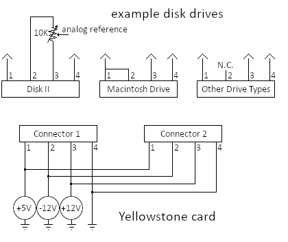
The idea is to insert some new component or circuit inline with pin 2 (the -12V supply pin) of each Yellowstone drive connector to prevent a short circuit when a Macintosh drive is connected. Keeping in mind there might be two Disk IIs connected, or two Mac drives, or one of each, or any combination with other drive types. The anti-short-circuit protection should happen automatically, without requiring any user switch settings or other manual configuration.
Ideally the solution would just disconnect pin 2 when a Macintosh drive is connected, but I don’t know any good way to do that. The next best solution is to limit the current through pin 2, to a level that’s high enough for a Disk II to operate normally, but low enough to prevent problems with the Macintosh drive.
Here are the requirements for the -12V supply connection, as I see them:
- When a Disk II drive is connected, it should see a supply voltage as close to -12.0V as possible, since it uses the supply in an analog reference circuit. This means any resistors between the drive and Yellowstone’s -12V supply should be small, to minimize the voltage drop.
- When a Macintosh drive is connected, the current should be limited to about 10 mA. The exact value isn’t critical, and anything from 5 mA to 20 mA is probably OK.
- The two drive connectors should be isolated from one another, so a Mac drive at connector 1 doesn’t affect the -12V supply for a Disk II drive at connector 2.
- The current limiting function should work automatically, without any control or reset logic.
- Power dissipation in the current limiter should be as low as possible.
- The current limiter should be built from commonly-available parts.
- The current limiter should use the fewest possible number of parts, that are small and inexpensive.
Current Mirror
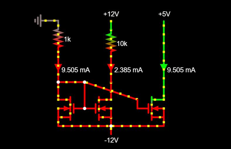
In my last post, I considered using a current mirror. In this circuit, a reference current is passed through a transistor, with two other transistors controlling the -12V supply current, one transistor per drive connector. It can be built with three matched BJTs or FETs, plus a single resistor for setting the current limit.
Here’s an example using FETs, with a Disk II drive plugged into the first connector and a Mac drive plugged into the second. The -12V supply current is shown for each drive connector. The current for the Disk II is nearly identical to the 2.4 mA that would be expected if no current-limiting circuit were present. But the current for the Mac drive is limited to 9.5 mA, instead of the many amps that would otherwise flow due to the short circuit.
A current mirror requires each transistor to have the same voltage threshold, gain, temperature, and other properties, else the current may be incorrect. This is where my difficulties begin. I went looking for a single IC package with 3 FETs, or maybe 4 FETs, in order to help ensure they’d all have matching properties. I learned that these aren’t common: you can find discrete FETs or dual FET packages, but beyond that it’s slim pickings. With the global shortage of semiconductors, I’d prefer not to rely on a part whose availability might be an issue in the future.
I could easily use two dual FET packages, or three discrete FETs, but then their temperatures and other properties might not be well matched. Given that I can tolerate an error of least 2x in the current, maybe this isn’t a big worry. I need to take a closer look at the FET datasheets to get an idea of how much the current might change if one transistor’s threshold voltage is 0.1V off from another’s, or one’s temperature is at 25C and the other is at 85C. Maybe it’s not a big enough issue to worry about for this application.
One small drawback of the current mirror is that it wastes 10 mA from the -12V supply to create the reference current, regardless of whether any of the connected drives actually use the -12V supply.
JFET
Another approach to current limiting is to use a self-biased JFET. A commenter on one of my previous posts mentioned this option, but I never followed up on it. The basic idea is that a JFET is a “default on” device, but its drain-source channel can be partially closed by making the JFET’s gate-to-source voltage negative. The more negative you make Vgs, the further the channel is closed, until reaching the Vgs cutoff threshold where the JFET turns off completely. By adding a resistor at the JFET’s source terminal, and connecting it back to the gate, this behavior can be leveraged to make a current limiter. There’s a nice tutorial about this here.
The JFET’s IDSS (its maximum drain-to-source saturation current) must be larger than the desired current limit. If the circuit can’t reach the current limit, because there’s a large external resistance like in the case of the Disk II drive, the behavior is less obvious to me. From my scrutiny of graphs in the datasheets, it looks like a typical JFET in this situation will behave like a resistor of about 80 ohms, in series with the external resistor used to set the current limit.
Yellowstone would use two independent JFETs for the two disk connectors, with no reference current needed or wasted. That’s nice.
The higher “on” resistance compared to a normal FET is less nice. Combined with the external resistor, it would create a larger voltage drop, so the Disk II drive would see a voltage like -11.7V instead of -12.0V. Maybe that’s still fine. I did a test earlier with a Disk II and a 100 ohm series resistor on the -12V supply, and it seemed to work OK.
It’s slightly complex to calculate what value of external resistor is needed to achieve a desired current limit. The formula depends on the current, the JFET’s IDSS, and its cut-off voltage. The tutorial linked above has the derivation. Or you can eyeball it from the graphs in the datasheet, if a precise value isn’t needed.
I couldn’t find many widely-available dual-JFET packages, which is too bad. So a Yellowstone solution using JFETs would probably be built with two discrete JFETs and two resistors, to make a separate current limiter for each drive connector.
Constant Current Regulators
The JFET sounds intriguing, but then I stumbled across the concept of constant current regulators. From what I can tell, these CCRs are just the JFET plus resistor circuit described above, all wrapped up into a two terminal package that looks like a diode. CCRs are available in different types with different fixed current limits, and are typically used in LED driving applications. As far as I can tell, their behavior is identical to the JFET circuit with the discrete resistor.
Since a CCR is a two-terminal device, it would be very easy to use: just put one in series between the drive and the -12V supply for each drive connector. Boom, done. It’s too easy, I think I must be missing something.
This specific NSI50010YT1G CCR from ON Semiconductor looks nearly perfect, with a built-in current limit of 10 mA. The trouble is that right now it’s unavailable just about anywhere. There’s a 15 mA version in stock at Newark, but that’s still only a single supplier, and I’d rather have 10 mA than 15. I really like the idea of using a CCR, but it’s not going to work unless I can find one with an appropriate current limit, with good availability from multiple suppliers.
Power Dissipation
For any of the above solutions, when a Macintosh drive is connected and the current is limited to about 10 mA, the power dissipation must be considered. With +5V at the Mac drive end and -12V at the Yellowstone end, that’s 17V times 10 mA, or 170 mW of power. Most of the packages that I looked at have power dissipation limits close to that, or slightly higher. I’m uncertain how to optimize this, but probably I need to choose packages that are physically bigger (violating my requirement 7), and/or make the PCB pads very large so they can double as heat sinks. These kinds of power considerations are mostly foreign to me. I don’t want to make the PCB pads any larger than absolutely necessary, since board space is at a premium in the area near the -12V connections. If anyone has recommendations for package types or connection methods that would be better for dissipating a few hundred milliwatts, I’d love to hear them.
And the Winner Is…
I’ll do some more searching for CCR availability. If I can find one with the right properties and that’s widely available, I think that’s my preferred solution.
Otherwise I’ll probably stick with the original plan of using a current mirror and three FETs. I can build it with two dual FET packages plus a single resistor, leaving me with an extra FET available for some future purpose. I’ll do some more analysis and testing to try to estimate how much current error I might see if the reference current FET is in a different package than the FET that limits the current. As long as the answer is closer to 20 percent than 400 percent, it should be OK.
Read 17 comments and join the conversation17 Comments so far
Leave a reply. For customer support issues, please use the Customer Support link instead of writing comments.
Software guy here, with possibly no idea what I’m talking about. Why not use your two dual FETs to make two current mirrors?
“Ideally the solution would just disconnect pin 2 when a Macintosh drive is connected, but I don’t know any good way to do that.”
Just a very naive question: Does the Mac drive has another bridge missing in other drive types, or, equally, does it lack another bridge present in other drive types?
Something like extra ground or supply lines? That would be a very easy way to control a switching component.
Imagine Mac drives had a redundant ground line on pin X not present on other drives. Add a pull resistor to that line, and make that line control a MOSFET switching -12V away from the pinheader. With a Mac drive connected, pin X would be grounded, for any other drive, the pull resistor would mvoe pin X away from ground.
A similar trick could also work with a redundant digital signal on pin X, by pulling pin X to half of the logic supply (with two same-value resistors to GND and logic supply). Logic gates on the Mac (or non-Mac) drive would pull pin X to either GND or logic supply, that can be detected by two comperators and an AND gate. As long as pin X is around half logic supply, a non-Mac drive (or Mac drive) is connected.
====
And yes, Ken is right, you should use independant current mirrors instead of a combined one.
An important advantage of MOSFET-based current mirrors over BJT-based ones is that on the former, an increase in temperature will effectively increase the gate threshold voltage. Since you wouldn’t mind if a MOSFET conducted 100mA if it could somehow avoid overheating while doing so, the natural load-sharing tendencies of MOSFETs should serve you well here.
Yes, two current mirrors with two dual FETs could work. It would trade twice as much wasted reference current in exchange for better accuracy. I need to quantify the likely amount of accuracy error to see if that’s worthwhile.
I haven’t found any way of passively detecting Mac drives based on their other pins. I’m also not sure it would be correct to always shut-off -12V if the drive looks like a Mac drive. There’s also the Apple 3.5 drive to consider, whose interface looks almost exactly like a Mac drive with the exception of the +5V to -12V connection, and that might actually need the -12V supply if a Unidisk 5.25 is daisy chained to it. Apple didn’t make this easy.
For the sake of argument, here’s a specific dual N-channel MOSFET. It’s the Nexperia NX7002AKS. https://assets.nexperia.com/documents/data-sheet/NX7002AKS.pdf
It’s rated for 330 mW max power per device (220 mW per transistor) with a standard PCB footprint, which should be enough, but more headroom would be nice.
For the question of accuracy, obviously this is not my strongest area, but I think it works like this: The gate-to-source voltage Vgs controls how far the conductive source-drain channel is opened, essentially it’s like a voltage-controlled variable resistor. The current mirror circuit sets Vgs equal for the reference and slave transistors, which is intended to open them the same amount, resulting in equal currents through both. Both if the Vgs threshold is slightly different for one transistor, due to process differences or temperature, then the current will be different.
How much different? The datasheet provides some info. First for process variations: The Vgs threshold is listed as 1.6V typical, but can be as low as 1.1 or as high as 2.1 volts. The source-drain resistance Rds(on) can also vary by about 50 percent. Hmmm.
Then the temperature variations. How hot would a transistor get while dissipating 170 mW? Table 6 has some data, but I’m not sure how to read it. The thermal resistance is something like 500 degrees per watt, so that would mean heating 500 * 0.170 = 85 degrees above ambient temperature, putting it at 110C. Ouch. Maybe I should be looking at the “thermal resistance from junction to solder point” rather than “to ambient”, that’s only 115 degrees per watt, which would mean heating about 20 degrees above ambient temperature, to 45C. That would be much better. I’m not at all sure, but let’s split the difference and say my hot transistor would be 80C when the current limiter is active.
Figure 2 seems to show that at 80C the drain current is about 75 percent of the normal drain current at room temperature of 25C.
Figure 11 shows how Rds(on) changes with temperature, it’s about 1.3x as much at 80C than at 25C.
Figure 10 shows how the drain current changes as a function of Vgs, for temperatures of 25C and 150C. This is probably the most useful graph. If Vgs is 2.5V and the temperature is 25C, the current will be 10 mA, right where I want it. But for the same Vgs at 150C, the current will fall to around 7 mA. At 80C we can estimate it’ll be somewhere between those numbers, call it 8.5 mA. That’s a substantial difference but still within an acceptable margin for this purpose.
So what’s the answer? If I make a 10 mA current mirror using this NX7002AKS, with the reference and the slave transistor in separate packages, so they might have process variations or different temperatures, how much might the output current deviate from 10 mA? I’m still not sure. For temperature differences only, figure 10 seems to say the error might be in the range of 15 percent. But for process differences, I think the error might be higher, like 100 percent or more.
Maybe it’s best to build two current mirrors, as was suggested, even though it would waste two reference currents. That would eliminate most of the uncertainty.
Or maybe I should take another look at the JFET solution. No wasted reference currents, but I think the output wouldn’t go quite as close to -12.0V.
I’m spinning my wheels for too long over this question, and need to pick something and move on.
Maybe I picked a bad example. Its junction-to-ambient thermal resistance is listed at 500 degrees/watt, but here’s another dual MOSFET where it’s only 62.5 degrees/watt. https://www.diodes.com/assets/Datasheets/DMN3033LSDQ.pdf That’s a huge difference, and means the package would stay much cooler, and thermal issues would be greatly reduced. I’m not sure what’s behind the difference, maybe the size/type of the physical package.
Okay, I’m definitely talking out of the wrong orifice here, but does it work if you stack the current mirrors up, so the same current flows through the reference side of each? Some actual EE can tell me how little I know about this.
Steve, the FET and resistor constant current source is probably the most flexible, and simplest.
If you wanted to do something more active, you could have your circuit measure the voltage on pin 2 before putting the supply on it. If you measure +5VDC, leave the -12V supply disconnected. If you measure +12V, connect the -12V supply. You could either have your circuit actively measure / switch the -12V, or use a zener to trigger an SCR to connect the -12V power supply. Think SCR Cathode to -12VDC, Gate to zener and series resistor to Anode, Anode to pin 2. Pick a zener that won\’t pass current at 17V (-12V and +5V) but will at 24V (including the 10K pot). When it\’s hooked up to Macintosh drive, the SCR stays off. When it\’s hooked up to a disk II drive, the SCR triggers, and pulls pin 2 down to -12V.
Interesting idea Ken, but from my understanding of the current mirror circuit, I don’t think the reference current can be shared.
Merlin are you referring to the JFET solution, or the MOSFET current mirror, or something else? I took a closer look at using a JFET plus a resistor, and I’m not sure it’s accurate enough for this – which is saying a lot given how much error I’m willing to tolerate. The JFET current source relies on knowing Idss and Vgs(th) to choose the resistor value, but there can be huge variations in those values between one JFET and the next even when they’re supposedly the same type. I looked at one JFET where the resistor value calculated to get 10 mA could actually result in anywhere from 5.6 to 14.3 mA while still being within the min/max bounds of the datasheet values. I also didn’t find many JFET packages that could comfortably handle several hundred milliwatts. But I’m no expert here, and maybe I’m looking at it wrong.
I’ve found another possible solution that I think may tick all the boxes: it’s an LED driver called BCR421: https://www.diodes.com/assets/Datasheets/BCR420UW6-BCR421UW7.pdf I’ve looked at tons of LED drivers, and most weren’t appropriate because they’re high side drivers or because they require some minimum voltage to operate. But the BCR421 is essentially just one variation of the standard BJT current sink design, pre-configured for 10 mA. It’s in a slightly bigger package that can handle more power. And DigiKey has 175000 in stock, so it’s not going to disappear anytime soon. There’s no reference current wasted, and the accuracy should be good since it’s specifically designed for this purpose. I’m still slightly unclear what happens when the set current can’t be maintained (as in the case of the Disk II). I’m going to order a few and experiment with them.
The idea with the SCR and zener is intriguing. I don’t know enough about either component to really say, but wouldn’t that result in the Disk II seeing a supply voltage that’s a diode drop above -12V?
(Once more blocked by the spam filter – grrrr)
First, both NX7002AKS and DMN3033LSDQ are optimized for switching, not for regulating. They can have those tiny cases because they are either isolating with ID close to zero, or fully conducting, with RDS close to zero. Anything in between creates heat that they can’t handle well.
Accuracy is not that important. You just want a current higher than 2.5 mA, but less than 10 or 20 mA to be driven through pin 9. The variable resistor in the non-Mac floppy limits the current that can be driven through pin 9, so your current mirror won’t really mirror the reference current in that case. Only in case of the Mac floppy, it will mirror the reference current, effectively limiting the short-circuit current through pin 9.
Power: It’s just Ohm’s law. The FET is connected between +5V and -12V, so it will see a VDS of 17 V. Assume it perfectly mirrors a reference current of 10 mA, ID will also be 10 mA. RDS will adjust to 17 V / 10 mA = 1.7 kOhm. The power that will be converted to heat is 17 V * 10 mA = 170 mW.
Temperature: The NX7002AKS has a thermal resistance of about 500 K/W to ambient air, so it will heat up to 170 mW * 500 K/W = 85 K above ambient. At room temperature, you exceed the boiling point of water. Put it in a warm computer case of, say, 50 °C and you nearly exceed its abs max rating of 150 °C. In that temperature range, you have to derate the transistor (see fig. 1 and 2), i.e. it can no longer handle the max. IDS without releasing the magic smoke. With large pads connected to the drain pins (fig. 3 mentions 1 cm²), you can get the thermal resistance down to 115 K/W, and so it won’t become that hot.
Wasting a FET for a second reference: That’s exactly what you want. You want an excellent thermal coupling of the two FETs. Having both in the same case is as close as you can get. The trick of most current mirror circuits is thermal changes affect borh (all) transistors and are thus compensated automatically.
Regarding the required voltage at pin 9: You are not sure how much the -12V line is allowed to vary, and neither am I. You should really test it to get a rough idea. Easiest solution: insert a trim pot of about 10 kOhm between controller pin 9 and drive pin 9. Adjust it to short circuit, add a volt meter at floppy pin 9. You should see -12 V to GND. Now increase the resistance until you see, say -6 V. That gives you a real nightmare case, with the offset really misaligned. Try reading from the drive. I would expect it to fail. If not, try several other drives. If none fails, the exact voltage of the -12V line is not very relevant. Reduce resistance to get about -9 V. Now try to find the voltage where all tested drives become reliable again. If unreliable, reduce resistance further. If reliable, increase resistance. You should end with a good guess of the minimal voltage required on the -12V line. Also measure the +12V line, as the relation if the two is what really counts.
Good suggestion about using a pot to see how much the -12V line can vary before problems occur. It still may depend on the particular drive, or even the disk in the drive, but it will provide helpful guidance.
Any thoughts on the BCR421? I think it may be a better solution than a MOSFET current mirror, because it’s specifically designed for a purpose very similar to this. But I need to test it.
After stewing on this for several days, I’ve concluded that any possible current source or current limiter will use one of two general strategies: either there’s a reference current somewhere (to establish the proper gate voltage or base current), or else there’s a sense resistor in series with the load. The current mirror uses a reference current, and thus has wasted current and wasted power. The BCR421 and similar classic designs have a sense resistor in series, which will prevent the -12V supply from ever reaching -12V. From my perspective these are both undesirable, but I need to choose one.
Either type of current source will convert 17 V * 10 mA = 170 mW into heat. If the current setting isn’t very accurate, it could end up being closer to 15 mA and 255 mW. If a current mirror is used, an additional 170 mW will be wasted in the resistor and transistor for the reference current, bringing the worst-case total to 425 mW. If two Mac drives are connected then all these numbers will be doubled, to a worst case of 850 mW heat from a few components in the same area of the PCB. I have no experience in thermal design, but this is starting to sound like a concern. If I need to think about heat sinks, then I’d prefer to find another solution.
With the BCR421, or any other current source that doesn’t involve a reference current, the nominal power will simply be 170 mW per drive connector. The datasheet says the current is accurate to within 10 percent, so that’s 187 mW worst case. With two Mac drives that’s 374 mW, less than half the worst-case power of the current mirror. That seems like a win, so long as its series resistor doesn’t cause the analog reference to go too far out of adjustment.
I did some reading about those datasheet thermal resistance numbers like RΘJA, and I don’t think they’re intended to be used directly for calculating maximum power, but really can only be used for relative comparisons between different IC packages. The RΘJA measurements are made on a particular reference PCB with a specific size, material, with specific traces and copper planes and pads. The same IC on a different PCB or with different size pads could have an entirely different RΘJA. I’m not sure if a real-world Yellowstone card plugged into an Apple II peripheral slot would see RΘJA numbers better than the datasheet or worse. My conclusion is 1) Design very conservatively so I’m nowhere near the maximum power, and 2) Test it in the real world to verify it doesn’t overheat.
This *BEEP* wordpress spam filter drives me insane!
Another way, no current limiters, no current mirrors, but a pull-down resistor that is shorted out when pin 9 is at least slightly negative:
https://www.falstad.com/circuit/circuitjs.html?ctz=CQAgjCAMB0l3BWcMBMcUHYMGZIA4UA2ATmIxAUgoqoQFMBaMMAKACcRC89wNDPuIbGijJ47ATwAswyRT6iCcFgHMQaHgkJUNFYilGQWAJTlhtc4vypUpVMAZtRoCE3IyQpcvHEMg7IEyOhi4sAO5yCApcPB5eRgDOIHiyKIIpBmAK9iAAZgCGADYJdOFmFhngFkYRleZUddlllWk8ldgIjiy5FA69Bgj6-UKZLs6QKGWDBlJWejOyNfP+sjErXRHTFGnLUdZTQ3uRTXYQKFrD2HheCH0QeAA6CWAIT0yvz-Dwb8zQxNxSQGQMjEMCgwFPSBPMBfGxPNDQ2Gw8CQiRSczDKQ+Yb2cQcW4DCwEzgYYIwr5lK43Pro-jEpZY2h9Yn0qbM9mEmxsgyEUnDOJQbkgAVrAVLXQyAZDSWCgDyIDI-A6mQmXmV4EFEUVQk6yVk6qM2A8cnVazsOS5ETWpsEwktchlZt8S3auutuqWayy-C91TK534s349X8cyWIaDVVofoiIa0OnwFBj6gunR4ujTmvUiczEsWLAADkJrvIlSXCCgvBB7VTS8XqRt65xK03CBclrW22WvGLKSWBcTe0A
This is using ideal components and may need some real-world improvements, but it shows the idea pretty well.
Start with the switch opened for a Disk II. Voltage at pin 9 is initially slightly below 0 V, that makes the comperator switch the FET and bridge out the lower resistor. That sets pin 9 to nearly -12 V. The simulation shows -11.988 V. Current is limited by the upper resistor and RDSON of the FET (less than 1 Ohm) in parallel to the lower resistor to about 2.4 mA. No hot semiconductors thanks to the upper resistor.
Start with the switch closed for a Mac drive. Voltage at pin 9 is initially +12V and stays there, the comperator keeps the FET off, the short-circuit current flows through the lower resistor and is limited to about 3 mA. No hot semiconductors thanks to the lower resistor.
Connecting no drive or one of the other drive types where pin 9 is unused does not matter at all. The upper resistor is infinite, the switch is open, so the positive input of the comperator is pulled down to -12 V by the lower resistor and the FET is switched on. No significant current will flow, as pin 9 is open. No hot semiconductors.
In the simulation, changing the switch from open to short just works. In the real world, it will probably kill the FET, as it is connected across 24 V while switched on. So this circuit is not able to handle hot-plugging of a Mac drive.
In the simulation, changing the switch from short to open just works. That should also work in the real world. Current is initially limited by the lower resistor, until the voltage at pin 9 becomes negative, and the FET switches on. This should allow charging the capacitors in the Disk II, which initially present a short-circuit.
Improvements:
Maybe the inverting input of the comperator should be a little bit negative, e.g. by connecting it via an 1N4148 to GND and a pull-down to -12 V, that gives about -0.5 to -0.7 V. The exact voltage does not matter.
Some comperators have an open collector / open drain output, in that case, a pull-up resistor from comperator output to GND is needed.
Maybe a capacitor is needed between GND and the positive input of the comperator to eleminate HF noise.
The lower resistor may need to be adjusted. It has to be smaller than the upper resistor to pull pin 9 below 0 V. The larger the lower resistor, the lower the short-circuit current for a Mac drive. Unfortunately, it also forms an R-C circuit with the capacitors in the Disk II, limiting how fast pin 9 goes below 0 V. So for fast startup, the lower resistor should be as small as possible. Which increases short-circuit current and heat in case a Mac drive is connected.
Oops, the MAC floppy does not short pin 9 to +12V, but to +5V. Easy to fix, here is a new simulation that also allows “other” drives that leave pin 9 open.
https://www.falstad.com/circuit/circuitjs.html?ctz=CQAgjCAMB0l3BWcMBMcUHYMGZIA4UA2ATmIxAUgoqoQFMBaMMAKACcRC88QAWbFJ24UMhKCAJwWAcxBoeCQlXkVigqpBYAlITzBLdIYmI18qYdeJgJthjJF6G8cK2ZBNLG6DYDuhhKJ2DlAsAM4SAnLCeJFggeYgAGYAhgA2oXQsfjGCKNGR2AjqLIkUFmWCCGoVILHeULAoWaqCvMYtfJGaflWtkVw8-MU91UUKo-HNvSJiAzMhvJAQKIo12HiOCOUQeAA6oWAI+0xHB-Dwx8zQpDe3d3uhkPtg5xr7aM+vr+D7mhy8+hqvGcNXM8HYNUUtHKhAwlhe52a6025QBYi2wz4IIxkPK3VxlXKUJCPRhcJq9kc+JxlKCVOaKiGHSZmgA8kZAoVBC8UI4ueASRyxPycrUiiFsPZDPy5osEhpmrL+sI5YLRTLhPz8SsxG0xPoqHrBQa+O0TcT8eaDCoLQzVmM5PgKHlBTaXYyuiwAA61DbzZGcXkChV+AMBYV+nH4gOEIMx1bRv2EVYB2mJxy0mnBTQ6UUm0XtUyLaimawQuZxWbCXmmBFScJzbDYKs8TDwpJpDKKzXN6Xi-FzNuGGuCiuBCsGfF5wJ5ycsIA
With both switches open, it simulates an “other” drive that leaves pin 9 open, no current flows, pin 9 is at -12V.
With only the left switch closed, it simulates a Disk II drive, 2.399 mA through the FET, pin 9 at -11.988 V.
With only the right switch closed, it simulates a Mac drive, and due to the lower positive voltage of only 5 V, the current through the lower resistor is just 2.074 mA, total power 35.258 mW, all through the resistor.
Thanks, that’s a clever circuit! There’s very little waste power anywhere, which is great. I have minimal experience with comparators or op-amps (which I think is basically what this is?) so I don’t know what problems might arise. As a latching circuit, I would think the concerns would be false triggering due to transient noise, or improper behavior due to start up sequencing. Maybe the power supplies don’t all turn on at the same time or at the same rate? Maybe there’s a danger when the supplies first turn on and are all near 0 volts? What are the power supplies for the comparator?
I’ve just taken some measurements that suggest this whole line of investigation may be irrelevant, and a simple series resistor will work. I was very surprised that even with a large series resistor, such that the Disk II drive sees a voltage around -6V instead of -12V, reading and writing of disks still appears to work. I increased the resistor value as high as 4.7K, and three of my four test disks still worked, but Oregon Trail failed to boot. But then when I removed the resistor and restored a normal -12V supply, Oregon Trail still failed to boot. That disk had been working a few minutes earlier, and I didn’t write anything to the disk, so I’m not sure what might have happened to it. I need to solve this mystery and make sure I didn’t somehow damage the disk or the drive, but maybe I can simply put a 1.8K resistor in series with the -12V supply instead of worrying about all these current limiter and supply switching circuits.
Tux2000, sorry you keep running into the spam filter. Send me a private email if you’d like to investigate why. It may also be possible to whitelist you if you create an account on the blog and use it for posting.
I recopied my Oregon Trail disk and booted successfully ten times with a 4.7K series resistor installed on the -12V supply, which resulted in a measured voltage for the Disk II of about -5.0V.
Then I tried a 10K resistor, resulting in a -12V supply of -0.78V. Worked 10 times.
33K resistor, +3.7V: Worked 10 times, but it seemed to boot more slowly than before.
100K resistor, +6.85V: Did not boot.
Wow, that was surprising. If these results are to be believed, it seems that the value of the “-12 volts” supply hardly matters at all for the Disk II. I’m not sure what to make of this.
Spam filter: Thanks, just a little bit annoyning, effectively limits me to one or two posts per day, solved captcha does NOT accept my posts. Oh well …
Comperator supply: -/+ 12V to be sure, not all comperators accept voltages outside their supply range. Theoretically, GND to positive supply and -12V to negative supply should be sufficient.
Comperator switch level: That’s why I suggested the extra diode, it move the switch level a little bit away from 0 V.
Startup behaviour is really the only problematic thing in my circuit. Virtual MOSFETs don’t release magic smoke. 😉 There is only one thing that must not happen: The MOSFET must never switch on when pin 9 is connected to +5V (Mac floppy). I’ve played a little bit with the simulator, but in the end, all that is needed is a little delay before the MOSFET switches on, just enough for the power supply to stabilize. I suppose there is no POWERGOOD line on the Apple PSU? Very likely, a small capacitor (1 µF?) from gate to source is suffient, in combination with the resistor from the comperator to the gate. It shorts out the comperator output, keeps the gate close to source level and the MOSFET switched off.
There is only one way to be sure: Build a prototype, connect pin 9 to +5V (perhaps via 10 Ohm to protoect the Apple), supply the prototype from the Apple, and expect a few burned MOSFETs until you get the right power-up behaviour.
Comperator vs. Op-Amp: Yes, very similar, comperators are designed for “insane” gain, so much that their output is always either fully positive or fully negative even at tiny input differences. You can’t really use them as amplifiers. Mathematically, they implement the sign function. Some comperators have only an open collector / open drain output, lacking the push/pull output of an op-amp. That allows to connect their outputs in parallel.
Pin 9 inline resistors: Very impressive. I expected problematic behaviour starting at around 75% of the nominal voltage (i.e. -9V). The Disk II seems to be extremely well designed, with a lot of headroom for component tolerances. Perhaps that’s the reason why the Disk II needs -12V at all. Your tests suggests that connecting the potentiometer to GND should have been sufficient for most cases. The read amplifier data sheet also does not need a negative supply. But using the -12V line that probably is also used for other things in the Apple, and thus is already there at no extra cost, allows to adjust worst-case read-amplifiers way beyond what the datasheet design allows.