

The Yellowstone Tester
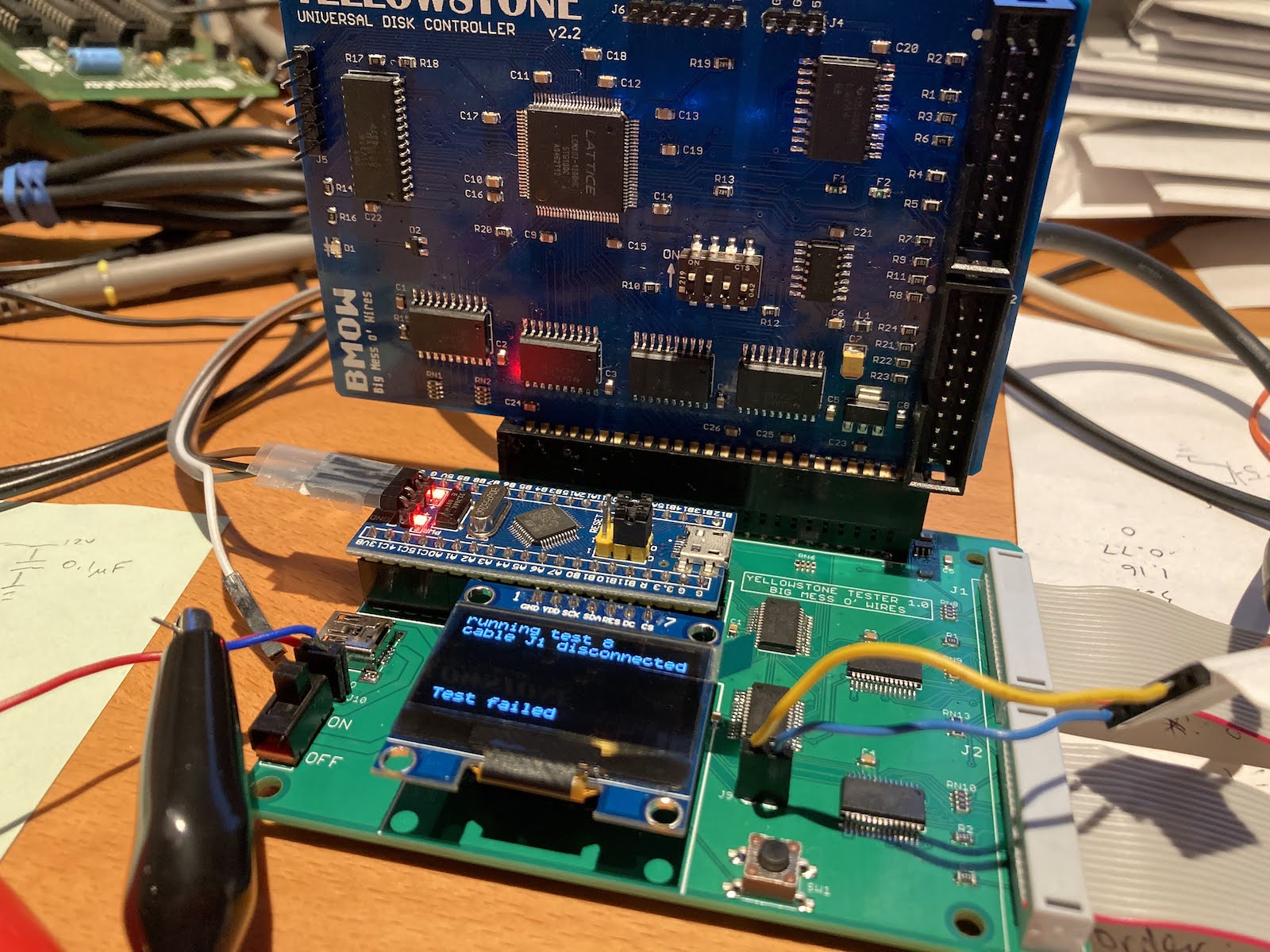
I once said I’d spend a maximum of one day on development of an automated tester for the Yellowstone disk controller. Haha, that was so cute. Today marks two months since I began work on the tester. Today was also the first try with the final (I hope) tester hardware. So far it seems to work, mostly.
Yellowstone is an FPGA-based disk controller for Apple II computers. It’s complex enough that fully testing each board is a non-trivial task. Manually testing a large batch of boards would be out of the question, so an automated tester is needed. The heart of the tester design is an STM32 “Blue Pill” board, combined with four Microchip port expander chips to reach a total of 80 I/Os. There are also a few analog sensors for measuring current and voltage, as well as a current switch IC that will disconnect the board being tested if it draws too much current.
Unexplained Current Changes
The ability to measure the supply current was one of the key features of the tester design. Unfortunately it doesn’t seem to work as well as I’d hoped. I was convinced that I needed to measure the combined supply current of the board being tested and the tester itself, in order to capture all possible paths where a short circuit might occur, and that works. So far, so good.
The odd thing is there are unexplained fluctuations in the measured current. With no Yellowstone board present, the current sensor reports about 26 mA used by the tester itself. But if I write some code that sits in a loop repeatedly measuring the current, but doing nothing else, sometimes the current briefly jumps up to 35 or 40 mA. This happens roughly once every second, but not consistently enough to make a reliable pattern. With a Yellowstone board present, the current is higher but similar current measurement fluctuations are still happening. At first I thought this was some deficiency in the STM32 ADC, but other analog measurements by the STM32 don’t have the same issue.
I’m not sure if these current changes are real, perhaps caused by some internal activity of the STM32 briefly increasing the supply current, or if the changes are somehow an artifact of how I’m measuring. Either way, the fluctuations are large enough to undermine most of what I’d planned to use the current measurements for. A measure of 70 mA +/- 25 mA isn’t accurate enough for much diagnosis beyond detecting a hard short-circuit.
Unresponsive ICs
A second problem I encountered is that the Microchip port expander ICs occasionally don’t respond to SPI commands. This often happens when I first turn on the tester after it’s been off for several minutes, but never happens when turning it briefly off and on, or resetting the tester while keeping the power on.
Surprisingly (or maybe it’s not surprising) there seems to be a relationship between the current fluctuations and the unresponsive port expanders. After the board has been off for several minutes, and is then turned on, I’ll very often see an immediate current fluctuation followed by unresponsive port expanders. I’ve added some code when the tester starts up that will repeatedly poll the port expanders until they respond as expected, and this appears to be working for now.
The tester PCB isn’t well designed for probing internal signals to see what’s wrong. Because I already built a breadboard prototype of the tester previously, and thought it was working, this new PCB was designed for small size rather than for debugging. It may require some fancy soldering and old-fashioned detective work to figure out what’s happening here.
Read 6 comments and join the conversation6 Comments so far
Leave a reply. For customer support issues, please use the Customer Support link instead of writing comments.
Is it possible to re-route the power lines so that the current sensor only measures current supplied to the DUT, rather than total current? Or would that not work when detecting a short?
It’s definitely possible with a PCB revision, but I’m not sure whether it would help. If the current fluctuations are real variations from the STM32 and not some measurement phantom, then it would bypass those. But it would also make it impossible to detect some types of short circuits through current measurements. They could still be detected (hopefully) through functional test failures, but I like the idea of watching the supply current as the tests progress as a second way of detecting problems.
Maybe I’ll try to rig up something with the oscilloscope to get a moment-by-moment supply current measurement, and see if shows the same fluctuations I’m measuring with the current sensor.
I tried using two probes on my oscilloscope in Math – subtract mode to measure the voltage across a 1 ohm low-side resistor. So the measured voltage in mV should be the same as the supply current in mA. I got an average value around 8-9 mA, which sure seems wrong, since three other measures all showed numbers around 25 mA. Maybe there’s a small constant offset between my two scope probes? It looks like the resolution of the measurement is 4 mV so the graph looks very quantized. So maybe I can’t measure the absolute current this way, but hopefully it’s still valid for watching changes in current.
Using the scope, I see regular spikes roughly every 16 microseconds. This is a frequency of 62.5 kHz, or about twice the frequency of typical 32.768 RTC clock crystal. It’s probably creating a current spike on every edge of the RTC signal. These spikes jump up to 50 mA or higher, but only for about 100 ns. I think an ADC measurement spans several microseconds, so it may partially smooth these out. There may also be a lower-frequency repeating pattern in the supply current, on the order of 1 second, but the noise from the 16 us pattern swamped it so it’s hard to see. I need better scope skills – maybe there’s a way to low-pass filter the Math – substract signal, or use a differential probe or something. I tried using the FFT function on one of the two probes, but I couldn’t make it display anything at all, and I’m surely doing it wrong.
I don’t know why any of this would be related to non-responsive port expanders. Maybe that was just a coincidence.
With a bit more sleuthing, I see that the lower-frequency repeating pattern happens every 9.7 milliseconds and shows a 50 percent supply current increase lasting for a period of 868 microseconds. That’s in addition to the every 16 us pattern from the RTC. All of this is happening while the STM32 is doing “nothing” except repeatedly measuring the current. I’m not sure what any of this means, but at least it’s hard data.
What’s the ADC sample rate? From looking at data sheets for other microcontrollers, I remember that ADC’s tend to be “power hungry” and might be generating the spikes when they sample or convert. Also, if an internal voltage reference is used for the ADC, it could be “pumping” that reference voltage.
I’ve modified the tester code to make a series of ADC readings over a 1.2 ms period, and then take the minimum result. Since the mystery current increases are shorter than this, it works as a simple filter and now I get consistent digital current measurements with a variance of about 1 or 2 mA. That’s good enough for my needs.