

Circuit Sleuthing: Unidisk 5.25 Enable and PHI1

While chasing down some Yellowstone hardware bugs, I discovered an unexpected analog-type behavior on the enable input of the Unidisk 5.25 (A9M0104). This is an active low digital input that’s used to enable or disable the disk drive. Under the right conditions, something inside the drive itself is creating a substantial load on this input signal, or actively driving the signal. So instead of a nice clean 0 to 1 transition, I see stuff like the graph shown above. When the intended enable output from Yellowstone switches from low to high, the actual signal climbs from 0V to about 3.3V (on a 5V system) for about 50 microseconds, then quickly drops to 1.2V, then starts slowly rising. Then about 250 microseconds later when the PHI1 input switches from high to low, the enable signal crashes to 0V before quickly recovering to 2.9V, and eventually reaching 3.3V again. This causes buggy behavior and errors. Hmmm.
This problem only happens when PHI1 is high at the time when the enable signal is de-asserted. If PHI1 is low, the the enable signal follows a clean transition from 0 to 3.3V:

If PHI1 is high, but remains high forever instead of transitioning like the first example, then there’s still trouble with the enable signal, but the crash to 0V doesn’t happen:

The Unidisk 5.25 isn’t a very common drive, and many Apple II collectors have never heard of it. For comparison, here’s a repeat of the first example with a common Disk II drive instead of the Unidisk 5.25. There’s something strange, but it’s not as severe, and the crash to 0V doesn’t happen:

That’s all the evidence. Now let’s look at some schematics to try and determine what’s going on here.
Schematics Research
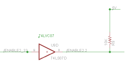
Yellowstone has two independent disk connectors. This weirdness with the enable signal only happens when the drive is connected to Yellowstone’s J2, which uses a different method than J1 to create the enable output. For J1, the enable signal is actively driven high or low by a 74LS244. But for J2, the enable signal is actively pulled low by a 74LVC07, and passively pulled high by a 10K pull-up resistor to +5V:
This creates a weak enable high signal for J2, which is certainly part of the problem here. But before saying “you shouldn’t do it that way”, I’d like to understand why this doesn’t work here, and what exactly is going wrong.
The first oddity is that even when the system’s at rest, the enable voltage is about 3.3V rather than the expected value around 5V. Since the high signal comes from the 10K pull-up resistor, the voltage should theoretically be about 5V as long as nothing in the drive is consuming more than a tiny amount of current from the enable signal. So it seems something in the drive *is* consuming appreciable current from the signal, or is otherwise influencing the signal voltage.
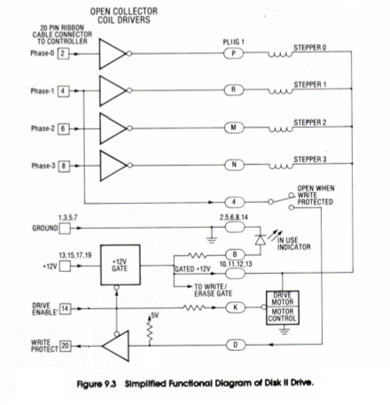
The second oddity is PHI1’s influence. What does PHI1 have to do with anything, and why should it affect the enable voltage? The PHI0 to PHI3 inputs are normally used to control the stepper motor for switching between tracks on the disk. But the PHI1 signal also has a second purpose related to the write-protect detection circuit:
You can confirm this by checking the schematic for the Disk II analog board, although the write-protect switch itself isn’t shown:
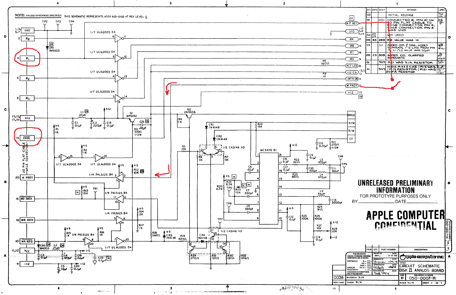
(click the image for a hi-res version) PHI1 is routed through the write-protect switch and becomes the value for the WPROT output, and is also used to gate the WRREQ input and prevent writing to write-protected disks. This explains why PHI1 is different from PHI0, PHI2, and PHI3, but not how it might affect the ENABLE input signal’s voltage.
That’s the Disk II. What about the Unidisk 5.25? It should be very similar, but unfortunately I can’t find any reliable schematic of the Unidisk 5.25 analog board. There’s this Unidisk 5.25 schematic, but I’m not sure it’s what it claims to be. It shows a drive with two 25-pin connectors, but the Unidisk 5.25 only has a single 19-pin connector. There’s also this Unidisk 5.25 PCB image, but it also shows two 25-pin connectors. I think both of these may actually be for the Duodisk, or for some never-released prototype, rather than for the A9M0104 Unidisk 5.25. So we’re forced to guess about what’s inside the Unidisk 5.25, with the knowledge that it’s mostly the same as the Disk II except with a half-height drive instead of full height.
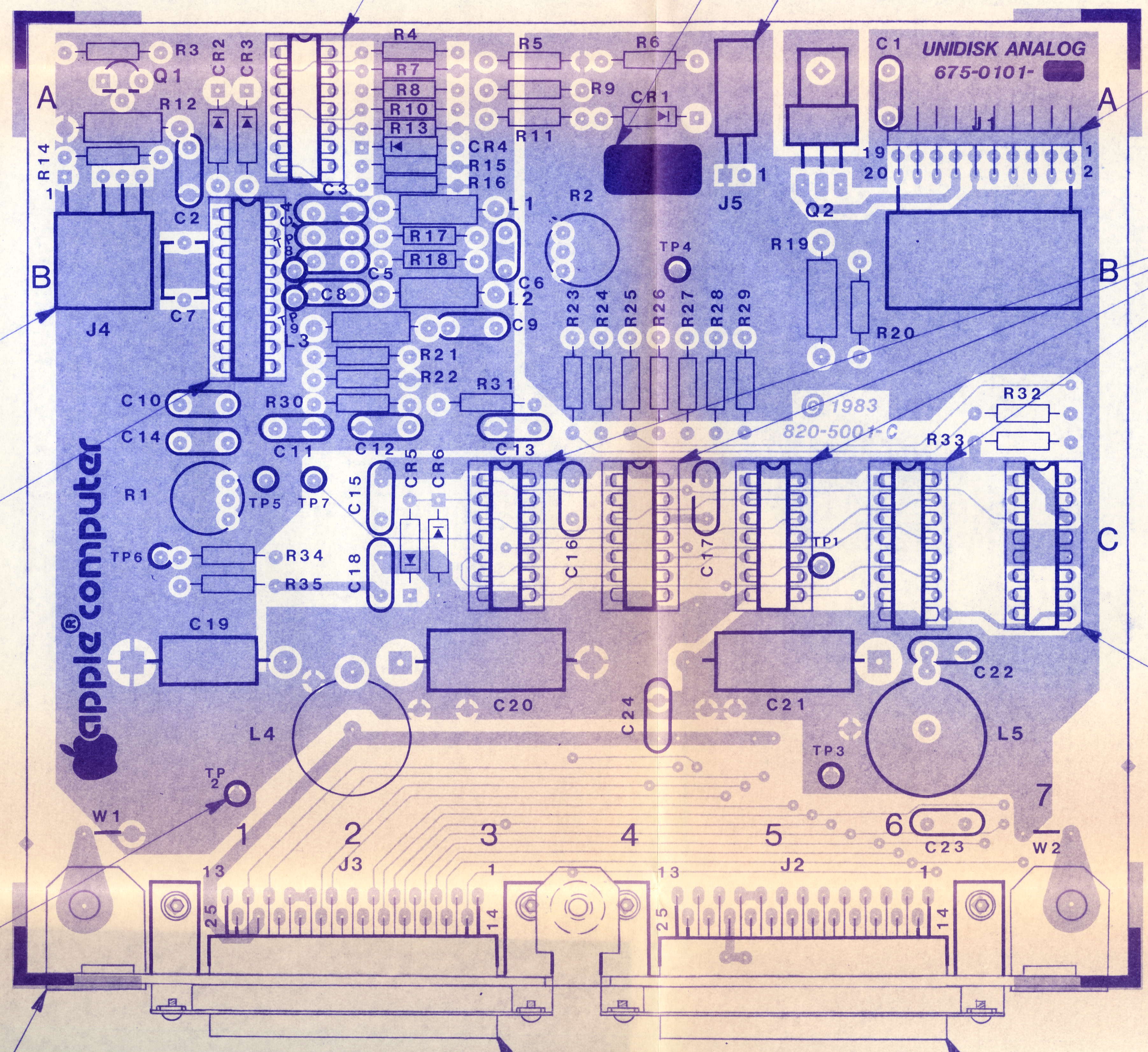
A few things on the Disk II analog board schematic are noteworthy. The ENBL input has a 1K pull-up resistor to +5V (R1), so the 10K pull-up on Yellowstone isn’t relevant or necessary for this particular drive. ENBL is connected to three digital inputs. Two are 74LS inputs with input current about 0.1 mA, and the third is some type of inverter/transistor array with an input current around 1 mA. That’s a fairly large amount of input current. If my math is right, 1.2 mA though the 1K pull-up resistor R1 would drop 5V down to 3.8V, which is at least in the general neighborhood of the 3.3V that I measured.
ENBL is also connected through a 1K series resistor R9 to something called -MTRON. That’s not shown, probably because it’s part of the Shugart drive mechanism and not the analog board. What’s there? Given the series resistor and the fact that ENBL is active low, I’m guessing maybe there’s a PNP transistor at -MTRON? What else is there? Could this be the source of all the strangeness?
When the write-protect switch is closed, PHI1 will have an extra 10K pull-up to 5V at R12. It will also be connected to a couple of 74L125 inputs. But I don’t see any capacitors or other interesting details on the PHI1 circuit path that might explain what’s happening. Except for the power supplies, I don’t see any inductors or capacitors anywhere that look like they might cause the weird behavior I’ve observed.
Could the +5V supply inside the Unidisk 5.25 be changing? It’s isolated from the external +5V input by an inductor, so it’s possible. And resistor R1 would cause any large change on the internal +5V to influence the ENBL voltage too.
It’s worth mentioning that the Unidisk 5.25 is known to have something strange about its write-protect circuit behavior, and the drive isn’t compatible with the Apple IIgs ROM 03. But I’ve never found any definitive explanation for just what it is about the Unidisk 5.25 that’s different. I discussed this in another blog post from a few years ago, but in a different context, and my information about the Unidisk 5.25 was mostly speculation:
There’s also a Unidisk 5.25 analog board Twitter thread in which another Apple II hacker pondered some of the same questions about the write-protect circuit, but I don’t think he ever found answers.
According to some Yellowstone beta testers, the Disk IIc A2M4050 also has similar problems when it’s connected to Yellowstone’s J2. I don’t have a Disk IIc, so I can’t confirm if it’s the same enable voltage problem as the Unidisk 5.25, but I’d bet it is.
Solutions?
Without knowing exactly why the Unidisk 5.25 behaves this way at Yellowstone’s J2, I can still see a few potential solutions.
The easier solution is to make the enable signal’s pull-up stronger, so it more closely approximates an actively-driven signal’s logical high output. I was able to test this by paralleling an additional resistor with Yellowstone’s pull-up. I tried successively smaller and smaller pull-up resistor values (stronger pull-ups), and the enable signal gradually improved, and the “crash to 0V” became a crash to 0.5V, then 1.0V, etc. With 470 ohms in parallel with the original 10K ohms, the low point of the crash was improved to 2.0V and the drive began working normally. This solution acknowledges that something unexplained is pulling ENBL low, so it compensates by pulling ENBL high more strongly. But it doesn’t actually explain the problem, and it means about 12 mA would be wasted in Yellowstone’s 74LVC07 whenever J2’s enable is driven low.
The better solution is probably to redesign the Yellowstone PCB, so J2’s enable can be actively driven high and low, instead of using the ’07 and a pull-up resistor. Then J2’s enable circuit would match J1’s. I didn’t do this initially because I ran out of buffer pins, and didn’t want to add another chip just for this one signal. Even now, when I consider the prospect of revving the PCB yet again, and going through another round of verification and beta testing, I feel sick.
A possible third solution might be to leave the hardware as-is, and solve the problem in firmware. Since I’ve characterized the problem and when it happens, maybe I can tweak the firmware to avoid it. For example, maybe I can ensure PHI1 is always low before J2’s enable is de-asserted, or else insert a few milliseconds of blanking time whenever J2’s enable is de-asserted, to ensure nothing else happens while the enable signal voltage is acting strangely. But any firmware solution would be more like a bandage than a true fix, so it’s probably better to identify and fix the root cause.
Read 5 comments and join the conversation5 Comments so far
Leave a reply. For customer support issues, please use the Customer Support link instead of writing comments.
I took some photos of the Unidisk 5.25 analog board. https://photos.app.goo.gl/aCHwGKjtB6KxDhKP7 From a high level it looks very similar to the Disk II analog. It uses a HA1127 transistor array IC, while the Disk II uses a CA3146 transistor array IC – that’s the only difference I’ve noticed so far.
Some random thoughts:
Does the same thing happen with another drive (same model) or only with this particular drive?
The ULN2003 is NOT a digital circuit, despite being drawn as an inverter. It is just seven darlingtons circuits, each composed of two NPNs, three resistors, a suppression diode, and two parasitic diodes. See the datasheet from ST (https://www.st.com/resource/en/datasheet/uln2001.pdf). For a proper TTL inverter, it lacks the typical emitter input circuit of a TTL device (see https://de.wikipedia.org/wiki/Datei:7400_Circuit.svg). Given proper logic levels at the input, the high amplification of the darlington circuit will cause digital behaviour most of the times. But if the base (input) current is low enough, the darlington will not be saturated and show analog behaviour.
Ground lift: From previous posts, we learned that Apple II slots have only a single GND pin, and thus Apple II cards may experience ground lifts. I would measure the voltage differences between Apple II power supply GND and Yellowstone GND, and between Yellowstone GND and Floppy GND, preferably using an oscilloscope (mV range, bandwidth limited to 20 MHz or less). Make sure that Apple GND, Floppy GND, and oscilloscope GND are isolated from each other. If you have, use a battery-powered scope. If not, supply the Apple including its monitor and the floppy from an isolation transformer to make sure their GND is not connected to PE. Mains powered scope GND is always at PE, and must stay at PE. You want the isolation to avoid an extra ground loop through the scope.
Suppy voltages: If you suspect that the 5V rail does funny things in the floppy drive, measure it, again using an oscilloscope, again with isolated GND as above. You will probably see more details when using AC coupling and one of the mV ranges. While your at it, also measure the other supplies.
Invisible capacitors: There is a bunch of non-obvious, small capacitors in the circuit between the Yellowstone and the floppy drive. All of the signal lines are bundled in the drive cable, doing capacitive and inductive coupling between each other. It’s hard to see from the analog board pictures, but it seems the cable has a common, grounded shield. That adds extra capacitive coupling to GND.
None of the Disk II Analog Board inputs is a Schmitt-Trigger. Phi0 to Phi3 and -Enable are ULN2003 darlingtons with possible analog behaviour, WR_DATA and -WR_REQ are standard 74LS125 inputs. Assuming the Unidisk has a similar input, I would expect push-pull-outputs on the other end of the cable. 74(LS)XX TTLs are always a little bit weak when driving high compared to driving low, that probably explains the extra pull-ups R1, R12, R15, and R16 in the Disk II.
If you look at the output stage of a typical 74XX TTL IC (see again https://de.wikipedia.org/wiki/Datei:7400_Circuit.svg, or e.g. the 74LS125 datasheet), you’ll notice that the high-side transistor has a collector resistor of about 100 ohms. That’s why TTL ICs can source much less current than they can sink.
You could try reducing the pull-up in the Yellowstone (R9) to 1k or less, thereby driving the ENABLE high level closer to +5V. The TI SN74LVC07A can sink 24 mA above a VCC of 3 V, that’s equivalent to a total pull-up of about 200 ohm (including the pull-ups in the floppy) at 5 V.
Thank you for the very detailed reply! Yes, the same thing happens with other drives (same model and similar models) as reported by testers. Nobody else has repeated my voltage measurements, but the reported failure behavior is the same.
That’s great information about the ULN2003. Low base current could certainly be part of the problem.
I think you’re right that changing R9 to a smaller value should fix this. In some limited tests that I tried, it seemed to work OK. But after reflecting on this for a few days, I decided the best answer is to redesign the circuit to use a push-pull driver for ENABLE at J2. That’s how it’s really intended to work. But rather than delay Yellowstone’s release for this, I’m going to roll the change into the next hardware revision and add a compatibility note about this drive to the manual for the current board revision.
I have 2 Disk OOcs and can confirm the Disk IIc is pretty much the same as the internal drive. So if you have a IIc to open up and peek at, you can see basically what a Disk IIc looks like. The only differences are that the activity LED is not hooked up directly to the internal drive, and it obviously doesn’t have a DB19 cable. But the analog board and everything else is the same. Like the Unidisk 5.25, it also uses the HA1127P IC. I’d be happy to open one up, take pics, and even do some continuity tests on it if there are any points of interest if you need it.
Good to know! I will remove the internal drive from my IIc and try it with Yellowstone. I tested that briefly much earlier, but not in the particular configuration that’s causing trouble here.