

A Tale of Three Bidirectional Level Shifters
Level shifters, voltage translators: whatever you call them, these devices are very handy when interfacing 5V and 3.3V logic for devices that aren’t 5V-tolerant. The 74LVC244 has long been my go-to solution for unidirectional 5V to 3.3V level shifting, and for 3.3V to 5V I’ll typically do nothing, since the 5V inputs generally work OK without shifting. But sometimes you need bidirectional level shifting with automatic direction sensing, and you may also want to step up those 3.3V signals to a full 5V. Enter three solutions from Texas Instruments: TXB0104, TXS0104, and TXS0108. These three chips all provide 4 or 8 channels of bidirectional level shifting with auto direction sensing, and at first glance they all seem very similar. But as I recently discovered, under the hood you’ll find significant differences in how they work and the types of applications they’re best suited for.
TXB0104
TI describes this chip as a “4-Bit Bidirectional Voltage-Level Translator With Automatic Direction Sensing.”
This TXB0104 4-bit noninverting translator uses two separate configurable power-supply rails. The A port is designed to track VCCA. VCCA accepts any supply voltage from 1.2 V to 3.6 V. The B port is designed to track VCCB. VCCB accepts any supply voltage from 1.65 V to 5.5 V. This allows for universal low-voltage bidirectional translation between any of the 1.2-V, 1.5-V, 1.8-V, 2.5-V, 3.3-V, and 5-V voltage nodes. VCCA must not exceed VCCB.
Power VCCA with 3.3V, power VCCB with 5V, and then it just works without any further configuration. Signals on pins A1..4 are propagated to pins B1..4 and vice-versa, while performing level shifting. But how? Scroll down to page 16 of the datasheet to find this block diagram of a single level shifter channel:
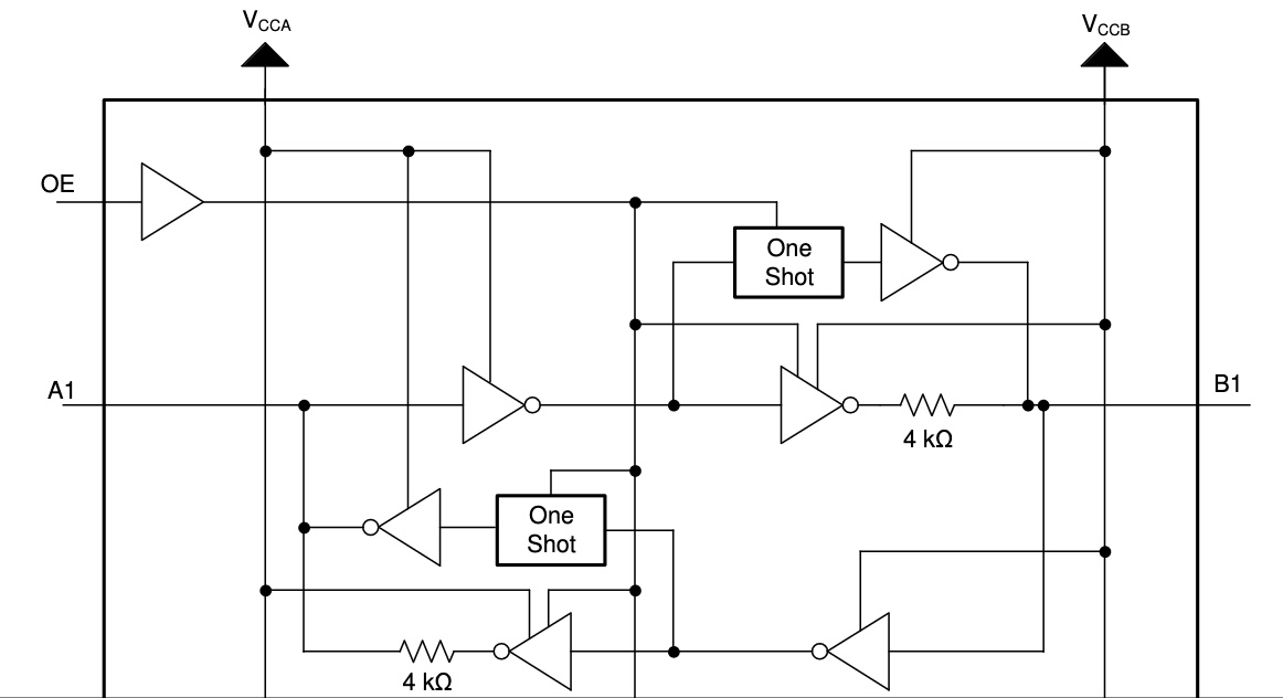
It’s complicated, but the most important thing here is that when the pins are treated as outputs, they’re actively driven to a high or low voltage with a pair of inverters. The output drive current is supplied by the TXB0104, through these inverters. When the pins are treated as inputs, the input signal is supplied to another inverter. In many ways it’s like the 74LVC245 except the direction is sensed automatically.
Elsewhere in the datasheet, it mentions a maximum data rate of 100 Mbps when VCCA is at least 2.5 volts.
TXS0104
Change a single letter in the part name, and you get TXS0104. What’s different? TI describes it as a “4-Bit Bidirectional Voltage-Level Translator for Open-Drain and Push-Pull Applications”. That sounds awfully similar to the TXB.
This 4-bit non-inverting translator uses two separate configurable power-supply rails. The A port is designed to track VCCA. VCCA accepts any supply voltage from 1.65 V to 3.6 V. VCCA must be less than or equal to VCCB. The B port is designed to track VCCB. VCCB accepts any supply voltage from 2.3 V to 5.5 V. This allows for low-voltage bidirectional translation between any of the 1.8-V, 2.5-V, 3.3-V, and 5-V voltage nodes.
That’s virtually identical to the text in the TXB datasheet. But the block diagram of a single level shifter channel reveals something that’s completely different!
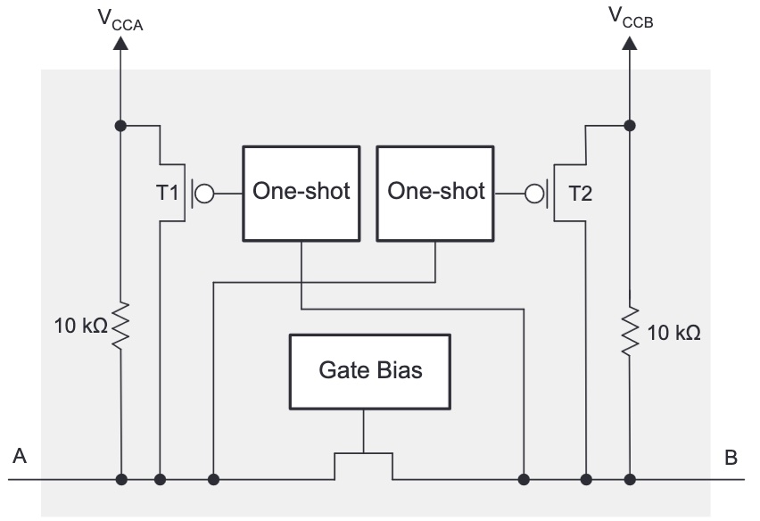
The chip uses a pass transistor to connect the A and B pins. It’s the same basic concept as the classic single-transistor level shifter, commonly built with a BSS138 MOSFET, whose theory of operation is described in section 2.3.1 of this Philips application note. The drive current for low signals is supplied by the external device that’s driving the pin, and not by the TXS0104. For high signals, there’s a 10K pull-up resistor. The TXS0104 improves on the classic design by adding one-shots that can accelerate rising edge times compared to what’s possible with the pull-up alone.
This type of level shifter is best suited to open-drain applications like I2C communication, but can also be used with push-pull input signals that are actively driven high and low. The datasheet mentions a maximum data rate of 2 Mbps for open-drain and 24 Mbps for push-pull.
I won’t be using I2C, but I will be relying on the ability to put signals in a tri-state (floating) condition, and that’s something TXB0104 can’t really do. Yes the TXB has an enable input that can place the whole chip into a tri-state condition, but it requires a separate enable signal from my 3.3V microcontroller, and it doesn’t allow for individual signals to be tri-stated. But the TXS0104 supports this quite well. If a pin on the A side is tri-stated and left to float, the 10K pull-up will lift it to 3.3V, which turns off the pass transistor. Another 10K pull-up on the B side pin lifts it to 5V. This is a weak pull-up, so other devices on the 5V side can actively drive the signal high or low without problems. The TXB0104 can’t do this since it’s always actively driving the pin.
At least this is my analysis based on the datasheets, but I’m happy to be proven wrong here. Perhaps the TXB might also work if the A side is tri-stated and it auto-configures the data direction from B to A. As far as I can see, though, the TXS0104 looks like the best choice for my needs. 24 Mbps (with inputs driven push-pull) should be plenty fast enough, since my application only requires 1 or 2 Mbps at most.
TXS0108
Many people would assume the TXS0108 is simply an 8-bit version of the TXS0104, with twice as many channels but everything else the same. The datasheet seems to support this, calling it a “8-Bit Bi-directional, Level-Shifting, Voltage Translator for Open-Drain and Push-Pull Applications”:
This device is a 8-bit non-inverting level translator which uses two separate configurable power-supply rails. The A port tracks the VCCA pin supply voltage. The VCCA pin accepts any supply voltage between 1.4 V and 3.6 V. The B port tracks the VCCB pin supply voltage. The VCCB pin accepts any supply voltage between 1.65 V and 5.5 V. Two input supply pins allows for low Voltage bidirectional translation between any of the 1.5 V, 1.8 V, 2.5 V, 3.3 V, and 5 V voltage nodes.
But once again, the block diagram of a single level shifter channel reveals something that’s quite different from either the TXB0104 or TXS0104:
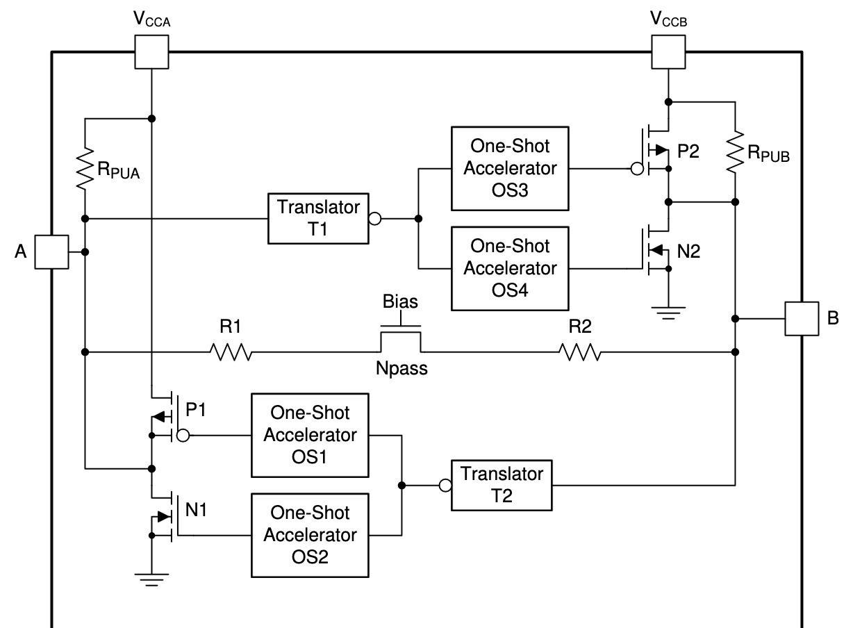
It’s conceptually similar to a TXS0104, but with many additions that are designed to support faster signal rates. Instead of a single one-shot to accelerate rising edges, there are separate one-shots to accelerate both rising and falling edges. The pull-up resistors aren’t fixed at 10K ohms anymore, but dynamically change their values depending on whether the signal is rising or falling. There’s also some extra resistance in series with the pass transistor.
The datasheet mentions a maximum data rate of 110 Mbps for push-pull, which is much faster than 24 Mbps on the TXS0104. Faster is better, right? Maybe not. The TXS0108 datasheet also contains a warning that’s not found in the TXS0104 datasheet:
PCB signal trace-lengths should be kept short enough such that the round trip delay of any reflection is less than the one-shot duration… The one-shot circuits have been designed to stay on for approximately 30 ns… With very heavy capacitive loads, the one-shot can time-out before the signal is driven fully to the positive rail… Both PCB trace length and connectors add to the capacitance of the TXS0108E output. Therefore, TI recommends that this lumped-load capacitance is considered in order to avoid one-shot retriggering, bus contention, output signal oscillations, or other adverse system-level affects.
Sparkfun sells a TXS0108 level shifter breakout board, and their hookup guide mentions struggling with this problem:
Some users may experience oscillations or “ringing” on communication lines (eg. SPI/I2C) that can inhibit communication between devices. Capacitance or inductance on the signal lines can cause the TXS0108E’s edge rate accelerators to detect false rising/falling edges.
When using the TXS0108E, we recommend keeping your wires between devices as short as possible as during testing we found even a 6″ wire like our standard jumper wires can cause this oscillation problem. Also make sure to disable any pull-up resistors on connected devices. When level shifting between I/O devices, this shifter works just fine over longer wires.
The TXS0108E is designed for short distance, high-speed applications so if you need a level shifter for a communication bus over a longer distance, we recommend one of our other level shifters.
This statement confuses me a bit. At first it says even a 6 inch wire is problematic, then it says it works just fine over longer wires, before concluding that you should choose a different solution if you need communication over a long distance. For disk emulation applications I may need to drive signals on a cable that’s several feet long. My take-away is that the TXS0108 is much more fiddly to use successfully than the TXS0104, and is prone to oscillation problems when circuit conditions aren’t ideal – which will probably be the case for me. Since I don’t need 110 Mbps communication, there’s no compelling reason for me to use the TXS0108 except the minor space and cost savings compared to a pair of TXS0104’s. I can run at slower speeds with a TXS0104 and hope to minimize problems with oscillations.
My conclusion? When selecting parts, read the datasheet, the whole datasheet. All three of these chips have nearly identical titles and descriptions on page 1, and it’s only after digging further down that their significant differences become apparent.
Read 4 comments and join the conversation4 Comments so far
Leave a reply. For customer support issues, please use the Customer Support link instead of writing comments.
I might have misunderstood the operation of the TXB0104, and perhaps it could also work for my application. In its datasheet there’s no spec for Ioh or Iol, the maximum current the chip can supply when driving an output high or low. Why not? This would imply the current is actually supplied by the external device that’s driving the pin, same as the TXS0104, but I don’t see how. The block diagram shows the output is driven by an inverter that’s internal to the TXB0104.
Page 17 shows a block diagram that’s somewhat different from the one I included above. It says “In a DC state, the output drivers of the device maintain a high or low, but are designed to be weak (they’re driven through a 4Kohm series resistor), so the output drivers can be overdriven by an external driver when data on the bus flows the opposite direction.” This seems problematic for multiple reasons.
Reason 1: The 4Kohm series resistor may interact with pull-ups and other resistors in undesirable ways. The B side of the shifter will be some ancient Apple II or Macintosh drive controller circuitry, which make frequent use of such resistors. For example if there’s a 10K external pullup to 5V on the B side equipment, and the TXB0104 is driving a low (0 volts) signal through the 4Kohm series resistor, it’ll form a voltage divider and the actual voltage at pin B will be 4/14 * 5V, or 1.43 volts.
Reason 2: Some of the chips that are used in old Apple disk controllers have anemic output currents when driving a logical high signal. I can’t find the reference at the moment, but if memory serves, the original IWM chip can only supply 0.4 mA for a logic high. That won’t be enough to overwhelm the “weak” driver in the TXB0104 and change the signal state. The datasheet mentions the device driving the data I/Os of the TXB0104 must have drive strength of at least 2 mA. I don’t think that can work for my application. The datasheet also contains the same warning about oscillations as the TXS0108 (but not TXS0104), so that’s another strike against it.
Another option would be something like the 74CBTD3384 or other FET switches in the same family – they will do bidir level conversion without any of the drawbacks you’ve listed above
Hmm, yes. That seems like a better solution in every respect… I’m not sure why anybody would choose the types of shifters that I first described. Maybe lower cost or wider availability?
The ringing issue Sparkfun encountering is signal integrity issues, and nothing to do with TXB or TXS, but rather any signal with fast edges must be treated carefully. It can be a 1mm trace or 10cm trace, both can have ringing issues. It all depends on the edge rate. Say, you have a mile long cable and you raise the voltage at one end very slowly, the voltages on the 1mile wire will be “same” at every point. But if you raise the voltage at one end very quickly, due to speed of light, etc. :), electrons can’t reach the other end fast, so you end up with a “rising voltage wave” that starts at your end and travels to the other end. Depending what device is hooked at the other end, the rising voltage wave may terminate or come back to your end (today’s circuits are designed for it to come back ONE time only). Then it reflects at the source and goes back to the destination, and then comes back. You end up with many such waves living on the wire. They add up and cause fluctuations, hence the ringing affect. Simplying a lot here 🙂 If the “trace” is not routed carefully with a “return path” (gnd), the “wave” will not be happy. One way to stop this back and forth is to terminate the signal (wave). This is done by having a series resistor at the source or another type of termination at the destination (more complicated than source termination).
Faster the edge, the worse “wave” affect. Both TXS and TXB have one-shot circuits that detect if the logic level is changing and then make it faster. To be truely automatic, bidirectional level shifters (as opposed to 245 series), these drive via 4K pull-up or pull-down at both ends. Then when any IC connected to TXS/TXB overrides this 4K pull-up or pull-down, that side wins, the one-shot circuits detect it and then it pushes the other side to match the winning side. If the one-shots didn’t exist, then the level shifting would be done by regular pull-up’s around a FET (usually 4K – 10K pull-ups, as seen in TXS family) which makes the rising edge slow because of the 10K pull-up (any pull-up is slow compared to push-pull in one-shot). Hence TI built these TXS and TXB chips with one-shots to make the edges faster for faster data rates. TXS is the standard FET w/ two pull-ups design for I2C applications. TXB is the 4K pull-up/pull-down at both ends for bidirectional. Why two families?
A major difference between the two is TXS can drive LOW very HARD by either side but TXB can not drive high or low HARD because TXB uses 4K pull-up or pull-downs. For IC’s and their inputs, 4K pull-up or pull-down works but if you were planning to drive an LED, TXB won’t work because LED will be pull-up/down with 4K (and won’t light up). On the other hand, TXS can drive LOW hard but HIGH weakly using 10K. This works for LED’s because we can connect LED to to VCC using 330Ohm. Hope this makes sense.
As you noticed, with TXB, the driving side must overcome 4K pull-up or pull-down. If your device has WEAK outputs (100uA I_OH, I_OL), then it won’t work w/ TXB. Then you need to use 245 type of solution and somehow know the direction ahead of time. If your IC has weak output on one logic level, let’s weak high output, in otherwords, it can drive low HARD but high WEAK, then you should use TXS family.
I’ve been using TXS and TXB extensively and learned a lot. They are great but not drop-in replacement. I looked into the 74CBTD3384. I’m always on teh look out for level shifters. Datasheet says it can do 5V to 3.3V level shifting but it is very sketchy about how it is done. It does mention internal diode. TI’s datasheet says they an internal ESD diode from 3.3V signal to the VCC (3.3V supply) to limit input signal voltage at 3.3V+V_diode but this is BAD design. It requires your 3.3V supply to be able to SINK current (5V -> ESD diode -> 3.3V rail) so the diode turns on and drops the voltage. This “sinking” action can also be done by other devices on the 3.3V supply (3.3V regulator or the 3.3V devices, it doesn’t matter who takes the electrons coming from 5V side). If devices don’t draw enough current and the 3.3V regulator is a simple LDO which doesn’t sink, then the sinking doesn’t happen, the 3.3V rail will rise up to 5V-V_drop (4.x V) and violate specs for 3.3V devices. Don’t tell me how I know this, I’ll just mention, some cars people pay hundreds of thousands of dollars make this mistake and I had to deal with it 🙂
Sorry for the long write-up, hope this was educational. Summary, be careful about edge rates and have good return paths.