

Classic Macintosh Video Signals Demystified, Designing a Mac-to-VGA Adapter with LM1881
In the late 1980s When Apple released its first Macintosh models supporting external color monitors, the company made some design choices that continue to cause trouble even today. Computers like the Macintosh IIci supported 640 x 480 video resolution, the same resolution as the VGA standard that was common in the PC world, but they used a different physical connector for the monitor cable, a different vertical refresh rate, and a different method of encoding sync information. It’s those sync differences that have proven to be most problematic over the years. Let’s look at what all is required to use my Macintosh IIci with a modern LCD monitor. Grab some coffee and get comfortable, because this will be a long one.
Monitor Connector Comparison
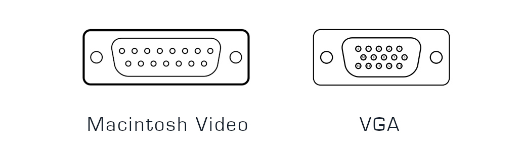
The classic Macintosh video connector is a DB-15, with two rows of pins. The correct name for this is actually DA-15, but nearly everybody calls it DB-15 and we’ll follow that convention. The VGA connector is a DE-15 with three rows of pins. This is sometimes called HD-15 owing to its “high density” arrangement of pins. Despite the physical differences, the video signals on the two connectors are mostly the same: (pinout data from sfiera)
| Signal | Mac | VGA |
| Red video | 2 | 1 |
| Red ground | 1 | 6 |
| Green video | 5 | 2 |
| Green ground | 6 | 7 |
| Blue video | 9 | 3 |
| Blue ground | 13 | 8 |
| HSYNC | 15 | 13 |
| HSYNC ground | 14 | 5 |
| VSYNC | 12 | 14 |
| CSYNC | 3 | NC |
| VSYNC/CSYNC ground | 11 | 10 |
| Sense 0 | 4 | NC |
| Sense 1 | 7 | NC |
| Sense 2 | 10 | NC |
| Ground | shell | shell |
This difference in physical connectors is fairly easy to solve with an adapter. During the 1990s and 2000s you could find a Mac-to-VGA adapter at any computer store. Today they’re more rare, but still available from surplus electronic suppliers or eBay.
Signals and Sync
A very brief primer on video signal formats: A video signal is composed of a series of lines, organized into frames. The lines are output from the video hardware one by one, at a fixed rate, and the timing of each line is indicated with an HSYNC pulse from the video hardware. After all the lines in a frame have been output, there’s a VSYNC pulse before the start of the next frame. The monitor needs these sync pulses to keep its display operating in lockstep with the video signal.
The 640 x 480 VGA standard uses 60 frames per second – its vertical refresh rate is 60 Hz. But Apple chose a 67 Hz refresh rate for its 640 x 480 video format (actually 66.666666…), which could be argued is slightly better than 60 Hz because the higher rate results in reduced flickering on CRTs. The difference is negligible, however, and the 67 Hz rate only serves to complicate things. Fortunately most modern moderns support a fairly wide range of vertical refresh rates, where a range like 50-75 Hz is common. This means that the 67 Hz refresh rate usually isn’t a problem. If you know of a counter-example, please tell me.
What about those sync signals? In the VGA standard, HSYNC and VSYNC are provided as separate input signals on VGA pins 13 and 14. It’s nice and simple, end of story. But in the classic Macintosh video world, sync is… complicated. There’s a fair amount of misunderstanding and myth about this topic floating around the web, so I’m here to explain the truth. From the table above we can see that the Mac has outputs for HSYNC and VSYNC, but also for CSYNC composite sync (HSYNC xor VSYNC). Many people have also heard about sync on green, where composite sync is mixed directly into the green video channel. So what exactly is the Mac video sync standard? Does it output separate HSYNC and VSYNC, or CSYNC, or sync on green?
The answer is yes, the Mac generates all of those sync standards at different times, depending on what type of monitor it thinks is connected. But it doesn’t generate all of them all of the time. The video hardware checks the voltages on the connector’s three sense pins, which form a 3-bit monitor ID for the connected monitor type. If it’s a supported monitor type, the video hardware configures itself for an appropriate output signal and sync method. If it’s not a supported monitor type, the video hardware shuts off and outputs nothing.
Here’s a page from a Macintosh IIsi hardware developer note. The IIsi’s video hardware is nearly identical to my IIci:
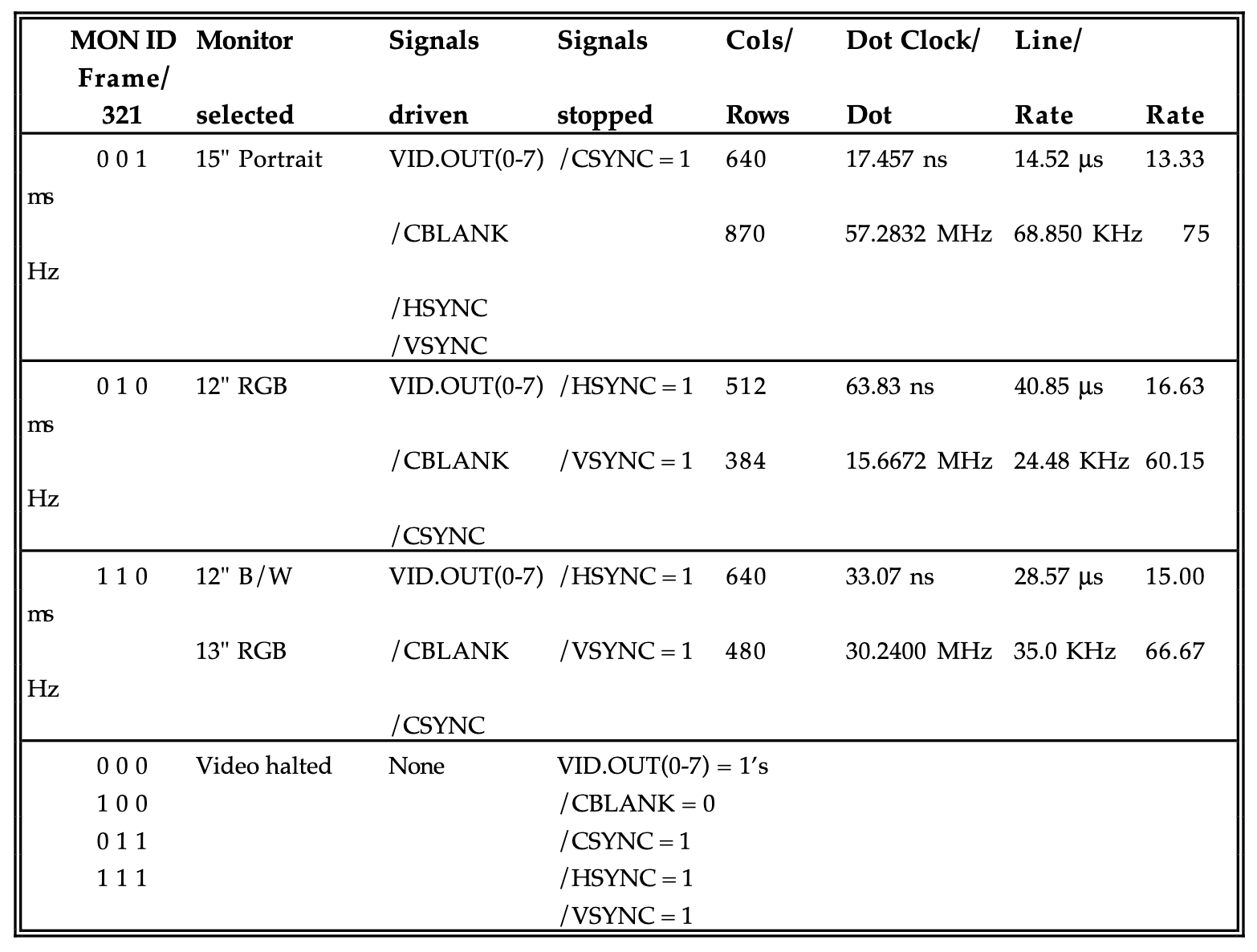
We can see that four different types of monitors are supported, but two of them share the same monitor ID and signal format. For a 15 inch portrait monitor, the Mac outputs separate HSYNC and VSYNC signals exactly like VGA requires, but at the mostly-useless portrait resolution of 640 x 870. For the 13 inch RGB monitor standard that we’re interested in, with 640 x 480 resolution, HSYNC and VSYNC are stuck high and the sync information is provided via CSYNC.
What about sync on green? Although it’s not mentioned anywhere in the developer note, the Mac also outputs sync on green any time it outputs composite sync. It outputs both CSYNC and sync on green. In fact, it also outputs sync on red and sync on blue too – all three color channels have embedded sync information when composite sync is used. This was recently proven conclusively with a video hardware schematic analysis followed by a series of tests by dougg3 (Doug Brown), who kindly gave me permission to reproduce his oscilloscope captures here.
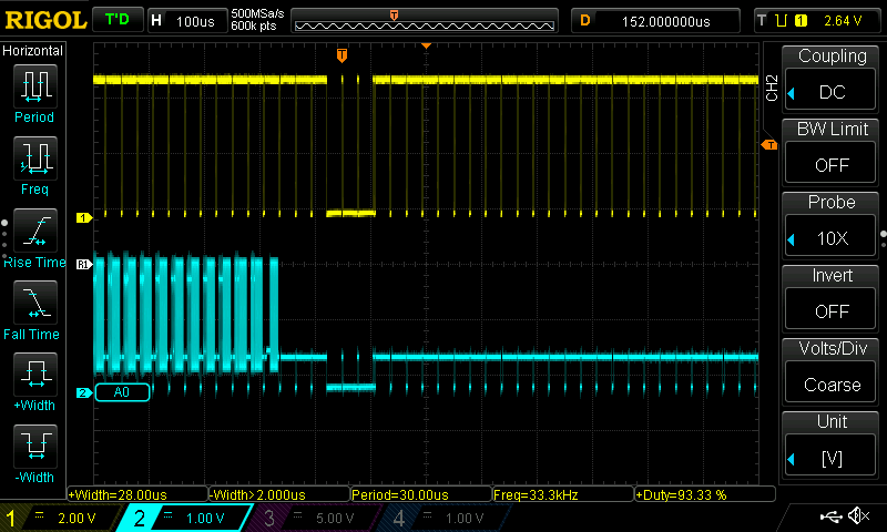
Doug hotwired his IIci’s monitor connector, grounding pin 4 (sense 0) to produce the monitor ID for 640 x 480 RGB. He made this scope capture showing the Mac’s CSYNC output (yellow trace) and red video signal (cyan trace). On CSYNC you can see the shorter HSYNC pulses and the longer VSYNC pulse combined with the HSYNC pulses during it. On the red channel, you can see some red video data on the left, with the sync info clearly also present in the lower voltage range.
Looking at the green channel also showed the same thing – embedded composite sync in the green video data. Doug then looked at the VSYNC output (cyan trace):
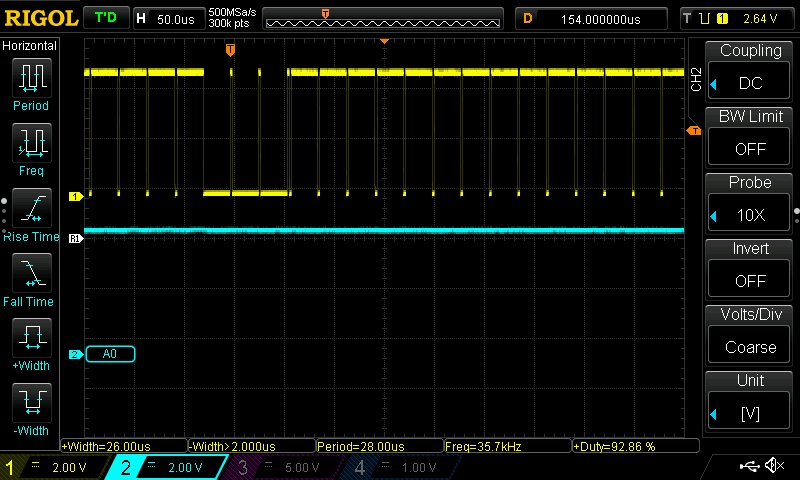
Nothing. VSYNC was just a constant high voltage. Nothing to see here. This confirms the information from the developer note: when CSYNC is output, VSYNC and HSYNC are turned off.
DIP Switch VGA Adapters
Now we know enough to begin peeking inside the common Mac to VGA adapters, with their confusing arrays of DIP switches, to understand how they work. If you’ve been around classic Macintosh computers for a while, you’ve surely seen many variations of these:
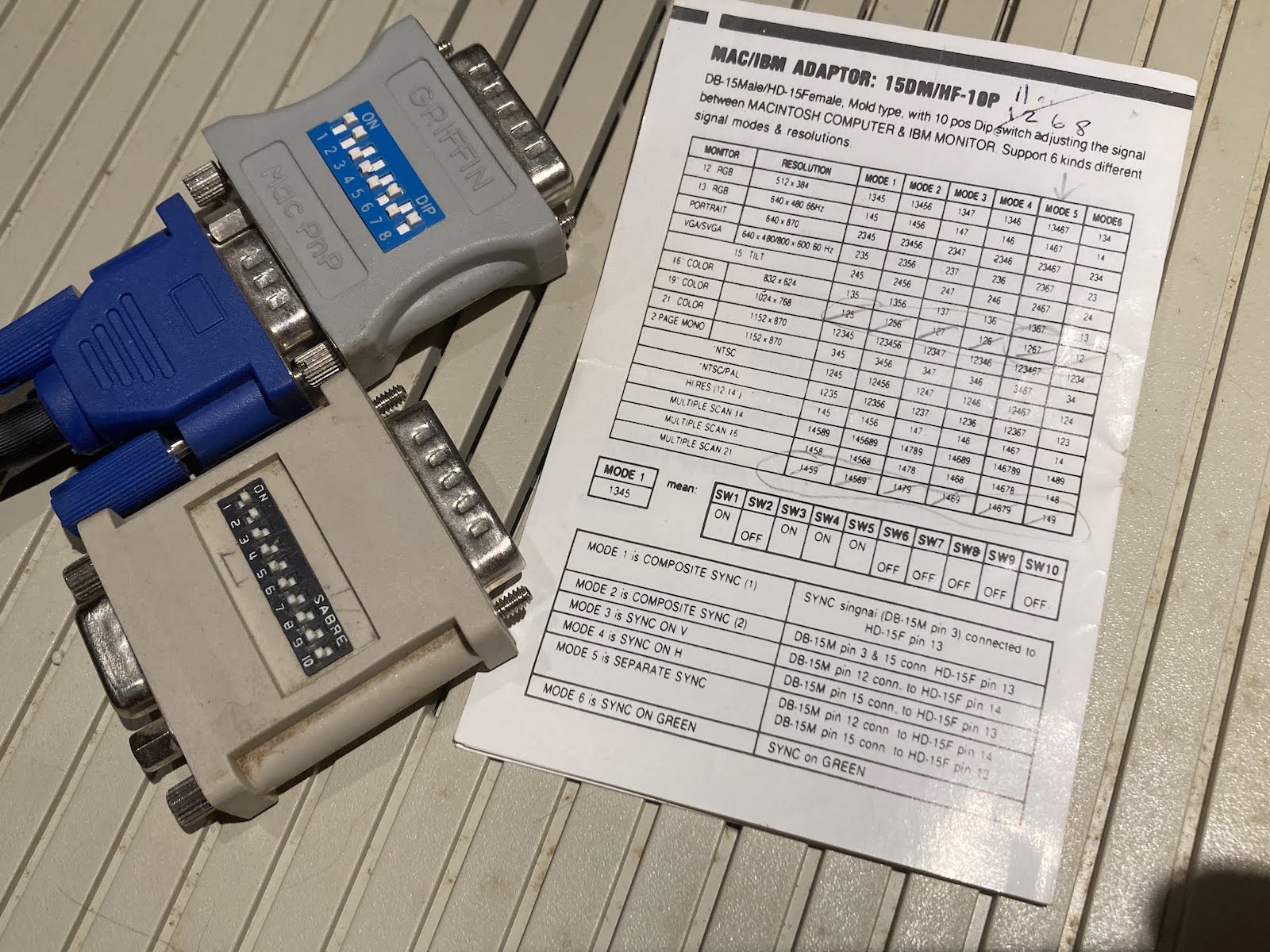
Obviously they are physical adapters from DB-15 to HD-15, but what do all those DIP switches do? For nearly all such adapters, the guts are simply a passive switch matrix, controlling how the Mac pins are connected to the VGA pins. There’s no signal processing of any kind. The DIP switches typically perform two functions:
Monitor ID – Configure how the sense pins are connected to ground, or to each other, to set the desired monitor ID. This tells the Mac what kind of video signal to generate.
Sync mapping – VGA VSYNC can optionally be connected to Mac VSYNC. VGA HSYNC can be connected to Mac HSYNC or Mac CSYNC.
They’re pretty simple devices. Maybe you’re wondering why you’d ever want to connect the Mac’s CSYNC to the VGA monitor’s HSYNC. Many newer monitors are able to accept composite sync as an alternative to HSYNC and VSYNC, and if they have that capability, they will normally expect CSYNC on their HSYNC input. Providing a DIP switch mapping for this will enable the Mac to work directly with such monitors.
Note that there are no DIP switch settings related to sync on green. If the monitor supports sync on green, it will use the sync info in the green video channel with no extra configuration needed. If the monitor doesn’t support sync on green, too bad.
The Sad Tale of One Macintosh IIci, Four Monitors, and No Joy
Are you still awake? With all of this background exposition finished, we’re finally ready to tell the story that inspired this whole investigation. It’s the story of my Macintosh IIci, four different monitors, a host of different Mac-to-VGA adapters, and a lot of frustration leading to eventual understanding and the design of a new video adapter.
For several years I’ve been using my Macintosh IIci with the Griffin Mac PnP adapter pictured above and a Dell 2001FP LCD monitor, and it’s worked great. This particular monitor also has a composite video input that works with Apple II and other classic computer hardware, so it’s an excellent tool for computer collectors. As to exactly how the Mac IIci video worked with this monitor, I never gave it any thought. I just plugged it in and got a picture.
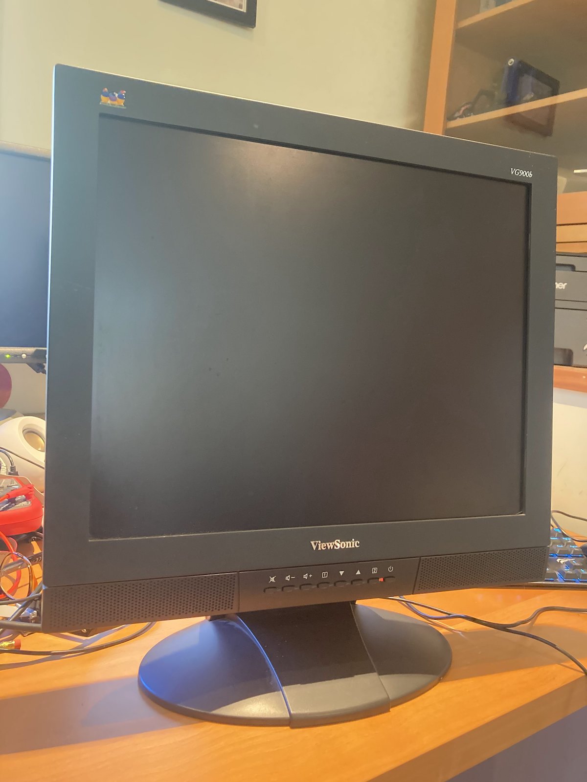
A couple of weeks ago I went on a shopping spree and purchased a ViewSonic VG900b 19-inch LCD, a Viewsonic 6 TX-14H30 14-inch CRT, and an E-Machines ColorPage T16 II 1108DT16MR 16-inch CRT. These are all multisync displays, with a max resolution of 1024 x 768 on the CRTs and 1280 x 1024 on the LCD. But when I connected them to my Mac IIci with the Griffin adapter, I got no picture from any of them. I tried zillions of DIP switch settings, I tried different adapters, but nothing helped. All three of these fussy monitors simply refused to show any image from my IIci. They behaved as if nothing were connected.
Now that we understand the video signals and the inner workings of the DIP switch adapters, we can see the likely reason that nothing worked. In 640 x 480 mode the Mac IIci outputs composite sync and sync on green. My 2001FP must support one or both of those sync standards, but the new monitors probably don’t support them. In the case of the VG900b this was confirmed in the hardware specifications listed in its manual, where it lists support for “H/V Separated (TTL)” video sync. Other Viewsonic LCDs from the same era specifically mention composite sync and sync on green in their specifications, so this isn’t likely just an accidental omission from the documentation. I haven’t been able to find detailed specifications for the two CRT monitors, but I’m guessing it’s the same issue. These monitors require separate HSYNC and VSYNC signals, and won’t support any other sync format.
LM1881 to the Rescue
What do you do when your computer outputs composite sync, but your monitor requires separate HSYNC and VSYNC? Say hello to the Texas Instruments LM1881 Video Sync Separator.
This chip is designed to extract composite sync from composite video, a video standard in which composite sync is mixed with RGB color data. In our case the composite sync is already separated from the color data and doesn’t need to be extracted, but the LM1881 has another feature we can take advantage of: synthesis of a separate VSYNC signal from the composite sync input. Unfortunately the LM1881 doesn’t have a complementary HSYNC output. There are other rarer and more expensive chips that can extract both HSYNC and VSYNC, but I haven’t investigated these.
Fortunately for us, I’ve learned that many (most?) monitors will accept CSYNC as a substitute for HSYNC, so long as a separate VSYNC signal is also provided. So all we really need is VSYNC, and the LM1881 can do the job.
Armed with this information, I set out to build a Mac to VGA adapter with an integrated LM1881 that would enable my Macintosh IIci to work on those three fussy monitors. I would use the LM1881 to extract VSYNC from CSYNC, passing the VSYNC to the VGA monitor, and I would pass CSYNC to HSYNC with my fingers crossed.
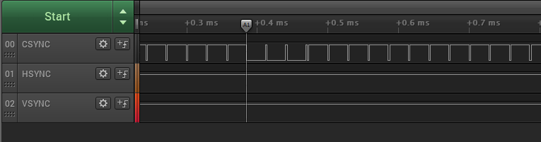
I began with a DB-15 breakout. I connected up all the grounds, and grounded pin 4 (sense 0) to request Mac 13 inch 640 x 480 mode. I plugged the breakout into my Macintosh IIci, and connected a logic analyzer to all three sync outputs. CSYNC showed the expected composite sync with a period of 15 ms (66.67 Hz), while HSYNC and VSYNC remained high.
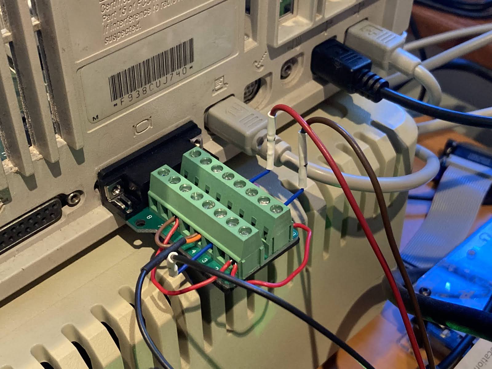
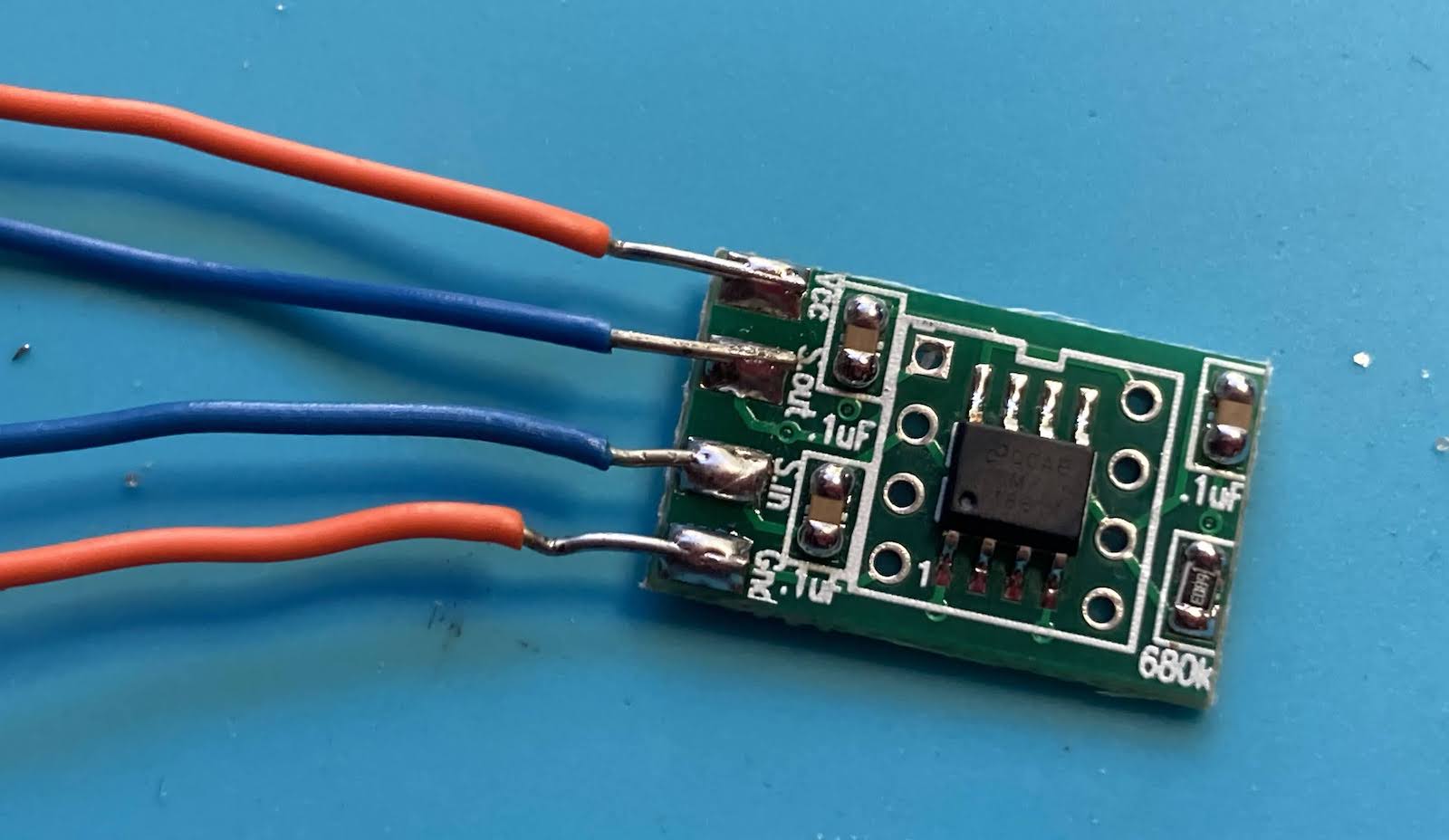
Next I soldered some wires to an LM1881 breakout PCB. The LM1881 requires a 5V supply, which isn’t present on the monitor connector, so I stole 5V from the floppy disk port. Later I intend to try self-powering the LM1881 using the (otherwise unused) VSYNC and HSYNC signals as a power source.
Examining the LM1881 composite sync output, I saw that the output followed the input as expected.
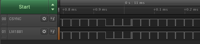
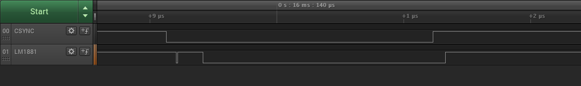
But zooming in, the signals were not quite the same. The LM1881 output lagged the CSYNC input by about 100ns, and included a very short low pulse before going high and low again, for each pulse on the CSYNC input. This might have been an artifact of using a logic analyzer to view the signal, rather than an analog oscilloscope.
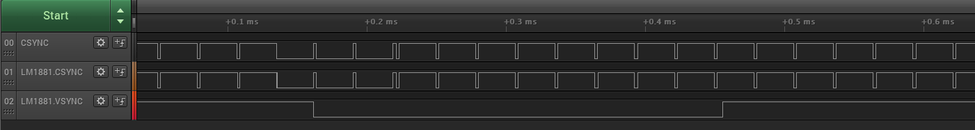
Then I soldered another wire to LM1881 pin 3, the synthesized VSYNC output. It worked! But the extracted VSYNC lagged the input VSYNC by a whole line, and extended several lines past the end of the input VSYNC. This was unexpected, but I believe the exact timing and duration of the VSYNC signal isn’t critical, so long as the refresh frequency is correct.
So far, so good. I finished the adapter by adding an HD-15 breakout. I connected the LM1881’s VSYNC output to VGA VSYNC, and LM1881 CSYNC output to VGA HSYNC. Remember, this second connection isn’t really correct – CSYNC is not HSYNC – but we’re relying on the premise that monitors will accept CSYNC on their HSYNC input as long as they also have a separate VSYNC signal. Thanks to the LM1881, we now had that missing VSYNC signal.
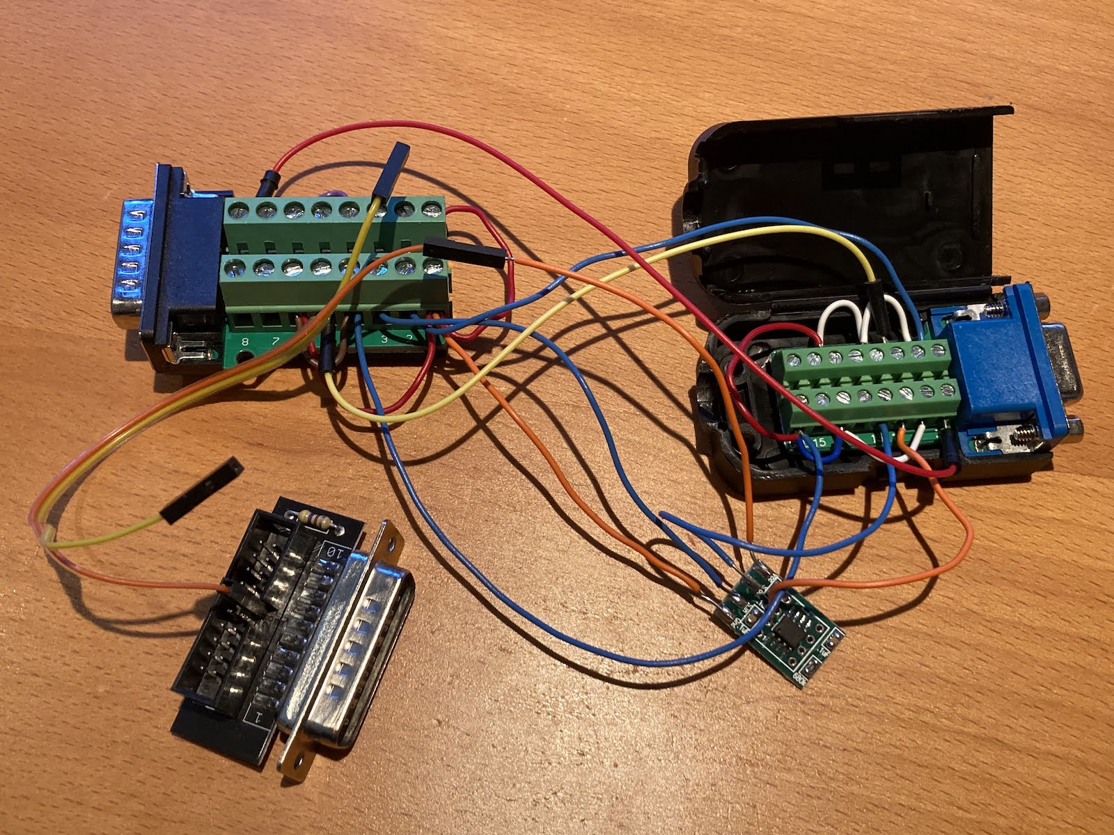
Here’s the finished adapter, including the floppy port adapter for stealing 5V: it really is a big mess o’ wires, and something so ugly that only a mother could love it.
I’ve mentioned that I have one monitor that’s worked with my IIci’s built-in video all along: the Dell 2001FP. And three monitors that do not work, no matter what settings I have tried on the VGA adapters: the Viewsonic VG900b LCD, Viewsonic 6 CRT, and E-Machines CRT.
As a sanity check, I tried the Dell first:
It still worked, but the video quality was lousy: there was all kinds of shimmering and noise in the image. Maybe it was a result of my messy nest of wires snaking everywhere? At least there was a usable image.
Next I tried the Viewsonic VG900b LCD. This was the real test, since this monitor had refused to sync with my IIci video before. Would it work now?
Whomp whomp, so sorry. There was no love from the VG900b, which still complained there was no video signal and then went to sleep. That was disappointing. Maybe the VG900b doesn’t like CSYNC as HSYNC substitute, or maybe it’s confused by the CSYNC that’s also still present on the RGB channels.
OK, how about this Viewsonic 6 CRT? It never worked with the IIci video before, but how about now?
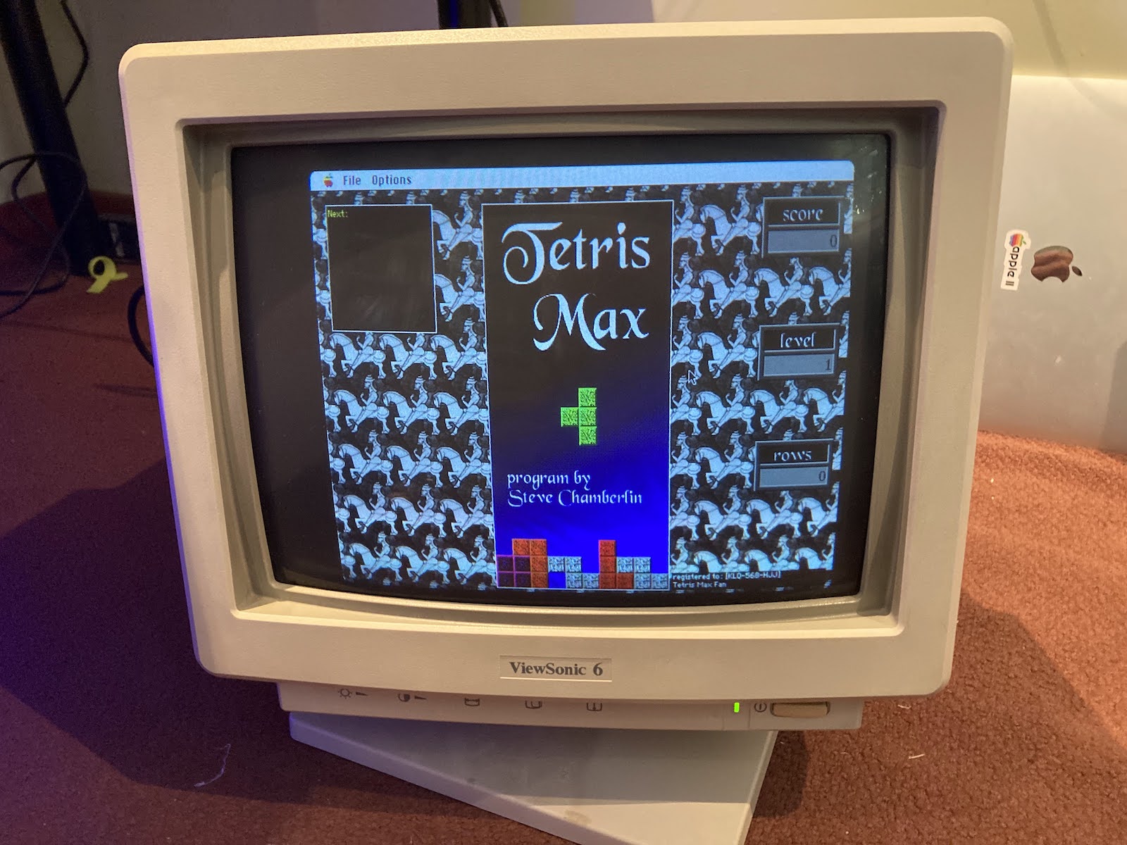
Success, it worked! The image quality was pretty good too. There was still a little bit of shimmer, but much less than with the Dell 2001FP. I’m not sure why there was such a difference, maybe something about digital versus analog video circuitry?
The final test was the E-Machines 16 inch CRT. This was the third member of the fussy trio that had refused to work with my IIci built-in video before:
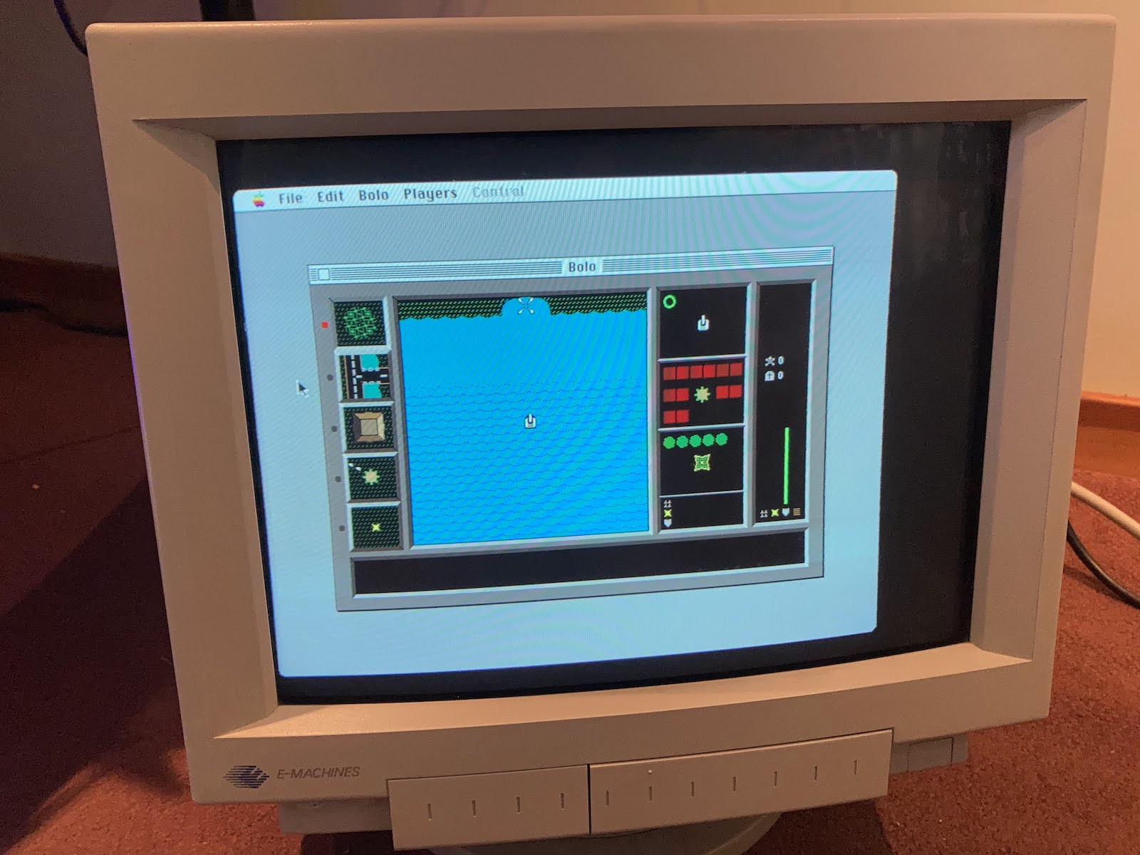
Huzzah! It also worked (minus some image centering). The image quality was similar to the Viewsonic CRT: some shimmer, but not too bad.
Design of a New Mac-to-VGA Adapter
That’s a score of 2 out of 3 for this Mac-LM1881 adapter. I think that’s useful enough to deserve being made into a proper PCB kit, for other classic Macintosh computer owners who’ve faced the same monitor challenges. Since it’s such a simple circuit, I’ll probably share the whole PCB design for anybody who wants to make their own, and also stock a few in the BMOW store for anybody that wants a pre-built adapater.
To assist with troubleshooting, I’d also like to include some LEDs in the adapter to show which of the Mac sync outputs have activity, and maybe also which of the RGB outputs have activity. I haven’t quite figured out how to do this. The RGB outputs are only 0.7V, and may have negative voltage swings if sync on green is used. The sync outputs are standard TTL levels with 0 to 5V swing. I’ve been brainstorming how to build an “activity detector” circuit to turn on an LED without involving a microcontroller. Maybe something with a flip-flop where the sync signal is used as the clock input, and there’s an RC circuit with appropriate time constant connected to the flip-flop’s asynchronous clear. If you have any great ideas for this, please share them.
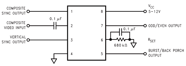
Some questions about the LM1881 remain. I belatedly read the chip’s data sheet only after I’d finished my experimentation, and realized that I may be using it incorrectly, and that many of the similar circuits seen on the web are using it incorrectly. Referring to the canonical LM1881 circuit diagram shown above:
- Why didn’t the Viewsonic VG900b work with the LM1881 sync signals? Is there something simple I could do to fix it?
- The datasheet says the recommended input voltage on pin 2 is 1.5V and the absolute max is 3V, but I’m feeding it a 5V sync signal from the Mac.
- A different RC filtering scheme on input pin 2 may be needed – the 0.1 uF blocking capacitor is just an example. “Typical Applications” in the datasheet shows an alternative design with an RC lowpass filter on pin 2.
- The value of the R-set resistor may need to be adjusted, depending on video timing. The default value of 680 kOhm may be inappropriate for this.
- The LM1881 output pins can only source a few mA of current, but if I’m putting 5V into a 75 ohm terminated monitor input, won’t that be 67 mA? Do I need to buffer these signals? 67 mA is a pretty large amount of current, and more than even most buffers can provide. Perhaps I’ve misunderstood this. Do I also need a 75 ohm resistor at the source? Does 75 ohm termination even apply to the sync signals, or is that only for the RGB signals?
The investigation continues. More updates soon, I hope!
Read 19 comments and join the conversation19 Comments so far
Leave a reply. For customer support issues, please use the Customer Support link instead of writing comments.
Some attempts to answer my questions 1-5.
1. I still don’t know why the Viewsonic VG900b didn’t work, but it seems unlikely there’s anything easy I can do to fix it. My best hope is it failed due to poor signal quality of the sync signals, and a nice PCB would give better signals than my mess of wires. If the VG900b didn’t work due to the refresh rate, or the presence of sync on green, there’s nothing I can do about it. If it didn’t work because it won’t accept CSYNC as HSYNC, I’d need a different more complex chip to solve that. That feels like a project for another day.
2. Yes, I should probably be reducing the voltage from the Mac’s CSYNC output before connecting it to the LM1881’s pin 2 input, to avoid exceeding the maximum DC voltage rating. A simple voltage divider should work. The chip is designed to work with composite video input with 1 Vpp, not 5V signals.
3. I think input filtering is mainly only needed for actual composite video sources where a noisy video signal causes false CSYNC triggering. For this application, I think the basic 0.1 uF blocking capacitor should be fine.
4. The R-set resistor controls several behaviors at once. If the circuit is working OK as-is, then there’s no reason to change the default 680K value. If R-set is too low there will be two VSYNC output pulses, if R-set is too high there will be no VSYNC pulse. R-set also controls the length of the VSYNC pulse and the burst / back porch pulse (not used here). There may be room to reduce R-set somewhat, especially if higher resolutions than 640×480 are desired. Maybe a value like 500K would be good for common Mac video resolutions.
5. I’m still unsure about the impedance and current requirements for the sync outputs, but I think everything’s probably OK as-is, or maybe I could use a simple buffer like a ‘244 for the sync signals. My reasoning: 1) In normal operation the Mac provides the sync signals, and I very much doubt it can output 67 mA. Schematics show the video chip’s sync outputs are driven through 180 ohm series resistors. 2) One source says only the RGB signals are terminated with 75 Ohm, and the sync signals are high impedance. 3) The VESA standard says synchronization signal lines should be terminated with 2 kOhm to +5 V (not 75 ohm). 4) I found the datasheet for a VGA buffer chip that lists a max current for its sync outputs of 8 mA, nowhere near 67 mA.
A possible solution for the activity detection LEDs on the sync signals is a monostable multivibrator like 74HC123. I need to understand this more, but I think this could be configured such that its output is normally low, but a rising edge on its input produces a short high pulse (with duration tunable through external RC values). If the sync input is constantly changing then it will keep retriggering and the output will be constantly high and can be used to light an LED. But if the sync input is constant (either high or low) then the output will be low and the LED will remain off.
Once challenge will be squeezing all this into an adapter. People expect such adapters to be small, but this needs to fit a DB-15, HD-15, LM1881, 74HC123, DIP switches, LEDs, and passive components. The LM1881 and 74HC123 are only available in large-ish package sizes, too. So the physical size of this adapter might be awkwardly large. It can’t be wide because then it might block adjacent ports on the computer, so it will need to be long.
“So the physical size of this adapter might be awkwardly large. It can’t be wide because then it might block adjacent ports on the computer, so it will need to be long.”
The adapter does not have to hang at the back of the monitor or the back of the computer. Use a PCB with Mac and VGA connectors at opposite sides, put it into a common of-the-shelf case (preferably some metal case for shielding), and connect both the Mac and the monitor via cables. That box can be hidden somewhere behind the monitor or the computer with no excessive mechanical stress on the connectors.
Good thought. I’d hoped to avoid the need for a DB-15 to DB-15 cable, but it could be a good option if the adapter is too large to work as a dongle.
Another option would be a (relatively short) fixed cable from the Mac to the adapter box, using a good strain relief at the adapter box. You could even use the same PCB and the same case as with the two-cable variant, you just need a different front plate at the Mac side of the box (single hole for cable and strain relief instead of DB-15 cut-out and mounting holes). The cable would simply be soldered to the footprint of the DB-15 connector.
Personally, I really don’t like adapter boxes with a fixed-lenth cable. The cable is always either too short or too long, the strain relief is rarely both good and pretty, and the cable quality is often sub-par. An adapter box with connectors allows me to choose good cables, and if I want, I can buy or build my own cable with the perfect length.
Some random thoughts:
A monitor that does not implement sync-on-green will simply ignore the sync pulses on the green channel, and due to the lack of other sync signals, it won’t display anything (except for a “no signal” OSD). PC VGA never had sync-on-green (except for perhaps one or two very special cards), so monitors designed with a PC VGA in mind simply won’t have a sync sepeator on the green input. The same is true for composite sync. VGA always delivered separate sync signals, so no hardware was needed for separating the c-sync signal. Older monitors were designed to work with non-PC hardware, like SGI or Sun (remember the 13W3 connector?), and those hat c-sync and/or sync-on-green. Interestingly, almost all my pinout sources list pin 13 of the VGA connector as “h-sync or c-sync”.
Feeding extra v-sync pulses into the h-sync input might in fact confuse the sync circuit in the monitor. Remember that the monitor tries to synchronize its horizontal oscillator with the h-sync signal. Adding low-frequency noise a.k.a. v-sync signals makes that harder.
The LM1881 expects an NTSC composite video signal (or something very close to that) at pin 2, with the usual level of about 1 V terminated into 75 Ohms. The termination happens somewhere else, together with the handling of the video signal, so pin 2 is relatively high impedance. If the Mac really emits c-sync with 5 Vpp, you surely should divide that down.
There are other ways to separate h-sync and v-sync signals. The LM1881 is really designed for NTSC SD-TV, and not much else. A quick search resulted in the LMH1980 by TI. Like the LM1881, it accepts NTSC SD-TV, but it can also be used for HD and PC video signals and PAL. And unlike the LM1881, it emits true h-sync and v-sync signals. According to the datasheet, it has a much smarter sync handling, it automatically adjust itself to varying sync speeds after about two frames. I also found the ES1883 by Intersil/Reneas, but I think it is no longer produced. Like the LMH1980, it has true h-sync and v-sync outputs.
Regarding sync-separator ICs expecting composite video signals:
Those ICs work by comparing the video input voltage with a more or less fixed reference voltage (black level). The black level is usually set to 0 V by using AC coupling. Sync pulses are negative (0.3 V) relative to the black level, picture is positive (up to 0.7 V at full white). The color burst (if present) is symmetric around the black level. (See http://martin.hinner.info/vga/pal.html for nicely drawn video signals. Ignore the PAL in the URL, it’s the same principle in NTSC, just some timing differences and a different way to encode colors.)
If you feed a c-sync signal into the c-video input, the IC needs to accept that signal as completely black picture without color burst. So the c-sync signal should have a level of 0.3 Vpp (see also LMH1980 data sheet, electrical characteristics, input sync amplitude).
@Tux2000 thanks so much, this is all great feedback! You’re absolutely right that including VSYNC in the HSYNC input might confuse the monitor, and maybe this is why I can’t get the VG900b. I’m only using this method because I don’t have a simple alternative, and because other people seem to have used the same method successfully when VSYNC is also provided. It did work on 2 out of 3 monitors so it’s not completely useless.
I might start over later with an LMH1980, perhaps in a Version 2 adapter, but at the moment I’m under some time pressure to wrap up this LM1881 design and get it built ASAP. I’ll be happy if it solves video problems with some monitors, even if it doesn’t work for all of them.
Regarding sync on green, I have read that some monitors may get confused by the extra sync information in the color channel, resulting in incorrect black levels or washed out colors. I wouldn’t expect it to cause loss of sync if another valid sync signal is provided, but I can’t say for sure.
I’ve finished an initial schematic for the adapter, which you can view here: https://www.bigmessowires.com/wp-content/uploads/2023/10/mac-vga-lm1881.png
I tried to keep the behavior of switches 1-9 identical to other commercially-available Mac VGA adapters. I’m not sure I got the directions of the diodes correct for switches 8 and 9. Switch 10 connects the LM1881 VSYNC output to VGA VSYNC. Notice that the LM1881’s VSYNC is driven through a 180 ohm series resistor, which is termination voodoo that I copied from the VSYNC output in the Mac IIci schematics. I don’t know why it’s not 75 ohms, and maybe it could be omitted. Also notice that the LM1881’s CSYNC output isn’t used for anything. Since it’s essentially identical to the Mac’s CSYNC output, I just use that instead.
The LM1881 set resistor (R3) was lowered from the standard 680K value to 510K. I’m not sure this is needed, but I think if this adapter were ever used at higher resolutions there’s a chance that 680K would result in the “no vsync pulse” problem mentioned in the datasheet. It may take some experimenting to get the right value here.
The Mac’s CSYNC goes through a voltage divider to reduce it from 5V to about 1V for the LM1881. I’m not sure if this is actually necessary, but it makes it look more like the composite video input the LM1881 expects. In testing with my prototype, this didn’t make any obvious difference.
The adapter will attempt to self-power through a rectifier on all three Mac sync outputs. I have some doubt this will work, since it seems like the diode drop and losses from the Mac’s termination resistors would result in a self-power voltage well below 5V, but this AppleFritter thread from 2005 says it worked. Initially I had a switch to select between self-power and external power, but I ran out of space and just connected them directly. Because of the diodes, if you connect an external 5V supply at J3 then the adapter will draw power from that instead of self-powering.
The 74LS123 one-shot controls the blinkenlights. If I’ve calculated correctly, each falling edge on the Mac’s CSYNC or VSYNC will turn on the corresponding LED for 22 ms. As long as falling edges keep coming at least once every 22ms, the LED will stay lit. I couldn’t figure out a simple way to trigger the same one-shot from both VSYNC and HSYNC without adding more hardware, so it only checks for activity on VSYNC. But based on what I’ve learned about the Mac video hardware, if VSYNC is active then HSYNC will also be active and vice-versa. I still need to add a decoupling capacitor for the ‘123. The whole LED business could be scrapped if it uses too much PCB area or power.
“I have read that some monitors may get confused by the extra sync information in the color channel, resulting in incorrect black levels or washed out colors.”
That is in fact the case. When I was working on the NetBSD driver for the SGI O2 framebuffer, I had to add an ARC knob to disable sync-on-green — the sync pulse turned the black background into a greenish-black background.
C-sync power divider: Use an oscilloscope. Really. You want the black level at 0.3 V.
Stealing power from other signals: You can reduce the voltage drop by using schottky diodes instead of regular silicium diodes. Also, you should avoid as much load as possible, to avoid affecting the signal quality. In other words: Get rid of the LEDs and the LS-TTL chip, If you really need the LEDs, use high efficient LEDs and drive them with way less than 1 mA, and replace the LS-TTL chip with a CMOS chip (4538 looks promising, or use the 74HC123).
TTL vs. CMOS (1): When using TTL chips, don’t drive load to GND, drive it to the supply voltage. TTL outputs are very asymmetrical (unilke CMOS), they can sink way much more current than they can source, and with less voltage drop. In case of the LS123 the output current is max. 400 µA for high level, 8 mA for low level. So if you want to keep the LS123, connect the cathodes of D6 and D7 to the inverted output /Q (Pins 4 and 12) and the anodes via R1 and R2 to +5V.
TTL vs. CMOS (2): Another disadvantage of TTL chips is the input current, expect up to 400 µA at low level for the L123 that will disturb your sync signals. CMOS chips are driven by voltage, not current like TTL.
LM1881 Rset: The role of this resistor is to set up the ENTIRE timing of the LM1881. The block diagram in the datasheet is not really helpful, but it contains a hint. Rset is connected to a box labelled “capacitor charge current”. The main reason why that resistor is not integrated in the LM1881 is that it is very hard to put a resistor with a reasonably precise value on a chip without resorting to laser trimming. Resistors on a chip have tolerances of 20% and more. (See http://www.designinganalogchips.com/ for details.) Rset, togeter with the internal voltage regulator (drawn at pin 8) defines the reference current for charging probably all timing-related internal capacitors. Expect a lot of current mirrors on the chip. The Rset value can be guessed from the “typical characteristics” diagrams, especially figure 2. That’s what the datasheet recommends.
LM1881 supply voltage: The datasheet lists no minimum supply voltage. The “typical connection diagram” shows 5 to 12 V, and there is an abs. max. rating of 13.2 V, but there is no explicit minimuum supply voltage. The voltage at Rset (Pin 6) is typically 1.22 V, so there is a lot of headroom to 5 V. Figure 6 shows suppy current vs. supply voltage, the chip starts drawing current at a little bit below 4 V, and the current becomes linear at about 5 V. My guess is that the LM1881 should still work fine at about 4.5 V.
Thanks again! The CSYNC signal from the Mac has 0 to 5V swing. Are you suggesting to adjust the voltage divider to make it 0 to 0.3V, before the C1 capacitor?
The ‘123 is indeed the 74HC123 not 74LS123. I didn’t have the HC part available in my library so I used the LS part in the schematic.
Good idea on the Schottky diodes for self-powering, I will change that.
I’m not sure how much current is needed on the LED to make it visible, but I will experiment. I was thinking at least a few mA would be necessary. I could switch the polarity of the LEDs using the /Q outputs of the ‘123, and have them connected to +5V instead of GND, but for the HC part I don’t think it matters either way.
Yes the whole arrangement with the LEDs could be eliminated if necessary for power saving, but I really like the idea for troubleshooting purposes. With other adapters, it’s frustrating to plug in a monitor and set the DIP switches and get no picture, and have no idea what’s happening.
Thanks for the analysis of the LM1881 supply voltage. I found it curious that the minimum supply voltage wasn’t listed anywhere in the datasheet specifications
I thought of two more experiments to try with the VG900b before I completely give up on it.
1) Maybe this monitor’s input impedance on VSYNC is lower than the others, and the LM1881 output isn’t strong enough to drive it directly. I’ll try measuring the voltage while the monitor is connected. If that’s the problem, I can add a buffer to increase the output drive.
2) I could try using the BURST output as an HSYNC signal for the monitor. It will have a pulse at the correct horizontal frequency, without any other information mixed in. But the timing within the line will be wrong, it might cause the image to be shifted horizontally, or it might not work at all.
C-sync: Yes, I would divide the signal down to a swing of 0 to 0.3 V, perhaps a little bit more before C1. The LM1881 expects a composite video signal of 1 Vpp, that’s the difference between the lowest level of the sync pulses (0.3 V below black level) and the highest level of image data (full white, 0.7 V above black level). The c-sync signal lacks all image data (and the color burst), so it swings only between black (0.3 V) and sync (0 V).
74HC123: That’s a CMOS chip, with an input leakage current of 0.1 µA (25 °C) to 1 µA (-40 °C to 85 °C), and symmetrical output drivers capable of sinking and sourcing 25 mA (abs max). With that IC, driving the LED from the non-inverting output to GND is fine. Driving from the inverting output to +5V would work as well. So, no change required.
LEDs: You can get high efficiency LEDs, with high brightness at a ridiculously low forward current. A quick search at my prefered electronics dealer resulted in the Kingbright L-7104LID. It’s a red GaAsP/GaP LED, 3 mm diameter, viewing angle 40°, wavelength 625 nm, DC forward current 2 mA, forward voltage 1.7 V (typ) / 2.5 V (max). It should still be visible at even lower currents.
LED resistor: The 74HC123 has almost no voltage drop, the schottky diodes will drop about 0.4 V, less if you can get the current down. Let’s assume a supply of 4.5 V, and design for 1 mA. We need to drop about 2.8 V, so the LED resistor needs to be 2.8 kOhm. The next E12 value is 2.7 kOhm, so the LED is driven with a little bit more than 1 mA.
LM1881 Outputs: The LM1881 can sink 2 mA (abs. max.) at pin 7 (OEOUT), and 5 mA (abs. max.) at pins 1 (CSOUT), 3 (VSOUT), and 5 (BPOUT). It seems it can not source any significant current. The block diagram show pull-ups at pins 5 and 7, so they will be much weaker when sourcing (i.e. at high level). Pins 1 and 3 are drawn as logic outputs, so they might be push-pull-outputs. But I would not bet on that. In the example application, pin 1 directly drives a MM74C00 gate input (voltage-driven CMOS input), pin 3 goes through a 1 nF cap and has a 2 kOhm pull-up, leading to another CMOS gate input. Pins 5 and 7 are unused. 5 mA abs max should be sufficient to pull down the monitor’s sync inputs. You might run into problems driving the monitor’s sync inputs high. Again, measure, don’t guess, use an oscilloscope and look at the actual voltages.
Monitor inputs: R, G, B are easy: 0.7 V terminated into 75 Ohm. Sync inputs are a little bit harder. I remember having seen something like 1 kOhm input impedance, but I can not find a source confirming that. For a TTL input, you need to drive the input to at least 2.4 V for the monitor to accept the input as logic high, for a CMOS input running at VCC=5 V, you need at least 2.5 V (50 % VCC). I would try to drive the input to at least 3.0 V. Assuming a 1 kOhm input impedance, you would need an output pull-up of 500 Ohm with an open-collector output and 4.5 V supply at the LM1881. Driven low, that pull-up would drive 9 mA through the output transistor – way too much. The abs max rating does not allow a pull-up of less than 1 kOhm (5 mA at 5 V). Better measure, if the voltage is too low, try adding a pull-up in the range 2,2 kOhm to 10 kOhm.
Diagnostic LEDs: I understand the idea, but it is hard to implement without a proper supply voltage. The LM1881 alone needs 5.2 to 10 mA at 5 V. The 74HC123 needs 1 mA, plus 2 LEDs using about 1 mA each, plus about 0,5 mA worst case charge current for each of the timing capacitors. In the worst case, that nearly doubles the load current. The 74HC123 accepts resistors up to 1 MOhm, thereby reducing the load current. Also, you can reduce the size of the timing capacitors. Remember, the 74HC123 is a CMOS chip, it does not need significant input currents, so you can use larger resistors than with a TTL chip.
Reduced diagnostics: You could replace the 74HC123 with a 74LVC1G123, a single CMOS mono-flop in a smaller package. That can still detect v-sync pulses from either VSYNC.MAC or CSYNC.MAC, but you would need to switch between the two inputs. Interestingly, SW1 already does exactly that. And if you think about it, it absolutely does not matter where the v-sync signal comes from. All you want to know is if the current SW1 settings send a v-sync signal to the VGA monitor or not. So you can simply connect the 74LVC1G123 to the VSYNC.VGA signal.
SW1 problems: If you accidentally enable both SW1.5 and SW1.6, you short CSYNC.MAC to HSYNC.MAC. That does not sound healthy, unless BOTH signals are open collector/open drain with pull-ups. You may want to add some inline resistors. If you accidentally enable both SW1.7 and SW1.10, all that prevents excessive current through the Mac and the LM1881 is R8 at the VSYNC output of the LM1881.
J3 problems: If you short J3, all three sync signals from the Mac are shorted to GND through D1 to D3, killing the diodes and/or the Mac sync outputs. Connecting an external 5V supply with reversed polarity not only pulls even more current through D1 to D3, but also reverses the voltage at C11, IC1 and IC2. All of them won’t like that. You should perhaps add another schottky diode between SELF.PWR and EXT.PWR to prevent both problems.
Burst output as H-sync: Yes, the frequency is right, but the timing is not. The output is designed to mark the color burst AFTER the h-sync pulse has finished. VGA has no color burst (it is not needed), but due to its history, the video signals resemble TV signals. H-sync too late means that the picture will be shifted to the left, if the monitor accepts the shorter time between H-Sync and start of the image.
LM1881 datasheet: Well, it surely could be improved. It’s not the worst I’ve seen, but it lacks a lot of information.
Thanks for this. Now I know more than I ever wanted about Apple’s “DB-15” video output 🙂
I’m actually trying to solve the opposite problem. I have a “gorgeous” Mac CRT that I’d like to remove the video cable from and solder in a VGA compatible cable. Then I could use it with both Macs (via the simple adapter) AND computers having VGA output (including my Sega Dreamcast with a light gun!). I know that adapters for connecting this way exist, but I haven’t been able to find one anywhere, and don’t know what’s inside of one.
I haven’t attempted this yet, but it sounds quite simple – I’ll just open up the monitor, do some continuity checks to identify which wires go where inside the monitor, sacrifice a standard VGA cable by cutting off the monitor end, then solder those exposed wires into the monitor. Sounds simple enough, BUT am I missing something here about the sync polarities or voltages?
That may have a lower chance of working. Depending on the Mac monitor, it might not support any resolutions other than 640×480@67Hz which is not a resolution that many PCs will support. I would suggest building a DIY adapter rather than cutting up the original cable, so the changes are reversible.
Thanks so much for the reply!
So, I was saying I’ll sacrifice the VGA cable. If it doesn’t go well, I can always reconnect the original cable back into the monitor same as I found it.
Searching old information online, I’m thinking (hoping!) that my CRT actually supports all the following modes:
Mode Resolution Vert
Rate Horiz
Rate DPI
Mac 640 x 480 66.7Hz 35.00kHz
Mac 832 x 624 75Hz 49.72kHz
Mac 1152 x 870 75Hz 68.68kHz
VESA 1024 x 768 60Hz 48.36kHz
VGA 640 x 480 60Hz 31.47kHz
VESA 800 x 600 60Hz 37.88kHz
VESA 800 x 600 85Hz 53.67kHz
VESA 1024 x 768 75Hz 60.02kHz
VESA 1280 x 1024 75Hz 79.98kHz
VESA 1600 x 1200 60Hz 75.00kHz
I bought one new in 89 from an Apple partner, so I only paid $5000 for it. I can’t believe how expensive by this compared to today’s computers. I had the 80 MB hard drive and 4 MB around which I upgrade at some point. It was paired with an NEC Multisync 3D 13″ monitor, using the internal graphics
First, perform minimal modifications for verification: Shorten all wires, ensure proper grounding, and couple the Mac’s CSYNC output to the LM1881 using a 1kΩ series connection and a 0.1 µF AC connection. Then, use a variable resistor to create a voltage divider (39kΩ/10kΩ) to limit the amplitude to ~1 Vpp. Observe if the display can be locked.
If it still fails: Use an oscilloscope to observe the CSYNC/HSYNC/VSYNC waveforms (polarity, amplitude, jitter, timing). If an oscilloscope is unavailable, try connecting the output to another monitor or video recorder known to receive CSYNC signals to see if it locks.
Add a buffer: Use a 74HC244/74HCT244 as an output buffer for the sync output (to drive shorted lines/logic inputs) and observe the changes.
If the goal is to drive the 75Ω sync pin of a VGA monitor, prepare a dedicated video driver chip or use a push-pull output with a 33Ω~75Ω series resistor at the output to protect it (a more reliable approach is to use a DS15BA101-type video buffer). You can refer to the USB-C pinout diagram here: https://www.bettlink.com/blog/the-complete-guide-to-usb-c-pinout-features-and-technical-specifications
Optimize R-set: If the VSYNC pulse is abnormal, try slightly reducing R-set from 680k to 470k or 560k as described above for comparative testing.
Long-term solution: A small PCB (short loops, impedance control, good grounding) will be much more stable than a breadboard/messy wiring; if you plan to experiment repeatedly, it’s worth the time to build a simple sync interface board (including voltage divider, coupling, current limiting, and buffering).
I use the Samsung MP910 monitor for 15.7 kHz, 60 Hz. That is on the SCART port with an LM1881 to split CSYNC.
This monitor has to be set to French language before it will recognize input on that port. Before that, I thought it was just incompatible. Turns out, you just have to speak its language.
@FarmerPotato:
Strange design, but not very surprising. SCART is a French innovation, originally to prevent imports of TV sets from outside of France. So, SCART was originally only used in France. And how does a device know it is in France (without using GPS)? If it is set to French, it is very likely running in France. (Yes, I’m ignoring Canada and former French colonies.)