Archive for the 'Plus Too' Category
Happy Mac

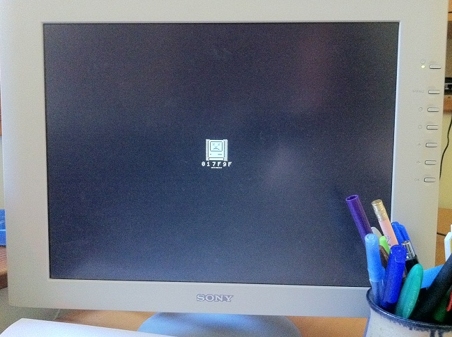
Things are starting to warm up now. I’ve successfully booted Plus Too as far as the Happy Mac startup icon! It’s not booting all the way into the Finder yet, but most of the tricky business with the IWM, floppy, and disk encoding schemes has been proven to work. Hooray!
If you can tolerate some shakey-cam video, here’s a movie that demonstrates Plus Too’s current capabilities. It shows booting to the question-mark disk screen, moving the mouse, inserting a blank disk, ejecting a disk, inserting a fragment of a System 3.3 startup disk, and the Happy Mac.
I’ve divided all of Plus Too’s disk-related functions into three parts: IWM, drive, and disk. The IWM is the floppy disk controller chip in the classic Macintosh, and my model of the IWM is finished and working. The Plus Too drive model replicates the brains of a 3.5 inch Sony floppy drive, which has sixteen 1-bit status and control registers. The drive model is mostly done, but there are still a few functions related to disk swapping and disk writing that are incomplete. The disk model replicates the GCR encoded data format of a 3.5 inch Macintosh disk, and is where more work is needed in order to boot to the Finder.
Plus Too is intended to load 400K/800K disk images from an SD card, perform on-the-fly GCR encoding for each sector, and pass the result to the drive model and IWM. That part isn’t working yet, so I took some shortcuts in the test shown in the video. The GCR encoding was done offline with a Windows PC, using a custom program I wrote. Then five sectors of the encoded data were stored in a block ROM inside the FPGA itself. Five sectors isn’t much, but it’s all I had space for, and it’s enough for the Mac to recognize a boot disk and show the Happy Mac icon. Testing the boot sequence this way enabled me to confirm that the GCR encoding algorithm is correct, and that the IWM and drive models are working, even before the SD card interface and on-the-fly encoding module is ready.
Next Steps
The next logical step is to implement an SD card reader interface, so I can load encoded data from the card instead of from the limited FPGA memory. Once that’s done, I should be able to boot all the way to a working Finder. For a read-only system I technically don’t need to do any more than that, but doing the encoding on the fly instead of with an offline tool would be much nicer. To support disk writes, on-the-fly encoding (and decoding) will be a necessity. The encoding and decoding algorithm is somewhat complex, and I’m unsure whether to attempt to design a Verilog state machine to do it, or incorporate a simple microcontroller core (maybe even Tiny CPU) and do it with a conventional program instead.
Other Concerns
There are all kinds of timing problems and glitches hiding just beneath the surface, and I’m worried. Every now and then I’ll make a change that causes Plus Too to exhibit broken behavior or fail to boot, even some innocuous change that definitely doesn’t affect the logic. Just today I made a change that caused an unexplained boot failure, and in the latest version I get random mouse droppings when the mouse is in a certain area of the screen.
Usually if I rearrange some modules or make some other superficial change, the problem will disappear, but that’s a very scary situation. There’s no doubt I need to master the Altera timing constraints editor to sort it all out, but my earlier attempts to make sense of it were dismal failures. Unfortunately, it doesn’t seem to be possible to translate a statement like “external signals D15-D0 must be valid no more than 50ns after the clock edge” into a simple constraint that I can enter somewhere. The whole system seems geared toward me writing custom Tcl scripts, which so far I’ve refused to do. Reading through the documentation, my eyes quickly glaze over and I wonder again why this all has to be so complicated.
A few concerns remain in the drive subsystem as well. With my current test setup, I always return the same five sectors of data, regardless of what track or side is actually being accessed. It’s possible there’s some hidden complexity there that I’ll need to address, or that I’ll incorrectly map disk image data to the wrong sectors, or that the method I’m using to determine what track and sector is being accessed isn’t even valid. This is a fairly small detail, though, and I’m optimistic I’ll be able to extend the current model to support all tracks and sides without major problems.
Read 7 comments and join the conversationCrazy Disk Encoding Schemes
Wow. I expected the details of the Macintosh floppy data encoding to be a bit complex, but this is worse than I expected. I think I finally understand it well enough to duplicate it, but I can’t explain why it does what it does. Maybe whoever extended Woz’s code from the Apple II was just in a bad mood.
I’ve been focusing my attention on how a single sector’s data is represented on the disk. Most of it is fairly easy to understand, once you’ve found a reference. Each sector consists of an address block and a data block. Between the blocks are $FF sync bytes. The address block begins with a specific header ($D5AA96, a sort of secret password for old Apple II hackers), then five encoded bytes containing the disk format, track number, sector number, and a checksum, and ends with a specific trailer sequence. The data block begins with a different header, then the sector number, the encoded sector data, and a trailer sequence.
It’s the “encoded data” step where things start to get tricky. Logical data bytes must be encoded into disk data bytes before being written to disk. This is due to physical limitations of the magnetic disk media: bytes with too many consecutive zero bits can not be stored reliably. Of the 256 possible bytes values, only 64 (or is it 67?) values can be stored on disk reliably, so the Mac encodes six bits of logical data at a time into one of the 64 “safe” disk byte values, in a process called 6-and-2 GCR encoding. There’s a 64-entry table in the Macintosh ROM for converting six bits of logical data into the corresponding disk byte, which was often called a nibble (even though it’s not 4 bits). When reading a sector, the process is applied in reverse.
All of this I more-or-less already knew before I began. I expected to find a routine somewhere in ROM that grabs three logical data bytes at a time (24 bits), and shifts out six bits at a time, using the GCR lookup table to produce four disk bytes. Once I found the disk sector write routine, it became clear it does more than that. My first hint was this French page about Apple II DOS 3.3, whose low-level disk format is very similar to the Mac’s. According to this page, data values aren’t used directly as indexes into the GCR table. Instead, each data byte is XOR’d with the previous byte, and the result is used as the index into the GCR table. Why? This is where I fail, because I have no idea why. It seems somehow related to checksumming the data, but it would be easier to use the data values as direct GCR table indexes, and then use the sum of all data values as a checksum.
An unexplained running XOR-based index is strange, but I could live with that if it were the only unexplained part. Unfortunately it seems that either the French page is incomplete, or else the Mac encoding method is more complex than Apple DOS 3.3 encoding. I’ve stared at the 68000 assembly code in the ROM routine for quite a while, as well as C re-implementations from MESS and from Ben Herrenschmidt, trying to grasp some kind of high-level purpose in it, but it just seems arbitrary to me.
Instead of XOR-ing each value with the previous one, it XOR’s each value with the sum of all previous values back to the beginning with a stride of three. For example, the 10th value is XOR’d with the sum of the 9th, 6th, 3rd, and 0th values. To facilitate this, three running sums are maintained for the values on the 0th, 1st, and 2nd stride. But wait, it’s more complicated than that. After every 3 logical bytes, the sum for stride 2 is rotated left one bit position, and the bit that’s rotated out is added into the 0th stride sum, and any overflow there is added into the 1st stride sum, whose overflow is added to the second. Or something like that. It’s all a little crazy.
Read 12 comments and join the conversationMac Floppy Disk Hardware
Ugh, I’ve been going around in circles trying to settle on the best way to add a floppy disk replica to Plus Too. I’ve been thinking about this way too much, and now I’ve got visions of sync bytes dancing in my head. Here are the two main options:
Replacement Disk Driver
I could create a new disk driver that replaces the one in the Mac’s ROM. The great thing about this approach is that the driver API is very straightforward: it receives requests to read/write X bytes from offset Y on the disk. This could be almost trivially mapped to a disk image in a separate ROM or on a SD card, without ever having to worry about the IWM, disk heads, tracks, sectors, encodings, sync bytes, or anything else. A custom driver would also make it possible to have more disk drives, and larger disk sizes that don’t correspond to any real floppy disk.
The big drawback of this approach is that writing a custom device driver isn’t easy! Unfortunately it’s not as simple as just processing those read/write requests. The driver must correctly handle synchronous and asynchronous calls, hook into the interrupt manager, and handle all manner of control and status requests in the same way as the original Sony floppy driver. I’ve spent a substantial amount of time digging through the internals of the Sony driver, and it’s pretty complicated. I don’t think I’m really up for the challenge of writing a new driver in 68000 assembly, using MPW. Even if I did get something that mostly worked, it’s likely the kind of thing that would have subtle bugs that would cause all kinds of hard-to-find problems.
A secondary concern is how to actually replace the original disk driver. I could modify the ROM image before programming it to the ROM chip, but that seems a little heavy-handed, and would make it more difficult to support a multi-Mac replica that handles more than one original ROM type. It would be nicer if the replacement driver were overlaid onto the Mac’s memory map without physically modifying the original ROM. But where would the replacement driver code be stored– in some other ROM? Or in internal memory of the FPGA? This could be solved, but it feels yucky.
IWM and Floppy Replication
The alternative approach is to use the original ROM floppy driver, and make hardware to replicate the behavior of the IWM and floppy drive. This was my original plan, and after a detour to examine the replacement driver idea, I think I’m going to return to this one. The big advtange of this approach is that success or failure will be binary: it won’t work at all, until it works 100%. That’s a lot more appealing than endless chasing bugs in a custom driver. This approach doesn’t require any ROM patching, and would also be a good foundation for later building the external floppy emulator for real Macs that I’ve been talking about.
This method does have several drawbacks. Replicating all the behaviors of the IWM and the floppy won’t be easy, especially the floppy behaviors. I’ve more or less mapped out everything I need to know to do it, but it’s still going to be a large task. This method also limits Plus Too to two* 800K disks, just like a real Mac Plus. I’m also concerned about implementing disk writes with this method: when the IWM starts spitting random bytes at the disk interface, it will take some processing to work backwards and figure out what sectors the Mac was actually trying to update.
Neither approach really seems great, and both would be a substantial amount of work. My gut tells me that IWM and floppy replication is a big task I can succeed at, whereas a replacement disk driver is a big task with a high potential to veer off into a ditch and fail, but maybe I’m overly pessimistic. Here’s hoping I can get at least one of these approaches to work!
* all three homonyms of “to”, consecutively in a sentence… English is crazy!
Read 6 comments and join the conversationMac Toolbox Mysteries
I’m making slow progress on Plus Too, unraveling the mysteries of the Mac’s operation little by little. I haven’t really worked on the IWM and floppy components yet, because I’ve been consumed with chasing down other details, and trying to learn how to create FPGA timing constraints. There has been some visible progress, though: you can now move the mouse cursor around the question-mark disk screen, and the question mark flashes on and off. Woo-hoo!
In order to learn why my hardware doesn’t work as expected, I usually have to disassemble and examine the portions of the Toolbox ROM routines that access the hardware, so I can understand how it’s supposed to work. This has been a slow and painful task, one I’d compare to swimming through mud. Certain parts of the ROM routines are beginning to make sense to me now, though, and I’ve discovered several “mysteries” in the routines that are either vintage Apple bugs, or else places where my understanding is flawed.
Broken Timers
The Macintosh VIA’s Timer 2 is configured as a one-shot 16-bit countdown timer. When the countdown reaches zero, the VIA triggers an interrupt. Because the VIA runs at 783.36 kHz, the maximum possible timeout delay = 65536 / 783360, or 84 milliseconds. To implement delays longer than that, the ROM routines repeatedly schedule T2 for successive 84 millisecond delays. Here’s a portion of the relevant code from the Toolbox ROM:
P700:
           Tst.L     D1               ; D1 is a pointer to the timer parameters
           BEQ       L3640
           Move.L    D1, A1
           Move.L    $A(A1), D1       ; get the desired timeout delay (in milliseconds)
           MoveQ.L   $54, D0
           Cmp.L     D0, D1
           BLE       L3639            ; if the desired delay is more than 84 ms, then just do 84 ms
           Move.L    D0, D1
L3639:     Move.L    (TimeVars), A1
           Move.L    D1, (A1)         ; save the actual delay value
           MulU      $30C, D1         ; convert milliseconds to VIA clock cycles
           Move.L    (VIA), A1
           ROR       $8, D1
           Move.B    D1, $1200(A1)    ; store high byte of delay in T2C-H
           ROR       $8, D1
           Move.B    D1, $1000(A1)    ; store low byte of delay in T2C-L
           Move.B    $-60, $1C00(A1)  ; enable the timer 2 timeout interrupt
           Lea.L     P_VIAInt5_Timer2, A0
           Move.L    A0, (Lvl1DT.5)   ; install the interrupt handler
L3640:     Rts
The important thing to notice here is that the high byte of the timer is loaded before the low byte. According to the VIA 6522 datasheet, this is wrong, and will generate incorrect timeouts. The datasheet explains that T2C-L (the low byte of the T2 counter) can not be directly written. Instead, a write to that register will write to a latch called T2L-L. Then when T2C-H is written, the VIA will simultaneously load T2C-L from T2L-L, and arm the timer. By writing the timer bytes in the opposite of the expected order, this ROM routine will end up using whatever low byte was intended for the previous invocation of T2, resulting in a timing error of up to 0.33 milliseconds. Probably no one attempts to use the timer for sub-millisecond timing, so the bug isn’t noticed in practice.
Question Mark Flash Rate
The question mark at the boot screen flashes on and off. I would have guessed that the flashing rate was governed by a timer, but apparently it’s just a hard-coded delay loop.
      MoveQ.L   $4, D0
      Swap      D0
L70:  SubQ      $1, D0
      BNE       L70
Because my TG68 soft-CPU requires fewer clock cycles per instruction than a real 68000, this loop runs faster, and the question mark flashes about 2-3 times the normal rate. It makes Plus Too look a little hyperactive. This could cause different behaviors on real Mac hardware as well. I’m not sure if this same ROM routine is used on the Mac II, but if it is, I would expect the question mark to flash faster than on a Plus, due to the faster CPU.
There’s another point about this code snippet that I don’t understand: D0 is initialzed to the long value $00000004, then the lower and upper halves are swapped, which changes the value to $00040000. But the loop performs a SubQ, not a SubQ.L, so only the lower 16 bits of D0 are used in the subtraction. That means the initial value of 4 is irrelevant, and the loop will execute 2^16 or 65536 times.
Mouse Button at the Question Mark Screen
Apparently if you hold down the mouse button while the Mac is at the question mark disk screen, it does… something. I discovered this by accident, because at first my mouse adapter behaved as if the button were always pressed. Try this on a real Mac Plus! It makes some seeking noises from the floppy drive, about once every second, as long as you hold down the mouse button. From a look at the ROM routines, it seems like it tries to force the Mac to read the disk, even if it doesn’t think there’s a disk inserted. Anyone know for sure what this feature is for?
Flickering Mouse Cursor
After I got the mouse movement working, one of the first things I noticed was that the cursor flickers when it’s in the bottom third of the screen. I assumed this was a problem with my hardware design, and spent quite a while trying to discover the root cause. After a lot of digging, I found that every time the question mark flashes on and off, the ROM routines call PlotDisk to draw and erase it, whose code looks like this:
P_mPlotDisk:
      _HideCursor
      Move.L    (Ticks), D0
L72:  Cmp.L     (Ticks), D0
      BEQ       L72	; wait until Ticks has changed
      ; ... disk icon drawing code is here
L73:  _ShowCursor
      Rts
First it hides the cursor, then it waits until Ticks has changed, which indicates that the VBlank interrupt routine has run. This looks like an attempt to ensure the disk icon drawing code happens during VBlank to avoid flicker, but it’s flawed. It could take up to a full 1/60th of a second for Ticks to change. During the time the routine is waiting for the change, the cursor has already been hidden. If the screen area containing the mouse is repainted during this time, the user will see cursor flicker. To fix the bug, the call to _HideCursor should be moved to after the wait loop, and just before the actual disk icon drawing code.
My moment of triumph came when I tried this on a real Mac 512Ke, and observed the same cursor flickering behavior. If the cursor is moved to the bottom portion of the screen, it will flicker every time the question mark flashes on and off. I’ve managed to reproduce the exact behavior of an obscure, timing dependent bug from the real Mac hardware. Try that, software emulators!
Read 7 comments and join the conversationQuestion Mark Disk
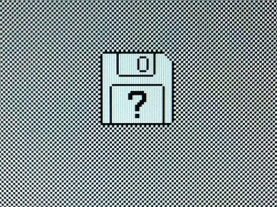
Now I’m really getting somewhere with Plus Too: it’s the “question mark disk” screen! If you ever owned a Macintosh with no hard drive, you’ll be very familiar with this screen, because it was shown whenever the computer was turned on. It’s the Mac’s way of saying “please insert a system disk.” It means everything is OK, ready to go, but it needs an operating system disk to proceed further. Here’s another photo, this time showing the entire screen:
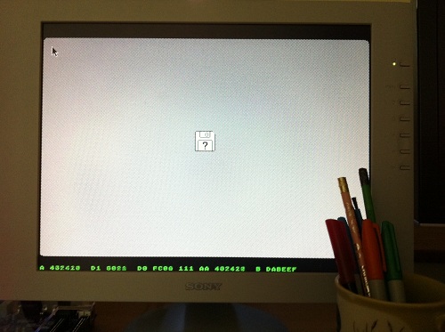
The mouse pointer appears in the upper-left. With a bit more work, I should be able to move the mouse around while on this screen.
The green text at the bottom of the screen is my primitive on-screen debug interface. Because the pixel-doubled 512 x 342 Mac desktop is only 684 pixels tall, there’s some extra space above and below it when running at 1024 x 768 SVGA resolution, and it’s the perfect place to show debug data. The green text isn’t drawn by the Mac (which after all can only do black and white), but by the video output circuit in the FPGA. There are effectively two video sources which it combines: one from the Mac screen buffer, and one from the debug interface. The debug text shows the current CPU address, data in, data out, address strobe, data strobes, previous address, and breakpoint address. The breakpoint address can be modified by setting the positions of switches on the Altera DE1 board, and pressing a button to load the low, middle, or high byte of the address. Crude, but it’s better than nothing.
Thus far I’ve actually implemented very little Mac-specific hardware behavior, so it’s suprising that it gets to the question mark disk screen. The implemented hardware is:
- 68000 CPU (synthetic soft-CPU in the FPGA)
- 128 KB ROM from Mac Plus (in external Flash ROM)
- 512 KB RAM (in external SRAM)
- address decoder maps ROM to $400000 and RAM to $000000
- IWM floppy controller always returns $1F when read, and otherwise does nothing
- Reads from address $FFFFFx return 24 + x. This makes interrupt vectors work correctly.
- VIA is partially implemented: vblank and one second interrupts work, the interrupt enable and flags registers work, and the memory overlay bit works.
- Video circuit reads from a hard-coded frame buffer address of $3FA700, which wraps around to the correct address in the 512 KB RAM space.
That’s it. There’s nothing whatsoever for the keyboard, mouse, disk, sound, or SCC, and the VIA is only about 25% implemented. I did have to cheat a little to reach the question mark disk screen: there’s still something wrong with my interrupt flags, and I had to flip a switch a few times to manually enable and disable interrupts. Without my intervention, it stalls indefinitely on a black screen. Hopefully the interrupt problem will be simple to fix.
Reaching the question mark disk screen is great, but it’s sobering to realize that getting further will probably require an order of magnitude more work than I’ve done so far. That’s because it will require implementing the IWM behavior, as well as the behavior of the floppy drive itself, and the lowest-level bit-by-bit data representation on a floppy disk. On the other hand, once I do get past this screen, I should be most of the way to having a working Mac clone.
Read 9 comments and join the conversation
Sad Mac

I’m working with my Xilinx Spartan 3A FPGA board for the moment, and I’ve finally made some visible progress. I’ve never been so happy to see a Sad Mac! A boot failure may not seem very exciting, but I’m thrilled that it’s actually doing something recognizably Macintosh-like. That means it’s actually running 68000 code from the Mac ROM, which is drawing stuff to the screen buffer, which is getting read by the video module and displayed to the VGA screen. From here it will be a long, slow road of implementing replacements for the VIA, SCC, IWM, and other components.
Using a FPGA dev board for initial development makes it much easier to get started than it would be with a pile of discrete ICs. All the other “hardware” is actually synthesized inside the FPGA: a 68000 soft-CPU (TG68 core from opencores.org), 32K RAM, and 8K ROM. The synthetic RAM/ROM sizes are much too small for a Macintosh, but are all that would fit inside the FPGA. They’re enough to create a screen buffer and run the initial boot code from ROM, anyway.
I have an Altera DE1 dev board on the way, which has real external SRAM and Flash ROM that I can use instead of the synthetic RAM/ROM. (The Spartan 3A board has DDR RAM that I could never figure out, and ROM that can only be programmed through a serial port.) I haven’t yet decided whether to add a real 68000 to the DE1 on an expansion card, but given how easy it was to get the TG68 soft-CPU working, I’ll probably stick with that.
Eventually I’ll need to construct an expansion card for the Altera DE1 board, containing a microcontroller and some other things, but I should be able to get pretty far with just the DE1. The DE1 is an “educational” board with all kinds of miscellaneous gizmos. My long-term goal is to make an all-custom Plus Too board that contains only the parts actually needed, as well as vintage connectors for a Mac keyboard, mouse, and floppy.
The Sad Mac is appearing because the ROM checksum test failed. That’s not surprising, considering I only implemented the first 8K of the 128K ROM. It’s trying to play a sound, too, by streaming some data through the sound buffer. With some more work to pull bytes from that buffer at 22 KHz, I could hear the glorious boot beep!