

Small-Scale Solar Experiments
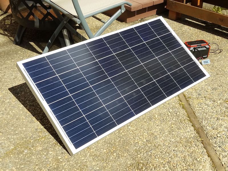
While sheltering in place this week, I’ve been tinkering with a small-scale setup for solar power generation. I’ve got a 100 watt solar panel, and access to the sun. What fun things can I do with this? Is it actually useful? Let’s find out.
My first thought was to power some equipment directly from the panel, but that’s not practical for most situations. Even if I could tolerate only having power during daylight hours, the output voltage and available power from a solar panel fluctuates too much from moment to moment. I’d either need a DC-to-DC voltage converter with a wide input range, or some equipment like a pump that can tolerate a wide voltage range and doesn’t mind frequent stopping and starting.
For most purposes it’s better to charge a battery from a solar panel, and then use the battery to power other equipment. I already have a solar generator (a large battery with integrated charger, inverter, and other conveniences) that was ideal for this experiment. I only needed to connect the panel’s MC4 output to the solar generator’s MC4 input adapter cable, stick it in sunlight, and wait.
100 Watts? Not So Much
With a 100 watt panel and something close to 12 hours of daily sunlight, I expected to get something close to 1200 watt-hours of electric production daily. My solar generator has a 150 Wh battery, so it should only take about 1.5 or 2 hours to charge. So I confidently set up the equipment, and after an entire day in the sun I only managed to increase the battery level by about 40%. What?
Maybe 1200 Wh was a little unrealistic. Or a LOT unrealistic. After some reading, I concluded the panel would probably never output 100W unless it was noon on a bright sunny day somewhere near the equator. But I might hope to get about 70W at noon at my latitude, with lower power output during the morning and late afternoon. Factoring in shadows from trees and other buildings, I decided I might expect to get about 400 Wh of average total daily production, with more in summer and less in winter.
OK then, 400 Wh should still be enough to charge my solar generator’s battery almost three times during the course of a day. So why wasn’t I getting that result?
Measuring Solar Panel Output
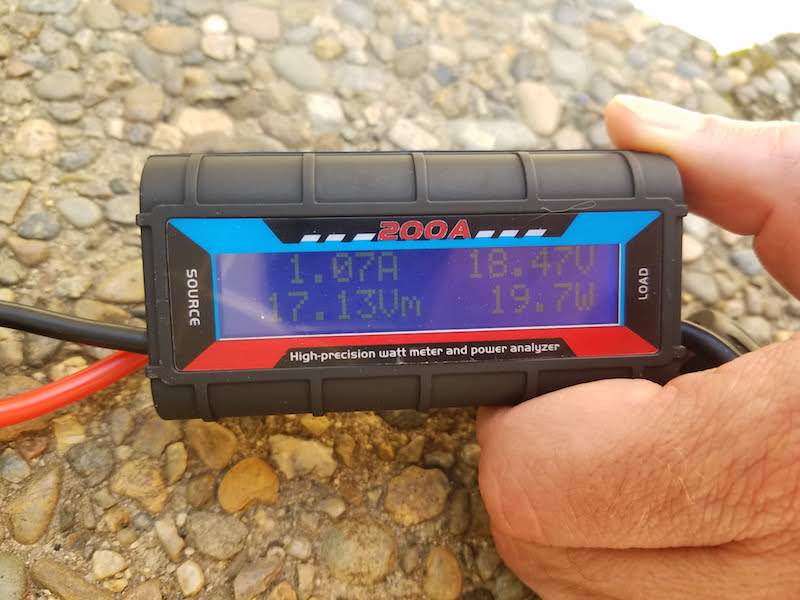
It’s not so easy to measure the power generated by a solar panel. With a multimeter I could measure the open circuit voltage, and the short circuit current, but multiplying the two figures wouldn’t tell me the power. I need a load to get a useful measurement for power output. But a fixed resistive load won’t work, not even a 100W-rated resistor, because it likely won’t bring the solar panel to the correct voltage for optimum operation. That optimum voltage varies from moment to moment, based on the sunlight hitting the panel. To do this right, I needed a solar charger like the one integrated into my solar generator. Then I needed to measure the current and the voltage simultaneously. I could have built some wiring adapters and used two meters for the measurements, but instead I bought a cheap inline power meter and soldered MC4 connectors to it.
I measured 19.7W in full sun at noon. Huh?! No wonder the solar generator’s 150 Wh battery takes forever to charge. Is there something wrong with my panel? After several days of tinkering with the setup under different lighting conditions, I never saw a continuous output higher than 23W. Most of the time it hovered right around 20W. Hmm.
I began to suspect the solar generator was at fault. Sure enough, buried in the manual were the specs for the solar input: 13V-22V / 2A max. With my solar panel, that means I’m theoretically limited to about 40W max (2A at almost 20V). I’m not sure why I rarely saw more than 20W though, and never saw more than about 1.3A of current. Maybe the integrated solar charger is even more limited than the manual suggests? Maybe I have bad wiring, or another problem?
As an engineer, 20W from this panel is insulting! Even if I have no practical need for this solar panel, losing 80% of its output is unacceptable to me. To save my pride I’ve begun to research plan B, which will involve a stand-alone solar charge controller featuring a much higher maximum charging rate, and a separate battery. More about that soon. Maybe I’ll put together a solar-powered Mac Plus.
Finding the Parts
Some links below may be affiliate links. BMOW may get paid if you buy something or take an action after clicking one of these. As an Amazon Associate BMOW earns from qualifying purchases.
Here’s the equipment I used.
Renogy 100W monocrystalline solar panel. You can find slightly cheaper panels, but the Renogy has an extra-sturdy aluminum frame and a strong reputation for quality. This particular panel is also more space-efficient than most other 100W panels, if minimizing area and weight are important to you.
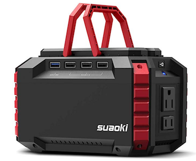
Suaoki 150Wh portable power station. Despite its annoying 2A charge rate limitation, I love this thing and use it all the time. You can charge it from solar, from a car, or from a wall plug. It has a built-in 100W inverter for running small appliances, USB ports (including a Quickcharge 3.0 port) for charging phones and tablets, 12V ports for DC lights and other appliances, and an integrated high-brightness emergency lamp.
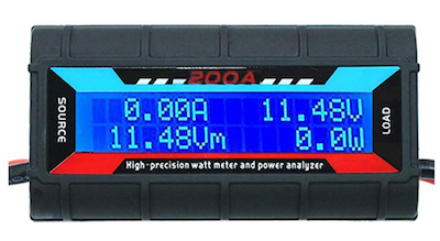
200A Inline Watt Meter. I’m not confident it will actually handle 200A, but it works nicely for lower currents involved in small-scale solar. It shows volts, amps, watts, accumulated amp-hours, watt-hours, max watts, and min volts.
MC4 Male/Female Solar Panel Cable Connectors. Solder these to the watt meter.
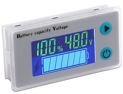
DROK 12V Battery Meter with adjustable limits. Other cheap battery meters typically have fixed voltages for the 100% and 0% charge state. This one makes it possible to set custom values for the upper and lower bounds. Measured from one of the Suaoki’s 12V ports, I measured 12.33V fully charged and 8.96V just before the low-voltage cutoff disconnected the battery. The discharge curve isn’t linear, so the meter won’t go smoothly from 100% to 0%, but this is still vastly better than the simple built-in 5-bar power gauge on the Suaoki.
Read 16 comments and join the conversationConstant Power Battery Discharge
Recently I’ve been looking at battery datasheets, in preparation for an off-grid solar project. I’ve noticed something strange about the “constant power discharge” numbers in the datasheets of several 12V lead acid batteries. Here’s an example from a 20 Ah Euroglobe sealed lead acid battery.
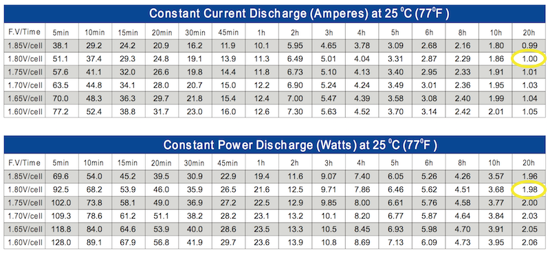
In the Constant Current Discharge table, if you discharge to a final voltage of 1.80V/cell (10.8V total voltage), the entry circled in yellow shows that you can get a current of 1.00 amps over 20 hours. The voltage will drop from around 13V down to 10.8V during that time. Let’s call it an average of 12V times 1A – that means you can average about 12 watts for 20 hours.
But wait. In the Constant Power Discharge table, if you discharge to a final voltage of 1.80V/cell over 20 hours, the entry circled in yellow shows a power of just 1.98 watts. That’s far less than 12 watts. Why?
Other table entries show something similar. It’s 11.3 amps constant current for 1 hour – that should be an average rate of about 136 watts, but the Constant Power Discharge table shows a measly 21.6 watts. It’s not just this particular battery either. Here’s a 35 Ah lead acid Mighty Max battery that shows the same curious pattern in the Constant Power Discharge table.
So what’s going on here? Am I misunderstanding what these tables mean? Or is there some other factor that limits the power to a much lower number than is suggested by the constant current data? I’ll keep digging for answers.
Read 5 comments and join the conversationShelter In Place

My family and I have been ordered to shelter at home until at least April 7, to help stop transmission of COVID-19 in the San Francisco area. Many of you may already be living under similar orders, or will be shortly. Travel is restricted to only the “most essential needs” – basically food and health care.
As you can imagine, this will severely impact business shipments. BMOW will still be accepting new orders during this time, but it will likely be impossible to ship anything until April 7 or later. Please be patient, and if you’re not prepared to wait at least 3-4 weeks for delivery, then please hold off until mid-April to place your order.
Stay safe everyone. Remember to wash your hands.
Read 7 comments and join the conversationBackyard Metal Foundry Dreams

Sometimes my brain works in unexpected ways. I haven’t started any new electronics projects lately, but my thoughts have been spinning in other directions.
Last weekend I jokingly told my kids that I was starting a home-based ore smelting business. Because today’s busy families just don’t have time to process their bauxite, taconite, and other ores at home, the way Grandma used to. Keeping up with the household’s demand for antimony and zinc can be such a chore – but now there’s a better way! My friendly staff will pick up your ore, lovingly smelt it, dispose of the slag responsibly, and return the processed metal in 100g nuggets stamped with your choice of fun logo designs. Naturally, this ore smelting business will be named He Who Smelt It Dealt It.
Three things I learned from this groan-worthy joke:
- It’s taconite, not taco night
- I’ve been pronouncing the word antimony (an·tuh·mow·nee) wrong for my entire life
- Melting converts a solid into a liquid. Smelting converts ore to its purest form.
Yet somehow this smelting comedy gradually transformed from a bad joke into a semi-serious idea for a fun backyard project. Actual smelting probably isn’t a great plan, because where the heck would I find ore? And do I really want to process large piles of messy rocks to extract a bit of tin? Instead of smelting, I soon found myself researching designs for a backyard metal foundry.
I was fascinated. This Mini Metal Foundry design looks simple to build and operate, but can easily reach temperatures of 660 C (1221F) – hot enough to melt aluminum, zinc, lead, tin, and pewter. The molten metal can then be poured into steel molds or sand cast to make tools, toys, and trinkets. Sure the quality won’t be great, but if you perked up at hearing the words “molten metal”, then I like your thinking and we should hang out sometime. Check out this video:
Of course I immediately began planning for my backyard metal foundry. My wife, however, was considerably less enthusiastic about my prospects for doing this without making the neighbors call the fire department or outright killing myself. She has an advanced degree in materials science, and actually has real lab experience working with large pools of molten lead, germanium, and other metals, so she probably knows what she’s talking about. I began to pay more attention once I learned about what happens if there’s a metal spill onto outdoor concrete. Moisture held in the concrete can instantly flash into steam, shooting globs of molten metal in all directions at high speed. See the example at time index 7:35 in the video. It looks horrific. So I’ll hold my backyard foundry plans in the “maybe” category for now.
Enter plan B, an inexpensive 500 Watt electric ladle. Designed for small metal casting projects, this little gem can’t melt aluminum, but it’s still hot enough to melt lead and maybe zinc (though I’m not sure exactly what I’d do with molten zinc). For about $50, it could be the perfect tool for DIY-enthusiasts who want to melt some metals without burning down the house.
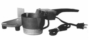
A few metals that might pair nicely with this tool, ordered by melting point:
zinc (maybe) – 419C, 787F – The tool says it’ll melt lead, but the melting point of zinc is not too much higher. What can you do with zinc? I’ve heard of zinc plating, but don’t think I’ve ever seen a solid zinc object.
lead – 327C, 621F – Lead has a bad reputation these days, but how great is the risk assuming you’re not eating the stuff? Maybe it’s best to avoid it anyway.
pewter – 295C, 563F – In my mind, pewter is what 18th century candlesticks are made from. It’s an alloy of tin, antimony, and copper. It’s also sometimes used for jewelry and can be polished to a shiny finish.
bismuth – 271C, 521F – I have no mental concept of bismuth except as an ingredient of Pepto-Bismol. What does metallic bismuth look like? Is it safe to handle? Is it ever used for metal casting?
babbitt – 249C, 480F – I’m including babbitt on this list because I’d never even heard of it until yesterday. I learned that babbitt is an alloy of tin, lead, copper, and antimony, and is commonly used for making low-friction bearings.
tin – 232C, 449F – In years past, tin was popular for making cups and dishes. It should be cheap and safe, but maybe not very exciting. At this melting point, I wouldn’t even need any special heating tools: I could just melt tin ingots in steel molds with my kitchen oven.
solder – 183C, 361F – Solder wouldn’t normally be used for casting, but why not? Probably because it’s too easily bendable, and there are better alternatives. Lead-free solder has a higher melting point of 217C/422F, but it’s still lower than any other metal on this list.
Why do all the metals with low melting points have a silver/gray color? It would be nice to have more variety. To find a metal that’s a difficult color, I believe you have to climb the temperature scale to about 890C/1630F to melt brass and bronze. Copper and gold have melting points that are even higher. If I were a super chemist, I’d probably have some explanation why metal colors are related to their melting points.
Have you ever experimented with metal casting for making jewelry or tools? Ever built a backyard foundry and melted some aluminum soda cans? Leave a note in the comments and tell us your story.
Read 13 comments and join the conversation
BMOW Store Trouble
Yesterday’s upgrade to PHP 7.1 has broken the BMOW store checkout process. You can add items to your cart and authorize your payment, but the final “confirm payment” step leads to a blank screen. The payment never gets processed, and the items remain in the shopping cart. Please bear with me while I sort this out… UPDATE: It’s working now.
Read 2 comments and join the conversationFloppy Emu SoftSP Warning
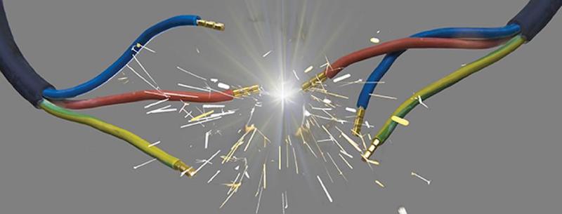
I’m calling attention to a hardware issue with the third-party “softSP” card that can damage your Floppy Emu when the two are used with a Disk II controller card in an Apple II+ or Apple IIe. This issue creates a power-to-ground short circuit that will cause accumulating damage to the transistor structures on Floppy Emu’s interface chip. The symptoms don’t appear immediately, and it may seem that everything’s OK for days or weeks, until the Floppy Emu begins to fail irreversibly. The good news is that a simple cable modification is all that’s needed to use softSP and Floppy Emu together safely.
softSP Pseudo-Smartport
BMOW isn’t affiliated with the softSP card – it’s sold by a third party and is designed for use with another type of disk emulation product. It does appear to work with the Floppy Emu initially, and in recent months the Total Replay game collection has inspired a few people into using softSP with the Floppy Emu. Some popular YouTube videos even specifically recommend this combination, even though softSP isn’t designed for use with the Floppy Emu.
The problem is that softSP provides a software patch for Apple II disk controller functions, but does nothing to address the resulting low-level electrical problems on the disk interface. The softSP card contains a small ROM that overrides the built-in ROM on a standard Disk II controller card. It essentially reprograms the Disk II card, so instead of functioning as a 5.25 inch floppy disk controller, it now functions like a Smartport disk controller, which supports block-based disk I/O for disk sizes up to 32 MB. Neat! But there’s a catch.
You can’t safely connect a Smartport device to a Disk II controller card, no matter how the card’s internal logic might be modified. That includes Floppy Emu when it’s configured in Smartport emulation mode. The reason is that Smartport devices connect pin 12 internally to ground. This is how other connected equipment and daisy-chained drives know that they’re Smartport drives, and it’s essential for correct daisy-chain operation of Smartport drives with the BMOW Daisy Chainer or the Apple Unidisk 3.5 drive. For other types of Apple II disks as well as the Macintosh and Lisa, pin 12 is used for the SELECT signal. But on the Disk II controller card, pin 12 is connected to the +5 volt power supply. So when you connect a Smartport device to a Disk II controller, you create a direct power-to-ground short circuit. Ouch!
To be clear, there’s no specific hardware problem with the softSP card itself – it’s just a ROM. The problem arises when using the softSP card to reprogram a Disk II controller card, which is then connected to a Floppy Emu that’s configured in Smartport emulation mode.
Accumulating Chip Damage
The Floppy Emu board has a small inline protection resistor that will prevent immediate damage and failure due to this short circuit, but it’s only meant to protect against brief transients during power-up and power-down, or brief accidental mis-configuration. The Floppy Emu’s CPLD interface chip will likely not survive sustained operation in this mode, because it will cause a continuous current on pin 12 due to the short circuit, with a current level that’s more than twice the absolute maximum rating of the chip. This can eventually cause damage to the chip that will appear as intermittent disk errors or total failure of the device. Unfortunately this type of damage is cumulative, so even if you stop using Smartport mode with softSP and a Disk II card, the damage is already done.
With the continuous over-current, the insulating silicon layers between parts of a transistor can wear away, or develop small holes. At first the effect is minor – maybe the leakage current is more than it should be, or the noise margins are reduced below the spec. The chip may still work OK under normal conditions, but problems may appear under extraordinary conditions at high/low temperatures, or when the supply or signal voltages are close to the rated margins, or when substantial EM noise or voltage transients are present. A problem might cause a 0 to become a 1 somewhere, resulting in a visible I/O error, or it might cause the whole chip to stop functioning until power is turned off. As chip wear grows worse, you may start to see these kinds of problems during ordinary usage. Eventually the problems will grow so frequent that the chip is no longer really usable, or the wear will progress all the way to an internal short-circuit or open circuit within the chip itself, effectively destroying it.
This kind of chip damage can be viewed as a type of gradual wear, like wearing down the engine in your car, rather than a simple yes/no question of is it damaged or not-damaged. Even normal use causes chip wear, and chips do have finite lifetimes, but normally the lifetime is measured in decades or longer. In this case the power-to-ground short circuit is like driving your car without enough oil in the engine. It’ll work for a while, but you’ll start to notice it’s running increasingly rough, and maybe it’ll develop occasional trouble with stalls or failure to start. Then one day the engine will completely seize up and the car will no longer run at all.
Cable Modification Fix
A simple work-around is to sever the 12th wire of the 20-conductor ribbon cable. The red wire is number 1, so simply count wires from there and cut number 12 using a small nail or a razor blade. The resulting cable will work for softSP Smartport emulation with a Disk II controller card, without creating a power-to-ground short circuit. It will also work for standard Apple II 5.25 inch floppy disk emulation. But the modified cable won’t work for true Smartport emulation with other Smartport hardware, nor for 3.5 inch floppy disk emulation, nor for Macintosh or Lisa disk emulation. If you don’t want to modify your original ribbon cable, you can get a spare cable from DigiKey for a few dollars.
Unfortunately modifying the cable won’t undo any damage that’s already been done, so if you plan to use softSP with your Floppy Emu, you’ll need to make this cable modification right from the start. Be safe!
Read 14 comments and join the conversation