Adventures in Microcontroller Circuit Debugging

How do you go about troubleshooting a misbehaving microcontroller circuit? A few months ago I manufactured a new batch of Floppy Emu disk emulators. A number of them failed QA at the factory, with a set of symptoms that I’d never seen before in all my years of developing this device:
- Most of them simply wouldn’t boot up at all, despite verifying that power was good and the mcu was correctly programmed.
- Some exhibited “haunted” behavior, seemingly jumping to random sections of the mcu program code, outputting messages on the display that made no sense given the context.
- One of them appeared to work in slow motion, with LED blinking and display updates noticeably more sluggish than normal.
This was odd, to say the least. I have a lot of experience with the ATMEGA1284 microcontroller and the Floppy Emu circuitry that surrounds it, and I’ve become an expert at guessing what’s wrong based on the symptoms of misbehaving boards. These were all new and bizarre symptoms to me. Might they arise from different problems, or could they all point to one common underlying issue?
My intuition suggested some kind of systematic assembly problem. My contract manufacturer used a new subcontractor for this batch of Floppy Emu boards, so maybe a silent change to the process caused an unexpected issue? Parts substitution? Bad parts? Counterfeit chips? These QA failures sat in a pile on my desk for months, waiting for answers.
Probing, Poking, and Theorizing
Yesterday I finally decided to concentrate on the “won’t boot” devices, since that seemed like the most tractable problem. I put a few boards in a test harness, and connected power and a hardware debugger. The power supply voltages looked good. No obvious soldering problems were evident, but just to be sure I reflowed the solder on a few boards, without seeing any improvement.
On many of the boards, the hardware debugger could talk to the microcontroller and I was able to confirm the chip was correctly configured and programmed, but the program didn’t seem to actually run. At power-up the boards did… nothing. And with a smaller number of the boards, the debugger could not communicate with or even detect the chip. What could cause these symptoms? I brainstormed:
- Bad power. Seemingly ruled out by my measurements.
- Misprogrammed chips. I confirmed the configuration and reprogrammed several, without improvement.
- Bad chips.
- Chips stuck in reset.
- Clock problems.
- Problems with other circuit components (SD Card, CPLD, etc) causing electrical or program failures.
A batch of bad microcontroller chips seemed like the most likely explanation, so I desoldered the ATMEGA1284 from a board and replaced it with a new one from my stash. But after configuring and programming the chip, the board behaved the same as before, refusing to boot. That seemed to rule out problems with the chips themselves.
In the Floppy Emu program code, when the device first powers up, there’s some communication with the SD Card and the CPLD that happens before anything is drawn on the device display. I suspected that something might be going wrong during those steps, causing the program to freeze or crash and resulting in a blank display. To test this, I modified the program to blink the status LED twenty times as proof of life at the start of main() before doing anything else. Yes, with all the hardware tools at my disposal, I was back to caveman debugging with a blinking LED.
But there was still no joy, no LED blinking, no apparent program activity at all during power up. What the hell? Here I had a good microcontroller with good power, confirmed programmed correctly, in a circuit and board design that’s been in successful use for years. It wouldn’t even blink an LED. Since the blinking should have happened as the very first step of the program, its absence mostly seemed to rule out explanations related to failed interactions with other circuit components like the SD Card. So I focused in on the reset signal and the clock, the only two possibilities that I had left.
Clock Crystal Mysteries
Floppy Emu’s microcontroller uses an external 20 MHz crystal for speed and precision, but it also has an internal built-in 8 MHz oscillator. This particular board was still communicating OK with the hardware debugger, so for grins I tried changing the chip’s fuse configuration to select the internal 8 MHz oscillator as the clock source. Lo and behold, it worked! The device booted up and appeared to run normally, although obviously at only 40 percent of normal speed. I confirmed the same result with a few other boards – when I was able to get debugger communication and change the clock source to the internal oscillator, the board would boot. This wasn’t a fix, since the Floppy Emu won’t actually work correctly with an 8 MHz oscillator, but it was proof of major trouble with the external clock crystal.
If an external crystal isn’t working reliably, the microcontroller won’t have a reliable clock source. It will probably fail to run at all, or else act super glitchy. It will also cause problems with debugger communication. This all sounds a lot like my observed symptoms.

So let’s talk about this crystal oscillator circuit. Like almost all microcontrollers, the ATMEGA series has built in amplifier hardware to drive an external piezo crystal and force it to oscillate, using a circuit that I believe is called a Pierce Oscillator. I should know more about the theory of operation, but I’m mostly ignorant. What I know is that you connect the crystal’s two terminals to two ATMEGA pins using the shortest PCB traces that are practically possible, and add two external capacitors with values in the picofarad range, whose values are determined by a formula, and then everything works.
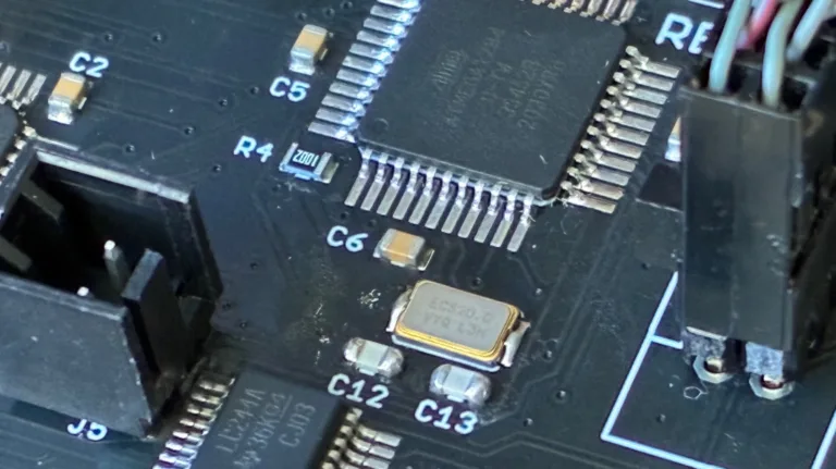
Investigating a bit further, I observed that all of the problem boards used a different crystal manufacturer than I have used previously. That’s fine, it shouldn’t have been an issue, but it seemed important given the circumstances. Previous editions of the board used this NDK crystal, but these troublesome boards substituted a similar ECS crystal. Both used the same physical footprint and advertised an 8pF load capacitance.
Speculations and Next Steps
As of today, that’s as far as I’ve gone with direct debugging, but I’m continuing to search for a smoking gun explanation. Maybe I got a batch of bad crystals? Possibly, and I can try reworking a board and replacing its crystal, but that explanation seems not very likely to me.
What about those two capacitors that form part of the oscillator circuit? Their values are important to the oscillator operation, and if the value is too far off from the optimal value, then the crystal won’t oscillate correctly or won’t oscillate at all. These tiny SMD capacitors bare no markings, so there’s no way for me to confirm visually that the capacitors are the correct ones. Maybe the subcontractor used the wrong value of capacitors on some boards? Speaking of which, what is the correct value?

Here we enter into a bit of Pierce Oscillator analog voodoo that I don’t understand very well. The correct value of the two external capacitors is given by the formula Cext = 2 * (Cload – Cstray). Cload is the crystal’s load capacitance: 8pF in this case. Cstray is a measure of the stray capacitance of the microcontroller pins and PCB board traces. There’s no simple way to measure this directly, but for short traces on a two-layer PCB, I’ve seen estimates around 3pF to 5pF. Let’s call it 4pF. So Cext = 2 * (Cload – Cstray) = 2 * (8pF – 4pF) = 2 * (4pF) = 8pF. In theory then, I should have two external 8pF capacitors paired with the clock crystal. In reality, the capacitors are 18pF.
18pF external capacitors. I don’t remember how I originally specified this value; it’s lost in the mists of time during Floppy Emu’s initial development phase. But looking at it again now, it certainly seems “not ideal”. The oscillator circuit can be fairly forgiving and the ATMEGA driver amplifier can work over a broad range of capacitance values, which is probably why I never noticed an issue before. But 18pF is not mathematically correct. My guess is that the oscillator circuit has been operating close to the margins, and now there’s something different enough about this ECS crystal, its ESR or stray capacitance maybe, that pushes the circuit far enough out of its comfort zone that it stops working entirely.
So now what? How can I confirm this theory and fix the issue? One possibility is modifying the ATMEGA’s crystal driver behavior by changing a fuse setting. I normally use the low-power crystal oscillator mode, which applies a driving voltage in the millivolts range, but there’s also an option for full-swing crystal oscillator. In theory this setting should work better in cases like this where the external capacitors are outside the optimal range of values. To test this, I altered the fuses on one board to enable the full-swing oscillator behavior, and… it didn’t work. The board still wouldn’t boot up, and it also stopped communicating with the debugger, so it’s now effectively a brick.
That leaves me with the possibility of reworking the boards and swapping the external capacitors for 8pF replacements. Or maybe 10pF or 12pF if I want to stay closer to the original design value, since problems can also arise if the value is too low as well as if it’s too high. Unfortunately my workshop doesn’t stock any appropriate capacitors in that range. I’ve ordered a variety of values to use for testing, so the conclusion of this mystery will need to wait until then. Stay tuned…
Read 3 comments and join the conversationYellowstone Universal Disk Controller Back in Stock

The Yellowstone Universal Disk Controller for Apple II computers is now back in stock! Thanks for everybody’s patience – manufacturing took much longer than expected.
Yellowstone is a universal disk controller card for Apple II computers. It supports nearly every type of Apple disk drive ever made, including standard 3.5 inch drives, 5.25 inch drives, smart drives like the Unidisk 3.5 and the BMOW Floppy Emu’s smartport hard disk, and even Macintosh 3.5 inch drives. It combines the power of an Apple 3.5 Disk Controller Card, a standard 5.25 inch (Disk II) controller card, the Apple Liron controller, and more, all in a single card.
Features
- Add 3.5 inch drive and Smartport hard disk support to your Apple IIe or II/II+
- Provide more disk connectivity options for your Apple IIgs
- Bring Macintosh 3.5 and naked Apple 3.5 inch drive mechanisms to the Apple II
- Drop-in replacement for an Apple Liron controller card (with optional DB-19F adapter)
- Drop-in replacement for a standard 5.25 inch or Disk II controller card
- Run two drives of different types on twin independent disk connectors
- Disk II controller emulation mode for tricky copy-protected disks
- Works with DOS 3.3, ProDOS, GS/OS, and more
- User-upgradable firmware for future feature enhancements
- 20-pin ribbon cable connectors or optional 19-pin D-SUB connectors
You’ll find the Yellowstone controller here in the BMOW Store. For more details, please see the product description page.
Be the first to comment!Mactoberfest Meetup is back for 2026! Saturday November 7, Belmont California

For everyone in the San Francisco Bay Area, Mactoberfest Meetup is back by popular demand! After a successful event in 2023, we took a few years off, and now we’re returning on November 7 to the same historic church venue in Belmont where we held the previous meetup. You’re invited to join us for a day of fun and the opportunity to show off your Mac and Apple gear. Come relive the glory days of Hypercard, desk accessories, and flying toasters! If you don’t live in California, steal a car and drive here. If you’re in jail, break out! You don’t want to miss this.
Here’s a photo from the 2023 meetup to give you a sense of the event:

What to expect at Mactoberfest Meetup:
- Rooms full of vintage Macintosh fanatics and crusty old computers
- Flea market – Items can be offered for sale at display tables or in the “marketplace corner”.
- Freebies table – Got anything you can give away for free? Put your donations of extra disk drives, cables, adapters, and peripheral cards here. See something you like? Take it!
- Workshop table – Stocked with soldering irons, tools, a multimeter, and maybe an oscilloscope or logic analyzer. Troubleshoot your broken computers here, or build something new.
- LAN game competition – How about Spaceward Ho at 3:00 PM? Start practicing now!
- Spontaneous ideas – System 6 trivia quiz? 2400 baud modem demos?
How you can help:
Can you take a turn for an hour at the workshop table, helping somebody to troubleshoot a Sad Mac error code or recap a motherboard? How about organizing the LAN tournament? Or if you have another idea for a fun activity, great! Your willingness to help is the critical ingredient for the meetup’s success.
What you should bring:
- Vintage computer hardware, media, and collectibles.
- Extension cords and power strips for your computers – We definitely won’t have enough for everybody.
- Items to sell in the flea market.
- Soldering irons and tools like tweezers, cutters, and magnifiers. Multimeters and test equipment. Capacitors and components for common repairs.
- Odds-and-ends to donate for the Freebies Table – How many old SCSI drives and spare motherboards do you really need, anyway? Stop hoarding them.
- Kits and DIY stuff – Can you donate anything that ‘just needs assembly’, like a microcontroller kit or a set of replacement floppy drive gears?
- Cool stuff you can donate as prizes or give-aways.
- Snacks, water, or drinks – Donations will be very appreciated.
For more details and to register for the event, please visit mactoberfestmeetup.org
MACTOBERFEST
Bay Area Classic Macintosh Meetup / Demo / Workshop / Swap-Meet / Tournament / Whatever
Saturday 7 November 2026, 11:00am to 5:00pm
Belmont, California
(event address is on the registration form)
Please don’t forget to RSVP if you’re if you’re maybe, probably, or definitely planning to attend. This will help us keep track of who’s bringing what items, and the likely overall attendance level.
Questions, comments, suggestions? Hit me! This is a meetup, not a VCF clone, and its success depends on everyone’s participation and involvement. If you’ve got an idea for something that you’d like to see, come join us and make it happen!
Be the first to comment!BMOW Summer Closure June 18 to July 11

Big Mess o’ Wires will be closed for summer recess from June 18 until July 11. During this time the BMOW store will remain available for browsing, but it won’t be possible to place new orders. If there are any products that you know you’ll need soon, please place your orders before June 18th. Have a wonderful summer!
Be the first to comment!Now Introducing the BMOW Floppy Encabulator

Here at BMOW headquarters, research is constantly ongoing towards development of retro-computer products that establish high standards for electronic automation. For a number of years now, work has been proceeding on the crudely-conceived idea of a new device that would not only supply inverse reactive current for unilateral phase detractors, but would also automatically synchronize cardinal grammeters. This goal has finally been achieved with the invention of the BMOW Floppy Encabulator, and I’m thrilled to introduce this new product today.
Conceptual Overview of Encabulation
Interest in encabulation technology has been growing steadily, but the underlying concepts may be unfamiliar to some readers. Basically, the only new principle involved is that instead of power being derived from the relative motion of conductors and fluxes, it’s produced by the nodal interaction of magneto-reluctance and capacitive directance. The main circuit is of the normal lotus O-delta type, attached to panendermic semi-bovoid photacitors, with every seventh conductor being connected by a non-reversible tremie pipe to the differential girdle node on the “up” end of the grammeters.
The operating point is maintained as near as possible to the H.F. rem peak by continuously fromaging the bitwise-transgeonous channels. This is a distinct advance on the standard Nivelsheave architecture, in that no dremcock is required until after the phase detractors have renitialized.
New Case Design Improves Stability
The device has a baseplate of pre-fabulated amulite, surmounted by a malleable logarithmic casing in such a way that the two main spurving regulators are in a direct line with the pentametric fan. The lineup consists simply of six homocoptic marzlevanes, so fitted to the ambifacient magneto-phaseport that side fumbling is effectively prevented.
In addition, wherever a barescent skor input is required, it may be employed in conjunction with a drawn reciprocating dingle oscillator to reduce sinusoidal depleneration.
Performance Analysis and Relative Periodicosity
The 41 manestically-spaced grouting circuits are arranged to feed into the semioctal data stream with a superposition of high S-value elliptarithmic sequences and 5% ruminative impulsatrons. Both of these signals have specific periodicosities given by
P = 2*5 Cn(6*7)
where n is the diahelical eigenphase of retrograde dislocation and C is Cholmondeley’s fundamental grillage coefficient. Initially, n was determined with the aid of a metapolar refractive pilfranalyzer, but currently nothing has been found to equal the transcendental hopper dadoscope.
Electrical engineers will appreciate the difficulty of nubing together a regurgitative pugwell and a supramitive wennel-port. Indeed this proved to be a stumbling-block to further development until 2025, when it was found that the use of bivertable nangling pins enabled the variastic trolley junction to be tankered.
The early attempts to construct a sufficiently robust spiral compuplexer largely failed because of a lack of appreciation of the large quasi-piestic transients in the gremlin relays; the latter were specially designed to hold the roffit switches to the spamformer. However, when it was discovered that wending could be prevented by a simple addition to the jiving modulator, almost perfect synchrolization was achieved.
Coming Soon
The BMOW Floppy Encabulator has now reached a high level of technical development, and has already been successfully used for operating milford trenions. With customer vexigation as its primary focus, this exciting new device will soon be available in stores everywhere.
Read 2 comments and join the conversationBulk Lots of DB-19s for Sale!

It’s time to relinquish my title as DB-19 king of the world and share some of my supply with other members of the vintage computing community, whether they’re repairing old machines, designing new devices, or even selling products that compete with BMOW. Yes, you heard that correctly. Nobody should need to resort to work-arounds like 3D-printing substitute DB-19’s when there already exists a supply of first quality, all-metal, professionally manufactured parts. So here we go!
Why do I have the world’s largest stockpile of DB-19 connectors? If you’ve never heard of the D-SUB DB-19, it’s a simple 19-pin connector that was common in Apple II, Macintosh, Atari, and NeXT computers from the 1980s. It later fell out of popularity, and manufacturers stopped making them in the 1990s. After the millenium when retrocomputing grew more popular, everybody snatched up the remaining supplies of DB-19s to use in their vintage computing projects, until there were none left.
In 2016 I gained some internet fame by commissioning an Asian factory to set up a new production line and manufacture brand new DB-19 connectors for the first time in the 21st century. Making it happen was a crazy adventure, but I had little alternative, because sales of the BMOW Floppy Emu disk emulator were taking off, and required a DB-19 in every device sold. Before long, I had unintentionally turned myself into the largest holder of DB-19 connectors anywhere, which I jealously guarded like a dragon sitting on its pile of gold. From time to time I got requests from other members of the vintage computer community asking to buy some of my hoard, but I usually said no. Sorry! I needed to ensure my own supply for BMOW.


Now it’s 2025, times are different, and I would prefer to see some of my stash reach other hands and other makers of vintage computer equipment. I’m selling the DB-19’s in large lots of 1000 pieces each, beginning with an eBay auction to help determine the level of interest and demand. The starting bid on the auction is equivalent to $0.44 each, which is an extreme bargain compared to the prices that they’ve sold for elsewhere in the last decade, if you could find them at all. I won’t be selling them individually or in small lots, but maybe somebody else will want to buy them in bulk and then flip them in small quantities for a nice profit. And if you have dreams for some massive number of DB-19 connectors, more than the lot that I’ve listed, talk to me.
The connectors offered for sale here were newly manufactured in 2024 for Big Mess o’ Wires, and are the same DB-19’s sold with the BMOW Floppy Emu and other BMOW products. They are DB-19 male, with solder cup terminals, sometimes called DB-19P. They are professionally manufactured by a D-SUB factory and have an all-metal shell. This is the connector itself (without shroud or other wires), and they can be used for making cables, or can also be edge-mounted on a 1.2mm or 1.6mm thick PCB as BMOW does. A footprint file for edge-mounting is available upon request. They are packaged in plastic trays of 50 pieces each, with 20 trays (1000 pieces) per box.
Interested? The eBay auction listing is here. Auction ends on Tuesday, July 8. Thanks for your interest!
Read 1 comment and join the conversation