

Star Ring: Abusing the PCB Fab
Why use a PCB silkscreen when you could showcase the shiny gold metal layer? Why build a rectangular board when you could have strange and wonderful shapes? And why settle for a dull LED flasher when you could have something crazy? I went a little bit overboard with this one, and I’m unsure how to even describe it. It’s a wearable LED blinky, with some terrible (or amazing?) abuse of the PCB fabrication process, many eye-catching light displays, and careful attention to power usage to ensure long battery life. For lack of any better name, I’ll call it the Star Ring.
PCB
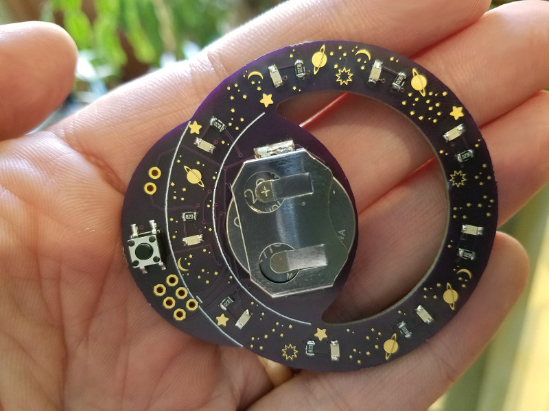
The PCB was made at OSH Park. Yes, the fab really will cut PCBs in this shape, and with a large hole in the middle too. Whatever is drawn as the outline layer in the design software, that’s what they’ll cut, so I won’t limit myself to boring rectangles. In this case the board is a 2-inch diameter ring, where a 1.5-inch diameter disc has seemingly been cut out of the center and repositioned behind the ring and overlapping it. In Eagle, it’s actually a many-sided polygon rather than a true circle, but the difference isn’t visible.
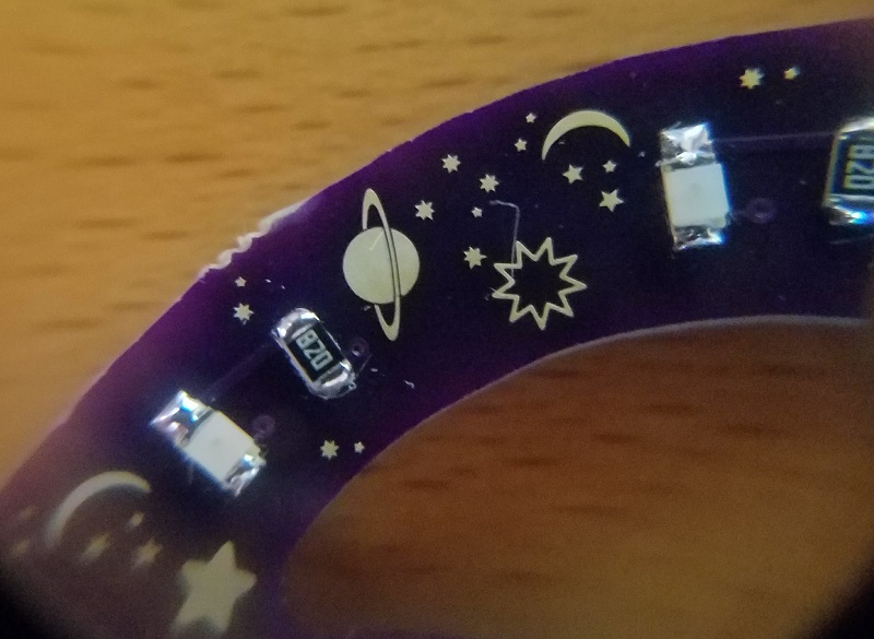
Second, the artwork. Rather than using the silkscreen to draw stars, moons, and planets, I put them into the top metal layer. Because this PCB was made with ENIG plating, the artwork appears as shiny gold. It’s a unique look, and it’s also extremely crisp and high resolution, much higher than I would get with the silkscreen layer. Some of those stars are only 0.4 millimeters across, but they still show up clearly when viewed under a 10x magnifying lens:
Electronics
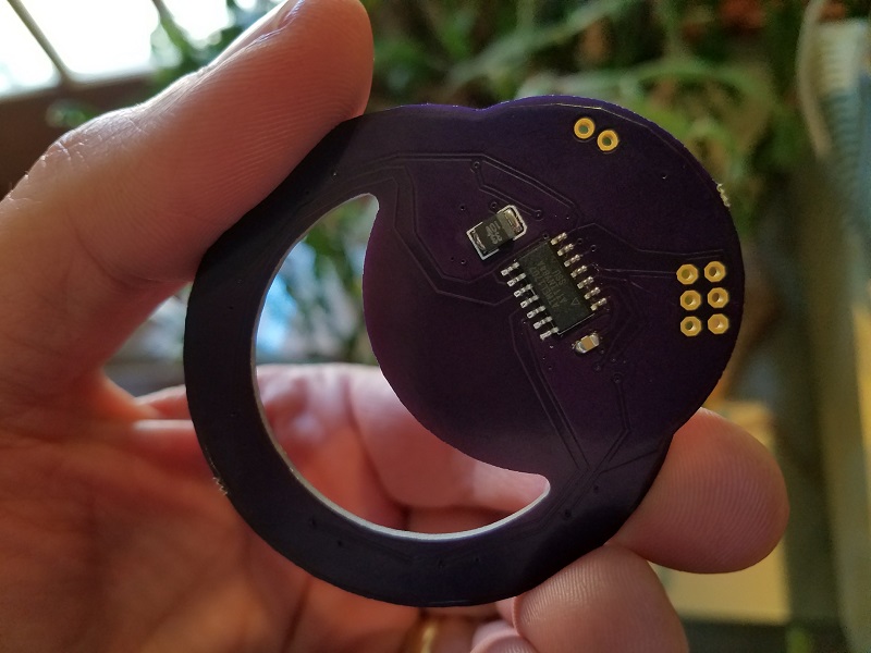
The board’s primary electronics are about as simple as you can get: just a microcontroller, a pushbutton, and some LEDs. Even including the CR2032 battery, current-limiting resistors, and a couple of capacitors, it’s a bare minimum of components. The microcontroller is an ATTINY84A, and is hidden on the back:
The ATTINY microcontrollers are like the little brothers of the better-known ATMEGA parts found in the Arduino and Floppy Emu. This was my first time using an ATTINY chip, and I was excited to give it a try. Aside from having less RAM and less flash memory than ATMEGA parts, I was hard-pressed to spot any difference. Those who scour the datasheet will discover that the ATTINY chips have fewer built-in hardware peripherals, or the peripherals have fewer features than their ATMEGA counterparts, but for most people the differences aren’t important. The great thing about ATTINY chips is that they come in small packages and are very inexpensive. This particular chip is only 80 cents in single-unit quantities.
Lighting LEDs with PWM
Each of the nine LEDs is connected to an ATTINY output pin, and to an 82 ohm current-limiting resistor. They’re amber LEDs with a forward voltage of 2.0 volts, according to the datasheet. With a 3.0 volt battery, the math says that will create a 1.0 volt potential difference across an 82 ohm resistor, resulting in a current of 12.2 mA. Unfortunately the math is completely wrong.
The CR2032 battery has significant internal resistance of about 15 ohms, which further limits the current. And the ATTINY output pin voltage will droop lower than the supply voltage when it’s delivering many milliamps of current, so the voltage applied to the LED will be something less than 3.0 V. The more LEDs that are lit simultaneously, the more noticeable this effect will become. I attempted to do some complex math and experiments with a dozen different resistor values, in order to find the optimum value, before I concluded that it didn’t really matter. Anything in the 60 to 120 ohm range is probably fine. With the 82 ohm resistors, my tests showed an LED current of 7.9 mA with a single LED lit, and 6.0 mA each with two LEDs lit.
Lighting up all nine LEDs is more challenging. It’s not possible to directly power all nine at the same time, because that would draw more current than the battery and ATTINY can provide. The LEDs would get noticeably dim, and the supply voltage would get pulled down, possibly to a voltage low enough to cause a microcontroller malfunction or reset. Star Ring creates the appearance that all nine LEDs are lit by turning them on and off very quickly, with no more than three LEDs ever turned on at the same instant.
With the necessity of modulating the LED duty cycle for power reasons, it was only a short step further to a full PWM control for each LED. This made it possible to change the brightness of the LEDs dynamically, creating a pleasing “analog” look that contrasts with the typical full-on/full-off illumination of typical LED displays. Lighting an LED with 2% duty cycle looks dim, lighting it with 80% duty cycle looks bright.
The ATTINY has two hardware peripherals that can handle this type of PWM, but because Star Ring has nine LEDs, I had to design a software PWM solution instead. With some passably optimized code, and the ATTINY running at 4 MHz, the 9-channel PWM LEDs blink at 1148 Hz. This is fast enough to be mostly invisible to the human eye. The software PWM supports 16 brightness levels, and each brightness level maps to a duty cycle between 0:64 (off) and 64:64 (100% on).
While developing the PWM code, I discovered something interesting about the human eye and brain. I assumed that an LED with 80% duty cycle looks twice as bright as one with 40% duty cycle, but I was wrong. In fact, I’m hard-pressed to notice any visible difference in brightness, and at most I will say the 80% looks slightly brighter. Because we humans have evolved to cope with vast brightness differences in our environment, from the dazzling noon sun to the faintest starlight, there’s a decidedly non-linear mapping between the energy output of a light source and its perceived intensity. There are various formulas that attempt to convert between the two, but I just created a conversion table and then tweaked the numbers until it looked good. The result is that an LED set to 50% brightness doesn’t get a 50% duty cycle of 32:64, but only 15:64.
Side note: I couldn’t use green or blue LEDs here, because their forward voltage is about 3.0 volts, the same as my battery voltage. In this circuit, green/blue LEDs would be very dim at best. With a 3.0 volt battery I’m effectively limited to using yellow or red LEDs.
Blinky Functions
Even with the help of PWM, it’s not possible to animate the LEDs all the time without exhausting the battery in a matter of hours. Instead, Star Ring implements 12 different LED animation patterns that play periodically, with each pattern being about two seconds long. The patterns span the range of my LED-blinking creativity: a spinning wheel that gradually slows (shown in the title image), a flickering candle, fireworks, stars that slowly fade in and out, and many others. Pressing the button wakes up the device and plays the next animation pattern. Once awake, the device will also spontaneously play a new pattern about once per minute. Once in a rare while, it will play a special longer pattern. If you’re a 9-year-old kid, this is like the equivalent of “rare” Pokemon cards, and will keep you engaged with the Star Ring for long periods just to get that payoff.
Wearable?
My vision for Star Ring is to make it a wearable device, either as a shirt/hat pin, a necklace, or something else. I haven’t yet figured out the best attachment method for clothing, so for the moment I’m hanging it off a shirt pocket zipper. If anybody has a great idea on how I could incorporate a pin or a snap into the PCB design, please let me know.
The periodic but infrequent animation patterns are intended to support the wearable design. Even if the battery allowed it, a constantly-animating LED display would quickly grow annoying and get switched off, or else would be tuned out and ignored. But when Star Ring periodically flares to life, it always grabs attention. “What that?” people will ask. Then as I stand talking to them, they’ll interrupt “oh it did it again!” It naturally draws people in, and is a great little accessory for the kinds of events that welcome a blinking PCB with stars and moons (whatever those might be).
Power Consumption and Battery Life
The CR2032 battery provides a paltry 220 mAh at 3.0 volts. That’s not much. The 220 mAh capacity also assumes a current draw of only 0.1 mA. If the circuit draws current at a higher rate, the effective battery capacity will be even less. But with a bit of experimentation, I was able to design the hardware and firmware to get a projected battery life of 1 year. Not bad!
While an LED animation pattern is playing, the current from the battery varies between 10 to 24 mA depending on the pattern. Clearly the Star Ring can’t afford to do that very often. With no LEDs illuminated but the ATTINY still running, the current is 2.9 mA, which is still far too high. To save power, in the time between each LED animation pattern the ATTINY slows its clock to 31 kHz, disables all hardware peripherals except the timer, and enters idle mode. In this mode the main CPU clock is halted, but the peripheral clock continues to run, so the device can be awakened from a timer interrupt or external pin change interrupt. The current from the battery in this state is only 99 microamps. Much better! According to the datasheet it should be even lower, about 10 microamps, but I’ll take what I can get.
But even 99 microamps is too much current for the long term. That rate of current would deplete the battery in three months all by itself, without ever illuminating the LEDs. To save more power, if an hour has passed without the button being pressed, the ATTINY will enter power-down mode. In this mode all clocks are halted, and the IO buffers are disabled except for the one pin connected to the button. The device can’t be awakened by a timer interrupt, but now requires an external pin change interrupt from the button. When in this state, the current from the battery is a minuscule 120 nanoamps. Yet this tiny amount of current is still enough to maintain the CPU state and the contents of RAM. As soon as the button is pushed, Star Ring immediately jumps back to life and continues with the next LED animation pattern.
Sometimes the operator may want to force Star Ring into power-down mode immediately, without waiting for the one-hour timeout. Pressing and holding the button for a few seconds will play a “shutdown” LED animation, followed by the device going immediately to power-down mode. The battery life in this state is effectively infinite, or as long as the shelf life of the battery. No further LED animations will play until the device is reawakened by another button press.
Next Steps
I don’t think this is a product for sale – unless 20 people immediately respond saying they want to buy a Star Ring. It would be challenging to mass produce, because the intentional misuse of the top copper layer for decorative purposes means it would be difficult to use a solder stencil and an oven to assemble the boards. Solder paste would stick to the exposed copper of the moons and stars, spoiling the design. So this is probably just a project of personal whimsy for myself, friends, and family.
Commercial or personal, I do have a couple of ideas for Star Ring version 2:
- Put the battery on the back, and the ATTINY chip on the front. This would look better, since the battery is kind of ugly.
- Add mounting holes, clips, snaps, or something else to provide for easy use as a wearable.
- Use a right-angle pushbutton instead of a standard button. With a clothing mount, the standard button may be painful or socially awkward to push in, against the body. A right-angle button would push parallel to the body.
- Use red/yellow dual-color LEDs, that are really two LEDs in a single package. It might require an ATTINY with more pins, or perhaps a couple of extra transistors, but it would enable many more creative possibilities for the LED animation patterns.
Happy blinking!
Read 17 comments and join the conversation17 Comments so far
Leave a reply. For customer support issues, please use the Customer Support link instead of writing comments.
Nice project and very nice artwork. Sometimes simple, frivolous things are just right.
I don’t understand why you couldn’t make a stencil. Simply don’t put the stars into the stencil layer. You do have a separate stencil layer, don’t you?
Finally, I’ll just leave a pointer to my similar project from a couple of years ago. I also experimented with copper layer artwork, though mine was less adventurous than yours.
https://github.com/kbob/Blink-Eras
https://oshpark.com/shared_projects/PJpQLumx
Oops, KiCad calls it a “paste layer” not stencil layer.
Nice work Steve, will this be shared for OSHPark ordering or remixing?
A wearable pin attachment option would be nice. Also I would suggest putting the battery on the bottom and MCU on the top with all other SMD components. Also to make it smaller and less obvious the ICSP does not have to be that large or in 2×3 configuration, or even through hole, could be just a series of pads in a little circular pattern. Then you can make a jig from 2 stacked PCBs and drill the TPoints to insert/solder pogo pins and hold them together like a sandwich. the pogo pins then match your TP pads of the production PCBs.
And one last thing – for small kids lithium is ultra dangerous if they swallow a coin cell, either some mechanism to lock it or perhaps even using hot glue would work…. just something to keep in mind for the users.
Kbob, I really like your project! It’s a great electronic parody, and it’s true – today’s designers will use a fancy 32-bit microcontroller where past designers might have used a 555 timer or just a few transistors. Whenever I look at a classic circuit like Forrest Mims’ siren or something, I’m a little embarrassed at how simple it is, and at the fact that I struggle to understand how it works.
Too bad your pogo jig didn’t work – it looks quite nice. I’ve had success with the other style of pogo setup you describe, with the board sitting on top of the pins, and held by a clamp. https://www.bigmessowires.com/2017/07/16/pogo-pin-test-board-for-adb-usb-wombat/
Maybe a solder stencil would be OK with the copper artwork, if the stencil were applied carefully. I always manage to smear solder paste around a bit, even with a stencil, and I’d surely smear some paste from the LED and resistor pads onto the nearby copper artwork. The prototype shown here was assembled with an iron.
Felix, yes I think I’ll put the design on Github for others to experiment with. I agree about swapping the battery and mcu locations. Good idea about using a smaller ICSP footprint too. The full footprint was convenient for development, but not really necessary if all that’s needed is one-time programming.
I once had to design a tiny board and used the 2×3 ICSP. But the board itself was smaller than the ICSP through hole, so I made the ISCP like a tab so i could easily snap it off after programming. 🙂 Just an idea.
BTW the pogo jig you had there only holds the pins from the bottom. Here’s one that is more complex with more pins.
Oops your site strips html tags.
Having the pins held by 2 PCBs makes them very resilient and rock solid WRT alignment. Adding some extra hardware helps align larger boards without the need of clunky holders or other complex mechanisms.
https://imgur.com/eO7RI5j
https://i.imgur.com/eO7RI5j.png
How do you specify a snap-off tab in the PCB design? Do you add lots of tiny unplated drill holes to score the break-off edge, or is there some simpler way?
The board was for a medical application where a special sensor had to be inserted in the patient’s ear. Notice the MCU on the bottom PCB. The ICSP was for 1 time programming, it was then cut off after testing and before final assembly. This is it sitting on a penny:
https://imgur.com/1ikYVX6
This is beautiful! It reminds me of Pimoroni’s bearables https://learn.pimoroni.com/tutorial/sandyj/getting-started-with-bearables
But somehow they managed to use green blue and even white LEDs.
I like that you used an ATTiny instead of a PIC. I find Atmel devices way friendlier, specially when using the Arduino IDE.
Thanks! The Bearables look very similar to this. I’ll have to investigate the “sewable hook” they use for attachment, though I’m not clear what that means. I’d hoped for a less permanent method of attachment than sewing, but haven’t found a simple one yet. A few small holes in the PCB would make it straightforward to sew the Star Ring onto a hat or bag, so maybe I should do that.
There’s a Star Ring version 2 PCB coming in a few weeks. It swaps the locations of the ATTINY and the battery, and changes the button to a right angle button. I also made some changes to the silkscreen so the disc behind the ring looks like a full moon. I’m interested to see how that turns out. I almost switched to dual-color LEDs too, after I determined I could control them with the same hardware I’m using now. But that would involve designing all new LED animation patterns, and I think I’ve sunk enough time into this project already. I’ll post a video of the other patterns once v2 is ready.
It looks like I was wrong about green and blue LEDs having too high of a forward voltage for use with a 3.0V battery. Searching Digikey, I see some green LEDs with 2.0V forward voltage, and some blue with 2.2V.
For fancy PCB designs take a look at https://www.boldport.com/
For example: https://www.boldport.com/products/the-monarch/
Hi Steve, thanks for the ideas about gradually reducing the power modes and shifting from watchdog to hardware interrupt.
If you do revise this board and put the ATtiny on the front, I think it would look great if you gave the IC some ENIG “solar panels and antennae” to make it look like a satellite!
You use a stencil for this easily if you have access to a 3D printer. I’ve done a couple projects with odd-shaped boards. What I did was export the outline/dimension layer from EAGLE as a DXF file, and then import that into Fusion360. You can make a pseudo-like mold that the pcb can sit in and have a flush surface to lay the stencil on top of.
I think 3v white LEDs might work. I made a little device with an msp430, 2 AAAs and a white led (no power limiting resistor). First version was rough and ready with power usage optimisation to follow. It lasted so long I never bothered updating it. I’m pretty sure the led was 3v, I was surprised it even worked once.
Hello. I read that this is not a commercial project, but I don’t see a github link. If you have the original files, maybe you can share them?