

Make Your Own Katy
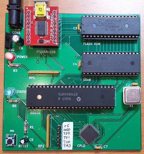
If you’re crazy enough to want to build your own 68 Katy, I’d like to help you do it. The PCB version is the easiest way to get started. Compared with the breadboard version, it replaces all of the glue logic, timers, and other miscellaneous components with a single CPLD. The number of status LEDs is also reduced from eight to one, and there’s a small change to the serial status address mapping. Otherwise it’s functionally identical to the original breadboard prototype. Get a PCB, solder the components, burn the ROM, and you’ll be in business.
Assembling the PCB requires soldering one surface mount component, the 44 pin CPLD in TQFP package. It can be soldered with a standard iron using the drag soldering method (my preference), with hot air, or with a toaster oven reflow. The rest of the components are easy through-hole parts.
You’ll need an EPROM burner to program the initial flash ROM data, as well as a JTAG programmer for the CPLD. I used a Bus Pirate with the XSVF player firmware to program the CPLD.
Note that the PCB and breadboard versions of 68 Katy are not binary compatible, due to a small difference in their memory maps. If you’re building the PCB version, be sure to use the files linked here, and not the breadboard version files.
PCB Version: Parts List
- Motorola 68008 CPU, 8 MHz, 48-pin DIP package
- AM29F040B or SST39SF040 4 megabit Flash ROM
- BS62LV4006PIP55 4 megabit SRAM, or compatible substitute
- Xilinx XC9536 CPLD – not XC9536XL
- Sparkfun FT245RL USB to FIFO breakout board
- 12 MHz metal can oscillator
- bypass capacitors, resistors, LEDs, buttons, switches, sockets, etc. – complete parts list
PCB Version: Files
- schematic and board layout – Board definition in KiCad format
- Gerber files – For getting a copy of the PCB made at a fab like Seeed Studio
- CPLD source – Xilinx ISE project and Verilog source code for the CPLD
- 68katy.xsvf – JTAG configuration file for the CPLD
- monitor.asm – My ROM-based monitor/bootloader program. I used Easy 68K to assemble it.
- monitor-plus-linux-pcb.bin – This is the final binary image I programmed into the flash ROM, containing the monitor/bootloader program with the uClinux kernel concatenated to it beginning at address $003000
- virtualboxes.org Ubuntu machine – For Linux cross-development, I used Ubuntu 12.04 32-bit running as a virtual machine under Virtual Box. Don’t use the 64-bit version, or the 68K toolchain won’t work. You can use this pre-configured Ubuntu Virtual Box machine image. Username “ubuntu”, password “reverse”
- uClinux-dist-20040218 – I started from the February 18, 2004 release of uClinux. This is the unmodified version.
uClinux-20040218-pcb.tar.gz – This is my modified version of uClinux. It includes code for kernels 2.0, 2.4, and 2.6, but I only ported kernel 2.0 for 68 Katy. Search the code for “68KATY” to find my changes. - m68k-elf-tools-20030314 – You’ll need a 68K cross compiler and other tools in order to build the uClinux source code. I used m68k toolchain 20030314. It’s supposed to be a self-extracting shell script, but that didn’t work for me. I had to extract it manually, like this:
user@ubuntu$ tail -n +43 m68k-elf-tools-20030314.sh | gunzip > tools.tar

user@ubuntu$ tar xvf tools.tar
Startup
Assemble the PCB. Attach a regulated 5V power supply, and turn on the power switch. Use the Bus Pirate or another JTAG programmer to program 68katy.xsvf to the CPLD – the board must be powered when you do this, but components other than the CPLD don’t necessarily need to be present yet.
Use an EPROM burner to program monitor-plus-linux-pcb.bin to the flash ROM, then place the ROM chip in the board’s socket. Place the CPU and RAM in their sockets as well.
Attach a USB cable to the FT245RL module, and plug it into your computer. The FT245RL module doesn’t need to be connected to the 68 Katy board yet – it’s powered by the USB cable. If necessary, install the FTDI virtual serial port driver software for your computer. When complete, your should see a new virtual serial port like COM4. Now place the FT245RL module in its socket on the 68 Katy board.
Turn on the 68 Katy board. Use terminal software like Tera Term to open the serial port where the FT245RL is connected. The serial port speed and parity settings actually don’t matter, although choosing a faster speed will result in faster file transfer times when sending updates to the board.
Press the RESET button on the 68 Katy board. If everything is working, you should see the monitor prompt zBug(ROM) for 68Katy (press ? for help). Press ? to see a list of available commands. The monitor can load Motorola S-record files, view or disassemble memory, and many other useful things. The uClinux image is stored in the flash ROM beginning at address 003000 hex. To start Linux, from the monitor prompt type j 003000.
Using the provided source code, you can modify the monitor program, the uClinux filesystem contents, or the uClinux kernel. Use a hex editor or other tool to concatenate the uClinux image file 68katy.rom to the monitor program monitor.bin. The combined result must be no larger than 480K. Note that 68katy.rom itself is a concatenation of the uClinux kernel code kernel.text, kernel initialized data kernel.data, and the read-only Linux filesystem image romfs.img. To update the flash ROM with the new monitor or uClinux, from the monitor prompt type u, then use the terminal software’s file transfer option to download the concatenated file. If using Tera Term, make sure to select the option to send the file in binary format, not text.
Have fun!
Read 23 comments and join the conversation23 Comments so far
Leave a reply. For customer support issues, please use the Customer Support link instead of writing comments.
Would this design work with later m68k cpus?
Yes, it should definitely work with a 68000, if you expand the data bus to 16 bits wide. I can’t think of any reason it wouldn’t work with a 68020 or 030 too. Those chips aren’t available in DIP packages though, so they’re harder to prototype with.
Hi
I have a completely irrelevant question but I didn’t know how to get in touch. I understand that you could programm a CPLD via a micro-controller. My question is that, did you have to put pull-up resistors On the JTAG tracks?
Regards,
Pej
The CPLD has internal pull-up resistors for the JTAG signals, so external pull-up resistors aren’t necessary. Details are in the Xilinx datasheet.
Hi,
does the Design support a bigger Memory Chip ?
512Kb Ram is very limited for anything useful.
The 68008 only has enough address pins for 1 MB of addressable memory, of which the Katy design uses 512K for ROM and 512K for RAM. You could build a similar machine with a 68000, which has more address pins. It can handle up to 8 MB of addressable memory if I recall correctly.
Hello,
Why the CPLD needs to be the old and expensive XC9536? The newer XC9536XL are 5V tolerant and should be able to drive 5V TTL inputs just fine, especially when you have only so short bus.
follow-up – of course, assuming that you add a 3.3V regulator for the CPLD (the lack of the regulator is the only reason I could imagine why one would need to use the old non-XL version).
I originally intended to use a XC9536XL, but I forgot to include a 3.3V supply for it when I designed the PCB. Substituting the older XC9536 allowed me to use the existing PCB without requiring any other changes.
Right, makes sense. Perhaps put a note to your part list about this – the old non-XL parts are obsolete and starting to get harder to find.
Pity that the board doesn’t have any expansion connector, though. I have started to design a similar machine using the ISA card format, using a cheap ISA backplane I got from eBay.
Here is some ideas I have regarding the Katy I am wondering about:
* Can the Katy be built using the 68SEC000? That chip can operate with a 3.3V supply voltage, expanding the range of useable programmable logic and memory options significantly, for example: all those 3.3V FPGAs like EP4CE6E22, 3.3V SDR SDRAM (with the FPGA acting as DRAM controller – in fact if the FPGA allows you can even use 2.5V DDR SDRAM, and throw in a paging mechanism you can even get 64MB of RAM on a single cheap DRAM chip,) a lot of video output options (for example SSD1963 which is a LCD output controller with built-in VRAM,) even raw NAND chips.
* If staying on the 5V route, how feasible is it to use 68010 + 68451 as the processor complex? The 68451 MMU can allow regular Linux (not the MMU-less uCLinux) to run, greatly expanding the available software library.
You could certainly use the 68SEC000 – it’s one of the options I considered. It’s only available in surface mount packages, though, so you couldn’t build it on a breadboard.
A discrete MMU or a chip with built-in MMU like 68030 would be interesting, if you wanted to do something more advanced. I found porting the simple non-MMU Linux to be difficult enough. 🙂
If you want to see what’s possible with a more complex 68008-based homebrew computer, check out https://www.ist-schlau.de
Making a design of my own (And your documentation has been really helpful as a general guideline) using 16bit 68K. I’ve been looking through the FT245RL documentation and I just can’t quite wrap my head around how it works with the 68K/CPLD. I noticed you use the interrupts, but again, don’t understand how that ties in. Originally I was planning on using RS232 driver and having a RS232-> USB cable, but saw you use the 245 chip and got really excited about that. If you could, I’d really appreciate some light in how the 245 talks with CPU/CPLD or any links that explain this. Thank you so much for your time, effort, and clear documentation!
The CPU reads and writes bytes directly to the FT245R, since they share the data bus. The CPLD manages the control signals that make this possible.
FT245R by itself is pretty simple- it’s kind of like a 1-byte SRAM, with an output enable RD and write enable WR. It also has status flags RXF and TXE to indicate when a new received byte is available, and when the transmit buffer is full.
Linux requires an interrupt to signal when a new received byte is available – the OS can’t just sit there continuously polling RXF. That’s where the CPLD comes in to play:
assign _ipl1 = ~(~_rdf && _ipl2); // USB serial input interrupt, don't assert if timer interrupt is activeasserts IPL1 if RXF is asserted and IPL2 is not asserted (gives priority to IPL2, the timer interrupt). The interrupt handler reads the byte from the FT245R and processes it. The actual reading and writing of the data byte is managed as a pair of memory-mapped addresses (actually a range of addresses where the lower bits are don’t care), so it looks the same as a RAM access to the CPU.
// 78000 - 79FFF : serial in// 7A000 - 7BFFF : serial out
wire isdevice = (addr[19:15] == 5'b01111);
assign _rd = ~(ismem && isdevice && rw && (addr[14:13] == 2'b00));
assign wr = (ismem && isdevice && ~rw && ~_ds && (addr[14:13] == 2'b01));
If you’re not using Linux, but instead are running BASIC or some homebrew command interpreter, you could begin with a polling-based approach and not worry about using interrupts.
Wow, Thank you so much! That’s extremely helpful!
I cant seem to find the article or info (if it was published) on how you compile a program to run under the uCLinux environment, for example a hello world app, or better yet, an LED flashing/knight rider source code, and how to compile it.
Would it be the same as the way you compile the Kernel? Same toolchain?
I also eventually need to figure out how to make it work with a standard 16550 UART type setup but I will worry about that later.
Thanks!
I have all the parts to build a 68 Katy except the FT245, which has
been discontinued. I have the Adafruit FT232H breakout, and this
chip is supposed to be able to operate in asynchronous FIFO mode
like an FT245. I can figure out how the pins map between the
breakout boards from the datasheets
and the picture of the 245 board on the Sparkfun website. However,
I’m having trouble figuring out how to use ftdi_eeprom to reprogram
the FT232H to go into FIFO mode. Has someone made a 68 Katy work
with an FT232H or another chip which is currently available?
Discontinued? I see thousands of FT245 in stock at Digikey, Mouser, etc.
I decided to build this 68008 design and ordered 5 boards from jlcpcb.com before I found out that the sparkfun FT245RL breakout board was discontinued. Ebay has what seems to be a similar version to the original FT245RL. Look up Item number 114086272939 on ebay. Would someone who has the original Sparkfun FT245RL breakout board please verify the pinout to item 114086272939 on Ebay? It would be very much appreciated. Thank you all for any help anyone cares to give. I’d rather not have to resign this pcb just because of a discontinued parallel to USB FT245RL breakout board.
Look at the board schematics – each of the signals connected to the FT245RL breakout is labeled. Here’s a photo of the underside of the FT245RL: https://www.bigmessowires.com/wp-content/uploads/2020/02/20200213_122730.jpg
I have 20 bare boards to build the sparkfun ft245 board
I can spare a few of them, if anybody wants to build there own.
FT245RL Breakout board design is here
https://github.com/sparkfun/FT245RL_Breakout