

Hot Plate Reflow Soldering: Round 1
Last week’s attempt at reflow soldering with hot air didn’t go very well. Today I gave it another try with an electric hot plate, and it still didn’t go well, but maybe I learned something in the process. Will the third attempt bring success?
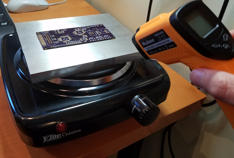
My goal this time wasn’t really to solder anything important, but simply to test how quickly the hot plate heats up, and where on the control dial’s warm-low-medium-high scale will produce the necessary temperatures. I used an infrared thermometer to measure the surface temperature of the burner.
Part 1 – Naked Hot Plate
With nothing on it, and the dial set to “medium”, the hot plate temperature increased by about 100 degrees Celsius per minute, reaching the 183 C melting point of solder after roughly 90 seconds. From there it kept on going to 300+ C before I aborted the test, so “medium” was clearly too hot. I later found a setting just above “warm” that produced a steady temperature about 150 C, which is about right for pre-soak. Unfortunately there was a large amount of temperature variation between different areas of the burner – about 45 deg C. This could cause problems form uneven heating if a PCB were placed directly on the burner.
Part 2 – With Aluminum Heat Spreader
For my second test, I placed a 6 x 6 x 0.5 inch aluminum block on top of the burner, to use as a heat spreader. I put an old PCB on the aluminum block, with solder paste and a few small capacitors. It was quickly obvious that the aluminum block was far too thick for this purpose, with much too high a thermal inertia (what’s the right term for this?). Its temperature barely rose at all initially, but then it continued to climb for several minutes even after the hot plate was turned off, as heat was absorbed from the still-warm hot plate.
When the aluminum and PCB reached about 100 C, I decided to turn the hot plate back on to “medium” and just let it rip. The temperature rose by about 15 deg/minute, which is pretty slow. Once it reached roughly 210 C and the solder paste was nice and melted, I turned off the hot plate, but the temperature kept going up! The hot plate burner was probably still at 300+ C, and the aluminum was still slowly absorbing heat. I had to slide the PCB off the aluminum while the solder was still molten in order to allow it to cool. Not good.
The temperature variation between different areas of the aluminum was only about 5 deg C. But the temperature variation between different areas of the PCB sitting on the aluminum was as much as 90 deg C – yikes! The test PCB was very slightly bowed, resulting in some areas not actually touching the aluminum, making them much colder than other areas just an inch away. I’m not sure how to fix that. Maybe I could press down on the PCB with a non-conductive tool while it’s cooking, but that would make it difficult to use the thermometer or adjust the control dial, and would make it almost impossible to reflow more than one board at a time.
I was surprised to see how long it took the hot plate to cool off after use. More than an hour after finishing these tests, the aluminum block was still at 55 C. That could be a problem if I need to run several batches of PCBs through hot plate reflow. Will I need to wait 10, 20, 30+ minutes between batches, to allow the hot plate to cool?
What Next?
Maybe a reflow toaster would be easier than a reflow hot plate, but most of the advice I’ve heard says the opposite. I’m also very reluctant to use a toaster, since even a small toaster would be hard to fit in my work area, and it’s tough to see inside a toaster to observe what’s happening during reflow. I really like the open loop simplicity of the hot plate method, and would prefer not to mess around with toasters and thermocouples and temperature controllers unless there’s no alternative. If it comes to that, I might just give up on reflow and stick with hand soldering.
For the next test, I’ll use a much thinner aluminum plate, or maybe just a couple of sheets of aluminum foil. I think the 100 deg/minute warming I observed without the aluminum block is actually about the right rate for reaching the pre-soak temperature, if I can find the necessary control setting to pause it there for a minute afterwards. But I probably still need something to help even out the hot spots on the hot plate burner, to ensure the PCB is warmed evenly.
Read 6 comments and join the conversation6 Comments so far
Leave a reply. For customer support issues, please use the Customer Support link instead of writing comments.
Put your PCB into a disposable aluminum foil pan/tray. This way you can easily lift the PCBs off the plate once the solder flows and avoid overheating due to inertia. It may also help a bit with spreading the heat.
Just don’t bump the tray or parts will slide of the pads 🙂
PS: Putting a second tray on top can help too, but will make it harder to observe.
I like that idea! Have you tried it? Most pans like that have raised patterns on the bottom, so some parts of the PCB wouldn’t be in contact. I wonder how much that would affect the heating.
I tried again with the same scrap PCB on two sheets of aluminum foil, instead of the aluminum block. There’s still a large amount of thermal lag. Turn off the hot plate when the PCB temperature reaches 100, and it’ll continue to increase to 150 or more. There are also still very large temperature differences between different areas of the PCB, which I assume is because the PCB isn’t 100% flat. And the PCB cools agonizingly slowly while sitting on the burner, even when the hot plate is switched off. I’ll definitely need to remove the PCB while the solder is still molten, to avoid cooking it to death.
I can probably deal with the thermal lag and the remove-while-molten issues, but I’m not sure what to do about the 100 deg C temperature differences I observed between different areas of the PCB. Maybe this isn’t as big of a problem as it seems, because all that really matters is whether the solder on the pads reaches the right temperature, and not what the temperature is in “blank” areas of the PCB with no pads.
Yes, I’m probably overthinking this. The next test will use a real PCB and chips, and I’ll measure success by whether the reflow works instead of obsessing over IR thermometer data for an unpopulated board.
You saw this discussion over at SparkFun already, right?
https://www.sparkfun.com/tutorials/59
It seems very close to what you’re doing, generally. The comments are probably the most interesting part…
My setup is pretty similar to yours https://mylifeasa.tinkerer.us/homemade-pid-controlled-hotplate-57a031358ca0#.ketc0i1pq I haven’t soldered sensitive electronics with it so I usually turn the hot plate on and allow it to reach temp, then put the stuffed PCB on the plate until the solder melts and then remove it.